


HDSP-N153
Table of contents
 Loading...
HP HDSP-N153, HDSP-N150, HDSP-N156, HDSP-8606, HDSP-8603 Datasheet
...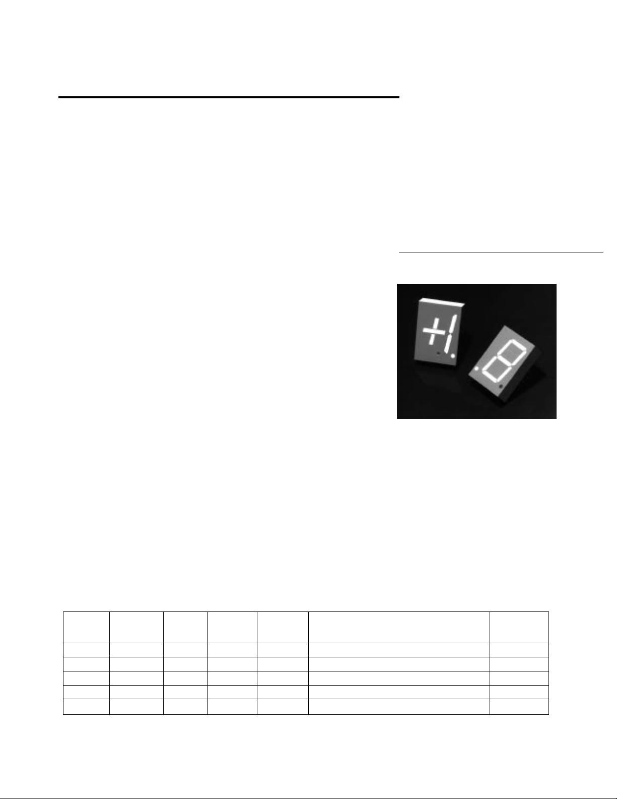
20 mm (0.8 inch)
Seven Segment Displays
H
Technical Data
Features
• Industry Standard Size
• Industry Standard Pinout
15.24 mm (0.6 in.) DIP Leads
on 2.54 mm (0.1 in.) Centers
• Choice of Colors
Red, AlGaAs Red, High
Efficiency Red, Yellow, Green
• Excellent Appearance
Evenly Lighted Segments
Mitered Corners on Segments
Gray Package Gives Optimum
Contrast
± 50° Viewing Angle
• Design Flexibility
Common Anode or Common
Cathode
Left and Right Hand Decimal
Points
± 1. Overflow Character
• Categorized for Luminous
Intensity
Yellow and Green Categorized
for Color
Use of Like Categories Yields a
Uniform Display
• High Light Output
• High Peak Current
• Excellent for Long Digit
String Multiplexing
Intensity and Color
Selection Option
See Intensity and Color
Selected Displays Data Sheet
• Sunlight Viewable AlGaAs
Description
The 20 mm (0.8 inch) LED seven
segment displays are designed
for viewing distances up to 10
metres (33 feet). These devices
use an industry standard size
package and pinout. All devices
are available as either common
anode or common cathode.
HDSP-340X Series
HDSP-390X Series
HDSP-420X Series
HDSP-860X Series
HDSP-N15X Series
These displays are ideal for most
applications. Pin for pin
equivalent displays are also
available in a low current design.
The low current displays are ideal
for portable applications. For
additional information see the
Low Current Seven Segment
Displays data sheet.
Devices
Red AlGaAs
HDSP- HDSP- HDSP- HDSP- HDSP- Description Drawing
3400 N150 3900 4200 8600 Common Anode Left Hand Decimal A
3401 N151 3901 4201 8601 Common Anode Right Hand Decimal B
3403 N153 3903 4203 8603 Common Cathode Right Hand Decimal C
3405 N155 3905 4205 8605 Common Cathode Left Hand Decimal D
3406 N156 3906 4206 8606 Universal ± 1. Overflow
Notes:
1. These displays are recommended for high ambient light operation. Please refer to the HDSP-N10X AlGaAs data sheet for low current
operation.
2. Universal pinout brings the anode and cathode of each segment's LED out to separate pins. See internal diagram E.
3-92
[1]
HER Yellow Green Package
[2]
E
5964-6426E
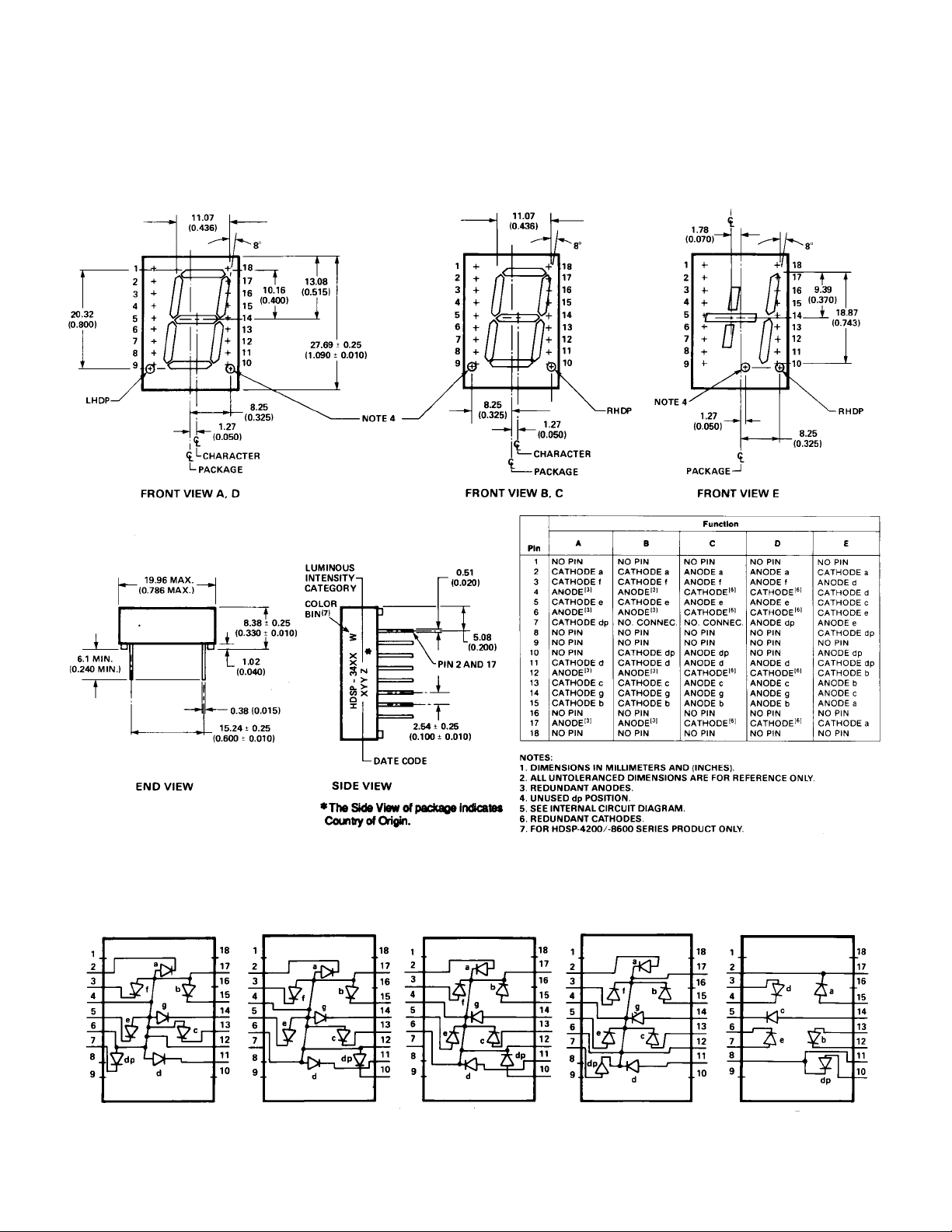
Package Dimensions
Internal Circuit Diagram
A
CB
D
E
3-93
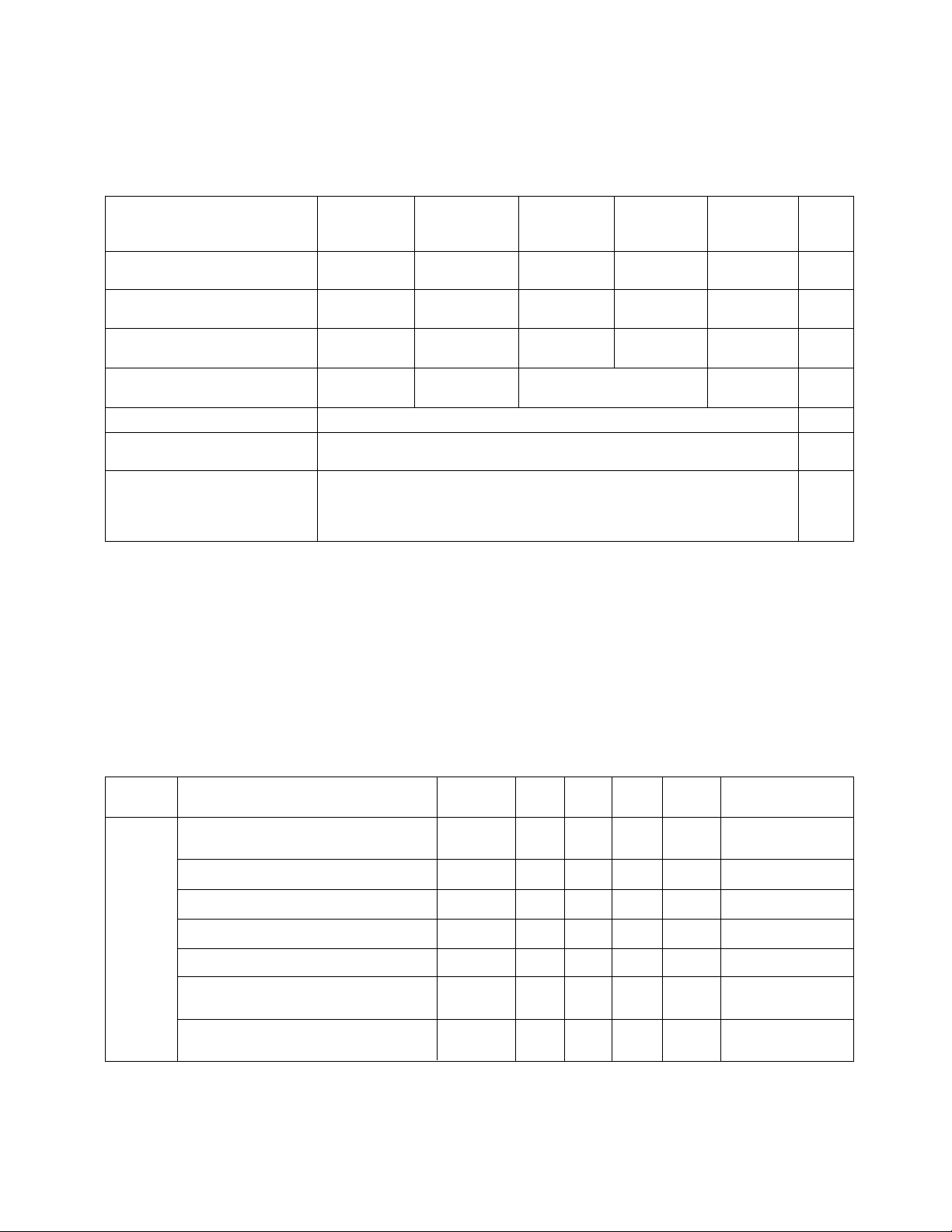
Absolute Maximum Ratings
Red AlGaAs Red HER Yellow Green
Description Series Series Series Series Series Units
Average Power per Segment 115 96 105 105 105 mW
or DP
Peak Forward Current per 200
Segment or DP
DC Forward Current per 50
Segment or DP
Operating Temperature -40 to +100 -20 to +100
Range
Storage Temperature Range -55 to +100 °C
Reverse Voltage per 3.0 V
Segment or DP
Lead Solder Temperature
for 3 Seconds (1.60 mm 260 °C
[0.063 in.] below seating
plane)
Notes:
1. See Figure 1 to establish pulsed conditions.
2. Derate above 45°C at 0.83 mA/°C.
3. See Figure 2 to establish pulsed conditions.
4. Derate above 55°C at 0.8 mA/°C.
5. See Figure 7 to establish pulsed conditions.
HDSP-3400 HDSP-N150 HDSP-3900 HDSP-4200 HDSP-8600
[1]
[2]
160
40
[4]
[3]
[5]
135
[6]
40
[9]
-40 to +100 -40 to +100 °C
6. Derate above 50°C at 0.73 mA/°C.
7. See Figure 8 to establish pulsed conditions.
8. Derate above 50°C at 0.54 mA/°C.
9. For operation below -20°C, contact your local HP
components sales office or an authorized distributor.
135
40
[6]
[5]
90
30
[7]
[8]
mA
mA
Electrical/Optical Characteristics at T
= 25°C
A
Red
Device
Series Parameter Symbol Min. Typ. Max. Units Test Conditions
[3]
[1,2]
[4]
I
V
F
PEAK
λ
d
V
R
J-PIN
500 1200 µcd IF = 20 mA
1.6 2.0 V IF = 20 mA
655 nm
640 nm
3.0 20 V IR = 100 µA
375 °C/W
Luminous Intensity/Segment
(Digit Average)
Forward Voltage/Segment or DP V
HDSP- Peak Wavelength λ
340X
Dominant Wavelength
Reverse Voltage/Segment or DP
Temperature Coefficient of ∆VF/°C -2 mV/°C
/Segment or DP
V
F
Thermal Resistance LED Junction- Rθ
to-Pin
3-94
Loading...