


HP HDSP-K403, HDSP-H403, HDSP-H401, HDSP-H157, HDSP-H153 Datasheet
...14.2 mm (0.56 inch) Seven Segment Displays
Technical Data
Features
•Industry Standard Size
•Industry Standard Pinout
15.24mm (0.6 in.) DIP Leads on 2.54 mm (0.1 in.) Centers
•Choice of Colors
AlGaAs Red, High Efficiency
Red, Yellow, Green, Orange
•Excellent Appearance
Evenly Lighted Segments Mitered Corners on Segments Gray Package Gives Optimum Contrast
±50° Viewing Angle
•Design Flexibility
Common Anode or Common Cathode
Single and Dual Digits Right Hand Decimal Point
±1. Overflow Character
•Categorized for Luminous Intensity
Yellow and Green Categorized for Color
Use of Like Categories Yields a Uniform Display
•High Light Output
•High Peak Current
•Excellent for Long Digit String Multiplexing
•Intensity and Color Selection Option
See Intensity and Color Selected Displays Data Sheet
•Sunlight Viewable AlGaAs
Description
The 14.2 mm (0.56 inch) LED seven segment displays are designed for viewing distances up
Devices
HDSP-K40x Series
HDSP-550x Series
HDSP-552x Series
HDSP-560x Series
HDSP-562x Series
HDSP-570x Series
HDSP-572x Series
HDSP-H15x Series
HDSP-H40x Series
to 7 metres (23 feet). These devices use an industry standard size package and pinout. Both the numeric and ± 1 overflow devices feature a right hand decimal point. All devices are available as either common anode or common cathode.
Orange |
AlGaAs Red |
HER |
Yellow |
Green |
|
Package |
HDSP- |
HDSP-[1] |
HDSP-[1] |
HDSP- |
HDSP- |
Description |
Drawing |
H401 |
H151 |
5501 |
5701 |
5601 |
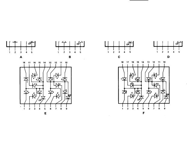
Common Anode Right Hand Decimal |
A |
H403 |
H153 |
5503 |
5703 |
5603 |
Common Cathode Right Hand Decimal |
B |
|
|
|
|
|
|
|
|
H157 |
5507 |
5707 |
5607 |
Common Anode ± 1. Overflow |
C |
|
H158 |
5508 |
5708 |
5608 |
Common Cathode ± 1. Overflow |
D |
K401 |
|
5521 |
5721 |
5621 |
Two Digit Common Anode Right Hand Decimal |
E |
|
|
|
|
|
|
|
K403 |
|
5523 |
5723 |
5623 |
Two Digit Common Cathode Right Hand Decimal |
F |
|
|
|
|
|
|
|
Note:
1.These displays are recommended for high ambient light operation. Please refer to the HDSP-H10X/K12X AlGaAs and HDSP-555X HER data sheet for low current operation.
2
These displays are ideal for most applications. Pin for pin equivalent displays are also available in a low current design. The low current displays are ideal
for portable applications. For additional information see the Low Current Seven Segment Displays data sheet.
Part Numbering System
5082 -X X X X-X X X X X HDSP-X X X X-X X X X X
Mechanical Options[1]
00: No Mechanical Option
Color Bin Options[1,2]
0: No Color Bin Limitation
Maximum Intensity Bin[1,2]
0: No Maximum Intensity Bin Limitation
Minimum Intensity Bin[1,2]
0: No Minimum Intensity Bin Limitation
Device Configuration/Color[1]
1: Common Anode
3: Common Cathode
Device Specific Configuration[1]
Refer to Respective Datasheet
Package[1]
H: 14.2 mm (0.56 inch) Single Digit Seven Segment Display
Notes:
1.For codes not listed in the figure above, please refer to the respective datasheet or contact your nearest Agilent representative for details.
2.Bin options refer to shippable bins for a part number. Color and Intensity Bins are typically restricted to 1 bin per tube (exceptions may apply). Please refer to respective datasheet for specific bin limit information.

3
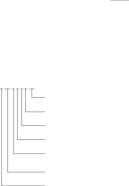
Package Dimensions
|
|
|
|
|
|
|
|
|
|
|
|
|
|
|
|
|
|
|
|
|
|
|
|
|
|
|
|
|
|
|
|
|
|
|
|
|
|
|
|
|
|
|
|
|
|
|
|
|
|
|
|
|
|
FUNCTION |
|
|
|
|
|
PIN |
|
|
|
|
|
|
|
|
|
|
|
A |
B |
C |
D |
|
E |
|
F |
||||
1 |
CATHODE e |
ANODE e |
CATHODE c |
ANODE c |
|
E CATHODE NO. 1 |
|
E ANODE NO. 1 |
|||
2 |
CATHODE d |
ANODE d |
ANODE c, d |
CATHODE c, d |
D CATHODE NO. 1 |
|
D ANODE NO. 1 |
||||
3 |
ANODE[3] |
CATHODE[4] |
CATHODE b |
ANODE b |
|
C CATHODE NO. 1 |
|
C ANODE NO. 1 |
|||
4 |
CATHODE c |
ANODE c |
ANODE a, b, DP |
CATHODE a, b, DP |
DP CATHODE NO. 1 |
|
DP ANODE NO. 1 |
||||
5 |
CATHODE DP |
ANODE DP |
CATHOPDE DP |
ANODE DE |
|
E CATHODE NO. 1 |
|
E ANODE NO. 2 |
|||
6 |
CATHODE b |
ANODE b |
CATHODE a |
ANODE a |
|
D CATHODE NO. 2 |
|
D ANODE NO. 2 |
|||
7 |
CATHODE a |
ANODE a |
ANODE a, b, DP |
CATHODE a, b, DP |
G CATHODE NO. 2 |
|
G ANODE NO. 2 |
||||
8 |
ANODE[3] |
CATHODE[4] |
ANODE c, d |
CATHODE c, d |
C CATHODE NO. 2 |
|
C ANODE NO. 2 |
||||
9 |
CATHODE f |
ANODE f |
CATHODE d |
ANODE d |
|
DP CATHODE NO. 2 |
|
DP ANODE NO. 2 |
|||
10 |
CATHODE g |
ANODE g |
NO PIN |
NO PIN |
|
B CATHODE NO. 2 |
|
B ANODE NO. 2 |
|||
11 |
|
|
|
|
|
|
|
A CATHODE NO. 2 |
|
A ANODE NO. 2 |
|
12 |
|
|
|
|
|
|
|
F CATHODE NO. 2 |
|
F ANODE NO. 2 |
|
13 |
|
|
|
|
|
|
|
DIGIT NO. 2 ANODE |
|
DIGIT NO. 2 CATHODE |
|
14 |
|
|
|
|
|
|
|
DIGIT NO. 1 ANODE |
|
DIGIT NO. 1 CATHODE |
|
15 |
|
|
|
|
|
|
|
B CATHODE NO. 1 |
|
B ANODE NO. 1 |
|
16 |
|
|
|
|
|
|
|
A CATHODE NO. 1 |
|
A ANODE NO. 1 |
|
|
|
|
|
|
|
|
|
|
|
|
|
17 |
|
|
|
|
|
|
|
G CATHODE NO. 1 |
|
G ANODE NO. 1 |
|
18 |
|
|
|
|
|
|
|
F CATHODE NO. 1 |
|
F ANODE NO. 1 |
|
NOTES: |
|
|
|
|
|
|
3. REDUNDANT ANODES. |
|
|
||
1. ALL DIMENSIONS IN MILLIMETRES (INCHES). |
|
4. REDUNDANT CATHODES. |
|
|
|||||||
2. ALL UNTOLERANCED DIMENSIONS ARE FOR REFERENCE ONLY. |
5. FOR HDSP-5600/-5700 SERIES PRODUCT ONLY. |
||||||||||
4
Internal Circuit Diagram
Absolute Maximum Ratings
|
|
HER/Orange |
|
|
|
|
|
|
HDSP-5500 |
|
|
|
|
|
AlGaAs Red |
HDSP-H40x |
|
Yellow |
Green |
|
|
HDSP-H150 |
HDSP-K40x |
HDSP-5700 |
HDSP-5600 |
|
|
Description |
Series |
Series |
|
Series |
Series |
Units |
|
|
|
|
|
|
|
Average Power per Segment or DP |
96 |
105 |
|
80 |
105 |
mW |
|
|
|
|
|
|
|
Peak Forward Current per |
160[1] |
90[3] |
|
60[5] |
90[7] |
mA |
Segment or DP |
|
|
|
|
|
|
|
|
|
|
|
|
|
DC Forward Current per Segment or DP |
40[2] |
30[4] |
|
20[6] |
3018] |
mA |
Operating Temperature Range |
-20 to +100[9] |
|
|
-40 to +100 |
|
°C |
|
|
|
|
|
||
Storage Temperature Range |
|
-55 to +100 |
|
°C |
||
|
|
|
|
|
|
|
Reverse Voltage per Segment or DP |
|
3.0 |
|
|
V |
|
|
|
|
|
|
||
Lead Solder Temperature for 3 Seconds |
|
260 |
|
°C |
||
(1.60 mm [0.063 in.] below seating plane) |
|
|
|
|
|
|
|
|
|
|
|
|
|
Notes:
1.See Figure 2 to establish pulsed conditions.
2.Derate above 46°C at 0.54 mA/°C.
3.See Figure 7 to establish pulsed conditions.
4.Derate above 53°C at 0.45 mA/°C.
5.See Figure 8 to establish pulsed conditions.
6.Derate above 81°C at 0.52 mA/°C.
7.See Figure 9 to establish pulsed conditions.
8.Derate above 39°C at 0.37 mA/°C.
9.For operation below -20°C, contact your local Agilent components sales office or an authorized distributor.
 Loading...