

Page 1

DESIGNJET T120/T520 ePrinter Series
Service Manual
Page 2

© 2012 Hewlett-Packard Development
Company, L.P.
1st edition, August 2012
Legal notices
This document contains proprietary
information that is protected by copyright. All
rights are reserved. No part of this document
may be photocopied, reproduced, or translated
to another language without the prior written
consent of Hewlett-Packard Company.
Page 3

Notices
Warranty
The information contained in this
document is subject to change without
notice.
Hewlett-Packard makes no warranty
of any kind with regard to this
material, including, but not limited to,
the implied warranties of
merchantability and fitness for a
particular purpose.
Hewlett-Packard shall not be liable for
errors contained herein or for incidental
or consequential damages in connection
with the furnishing, performance, or use
of this material.
WARNING
The procedures described in this manual are to
be performed by HP-qualified service
personnel only.
Electrical Shock Hazard
Serious shock hazard leading to death or injury
may result if you do not take the following
precautions:
●
Ensure that the AC power outlet (mains)
has a protective earth (ground) terminal.
●
Disconnect the printer from the power
source prior to performing any
maintenance.
●
Prevent water or any other liquids from
running onto electrical components or
circuits, or through openings in the
enclosure.
Electrostatic Discharge
See the beginning of Chapter 4's Introduction
on page 137 of this manual, for precautions
you should take to prevent damage to the
printer circuits from electrostatic discharge.
WARNING
The Warning symbol calls attention to a
procedure, practice, or the like, which, if
not correctly performed or adhered to,
could result in personal injury. Do not
proceed beyond a Warning symbol until
the indicated conditions are fully
understood and met.
CAUTION
The Caution symbol calls attention to an
operating procedure, practice, or the like,
which, if not correctly performed or
adhered to, could result in damage to or
destruction of part or all of the printer.
Do not proceed beyond a Caution symbol
until the indicated conditions are fully
understood and met.
Customer Assurance
Customer Experience Section
Large Format Printing Division
Hewlett-Packard Española, S.A.
Avenida Graells, 501
08174 Sant Cugat del Vallès
Spain
Safety Symbols
General definitions of safety symbols are given
immediately after the table of contents.
ENWW iii
Page 4

Using this manual
This service manual contains information necessary to test, maintain, and service the following:
HP Designjet T120 Basic Printer 24 inch CQ891A
HP Designjet T520 Pro Printer 24 inch CQ890A
HP Designjet T520 Pro Printer 36 inch CQ893A
For information about using these printers, see the user's guide.
Readership
The procedures described in this service manual are to be performed by HP Certified service personnel only.
Part numbers
Part numbers for printer service parts are located in Parts and diagrams on page 119.
ENWW v
Page 5

Table of contents
1 Printer fundamentals .................................................................................................................................... 1
Overview ................................................................................................................................................................ 1
Using the front panel ............................................................................................................................................. 1
Start-up sequence ................................................................................................................................................. 3
Subsystems ............................................................................................................................................................ 5
2 Troubleshooting .......................................................................................................................................... 33
Printer troubleshooting flowchart ...................................................................................................................... 34
Basic printer troubleshooting ............................................................................................................................. 35
System error codes .............................................................................................................................................. 38
Paper troubleshooting ........................................................................................................................................ 57
Communication troubleshooting ........................................................................................................................ 62
Ink-supplies troubleshooting .............................................................................................................................. 66
Print-quality troubleshooting ............................................................................................................................. 78
Update the firmware ........................................................................................................................................... 91
3 Support menus ............................................................................................................................................ 95
Entering the support menus ............................................................................................................................... 96
Support menu ...................................................................................................................................................... 98
Extended Support menu ................................................................................................................................... 117
4 Parts and diagrams .................................................................................................................................... 119
Introduction ....................................................................................................................................................... 119
Printer support .................................................................................................................................................. 120
Covers ................................................................................................................................................................ 121
Roll covers ......................................................................................................................................................... 122
Right-hand assemblies ..................................................................................................................................... 123
Left-hand assemblies ........................................................................................................................................ 125
Carriage assembly ............................................................................................................................................. 127
Paper path (front) .............................................................................................................................................. 129
Paper path (rear) ............................................................................................................................................... 130
Roll supports ..................................................................................................................................................... 131
Sensor Kit ........................................................................................................................................................... 132
Miscellaneous parts ........................................................................................................................................... 133
ENWW vii
Page 6

5 Removal and installation ........................................................................................................................... 135
Introduction ....................................................................................................................................................... 137
Customer Self Repair parts ............................................................................................................................... 139
Videos available ................................................................................................................................................. 140
Recommended checks after replacing parts .................................................................................................... 140
Top Cover ........................................................................................................................................................... 141
Front Cover ........................................................................................................................................................ 144
Right Cover ........................................................................................................................................................ 147
Ink Cartridge Cover ............................................................................................................................................ 150
Left Cover .......................................................................................................................................................... 152
Roll Cover ........................................................................................................................................................... 154
Back Cover ......................................................................................................................................................... 157
Front Panel ........................................................................................................................................................ 159
Front Panel Cable .............................................................................................................................................. 165
Central Cover ..................................................................................................................................................... 166
Upper-Roll Paper Guide ..................................................................................................................................... 171
Left Roll Support ............................................................................................................................................... 174
Right Roll Support ............................................................................................................................................. 179
Top Cover Sensor ............................................................................................................................................... 182
Top Cover Sensor Cable ..................................................................................................................................... 185
Encoder Strip ..................................................................................................................................................... 187
Ink Cartridge Cover PCA Assembly .................................................................................................................... 192
Power Supply ..................................................................................................................................................... 196
Main PCA ............................................................................................................................................................ 198
Paper Motor ....................................................................................................................................................... 204
Encoder PCA and Index ...................................................................................................................................... 206
Encoder Disk ...................................................................................................................................................... 210
Trailing Cable ..................................................................................................................................................... 213
Service Station ................................................................................................................................................... 220
Prime Pump ....................................................................................................................................................... 226
Carriage and Belt ............................................................................................................................................... 229
Carriage Belt ...................................................................................................................................................... 235
Right Gear Train Module .................................................................................................................................... 237
Starwheel Assembly .......................................................................................................................................... 239
Output Shaft ...................................................................................................................................................... 241
Output Tray ........................................................................................................................................................ 249
Multi-Sheet Tray Assembly ............................................................................................................................... 252
Multi-Sheet Tray Assembly Extensions ............................................................................................................ 253
Output Platen .................................................................................................................................................... 255
Carriage Motor ................................................................................................................................................... 260
Cutter Assembly ................................................................................................................................................ 264
Cutter Guide ....................................................................................................................................................... 271
Out-Of-Paper Sensor ......................................................................................................................................... 273
Out-Of-Paper Sensor Cable ............................................................................................................................... 276
viii ENWW
Page 7

Output Tray Sensor Assembly ........................................................................................................................... 278
Output Tray Extender Sensor Cable .................................................................................................................. 281
Carriage Line Sensor .......................................................................................................................................... 284
Bundle Board ..................................................................................................................................................... 288
Bundle Board FFC cable ..................................................................................................................................... 290
Pinchwheels ....................................................................................................................................................... 295
Left Spittoon ...................................................................................................................................................... 301
6 Preventive maintenance ............................................................................................................................ 305
Preventive maintenance ................................................................................................................................... 306
Preventive maintenance kits ............................................................................................................................ 312
7 Appendices ................................................................................................................................................ 315
Important links .................................................................................................................................................. 316
Front-panel home screen and menu map ........................................................................................................ 317
Support menu tree ............................................................................................................................................ 327
Extended Support menu tree ............................................................................................................................ 328
How to check whether your computer is connected to your network ............................................................. 329
Wireless troubleshooting report error cases .................................................................................................... 332
CSR fliers ............................................................................................................................................................ 341
ENWW ix
Page 8

1 Printer fundamentals
●
Overview
●
Using the front panel
●
Start-up sequence
●
Subsystems
Overview
Feature HP Designjet T120 HP Designjet T520 More information
Paper source Roll and multi-sheet tray See the user's guide
Hardware differences Stand as an accessory, no roll
cover
Connectivity Wi-Fi, Fast Ethernet LAN, USB Important! LAN and Wi-Fi are
Web Services Automatic firmware upgrade
HP Designjet ePrint & Share
Printing by email
Speed 70 s per page on A1/D 35 s per page on A1/D
Resolution Up to 1200 × 1200 dpi Up to 1200 × 2400 dpi
Memory and languages 256 MB, HP-PCL3 (processing
in printer)
Supplies HP 711 29 ml Cyan, Magenta, Yellow
HP 711 38 ml and 80 ml Black
One on-axis printhead for all colors
Stand in box, roll cover
1 GB, HP-GL/2 (processing in
computer)
not compatible
The printer needs to be
Internet-connected: Web
Services do not work with a
USB connection. For some
configurations, the latest
firmware release is needed.
Manual firmware upgrade is
available in both printers via
HP Designjet Utility (Windows)
or HP Utility (Mac OS). The
same firmware file is used for
T120 and T520.
Ink cartridges and printhead
can be replaced by the
customer.
Using the front panel
The front panel is a touch-sensitive screen with a graphical user interface; it is located on the front left of the
printer. It gives you complete control of your printer: from the front panel, you can print, view information
ENWW Overview 1
Page 9

about the printer, change printer settings, perform calibrations and tests, and so on. The front panel also
displays alerts (warning and error messages) when needed.
The front panel has a large central area to display dynamic information and icons. On the left and right sides
you can see up to six fixed icons at different times. Normally they are not all displayed at the same time.
To the right of the front panel is the Power key, with which you can turn the printer on or off. The key is
illuminated when the printer is on. It flashes when the printer is in transition between on and off.
Left and right fixed icons
●
shows the status of the wireless connection: if the blue light is shining, the wireless connection is active.
●
Press to return to the home screen.
●
Press to view help about the current screen.
●
Press to go to the previous item.
●
Press to go to the next item.
●
Press to go back to the previous screen.
●
Press to cancel the current process.
Home screen dynamic icons
The following items are displayed only on the home screen.
●
At the top left of the home screen is a message telling you which paper source is active.
●
Press to view Web Services status and display your printer’s email address.
●
Press to view connectivity status information and to perform network configuration. If a network cable
is connected, is displayed instead.
NOTE: It is not possible to use wireless and wired network connections simultaneously.
●
Press to view ink information.
●
Press to change printer settings.
●
Press to load, unload, and change options for roll paper.
●
Press to change options for the multi-sheet tray, or to activate it.
●
Press to load, unload, and change options for single sheets.
●
Press to access HP Designjet ePrint & Share.
NOTE: The active paper source is indicated by a slightly larger icon, with a white tick in a green circle: .
2 Chapter 1 Printer fundamentals ENWW
Page 10
If the printer is left idle for some time, it goes into sleep mode and switches off the front-panel display. To
change the time that elapses before sleep mode, press , then Printer preferences > Sleep. You can set a time
between 5 and 240 minutes.
The printer wakes from sleep mode and switches on the front-panel display whenever there is some external
interaction with it.
The following table shows an overview of the two types of support menu available, for more details see
Entering the support menus on page 96.
NOTE: The icons mentioned in this table will not be visible in the front panel: you must press the front panel
in the places where they normally appear, as shown in the front panel illustration at the start of this section.
Label Description
Support menu: This can be used by customers under the
guidance of phone call agents assisting remotely. Using this
menu, customers can perform troubleshooting tasks and access
printer information.
Extended Support menu: Service engineers only From the Home screen, press the following icons one after the
Start-up sequence
There are three states between power-on and the Home screen:
1. Electronics initialization
2. Firmware initialization
3. Mechanical initialization
State 1: Electronics initialization
1. The front panel moves from flashing white light to turning dark.
2. The printer reads the firmware.
From the Home screen, press the following icons one after the
other: , ,, .
If there is a system error, you may not be able to reach the home
screen. In this case, press the Power button and hold it down for
15 seconds.
other: , , , .
NOTE: At this stage, if something is broken, it will not be possible to enter the Support menu. To diagnose
what is happening, go to the front panel blank troubleshooting. (and add here the link). Subsequently, you
can enter the Support menu to troubleshoot if necessary.
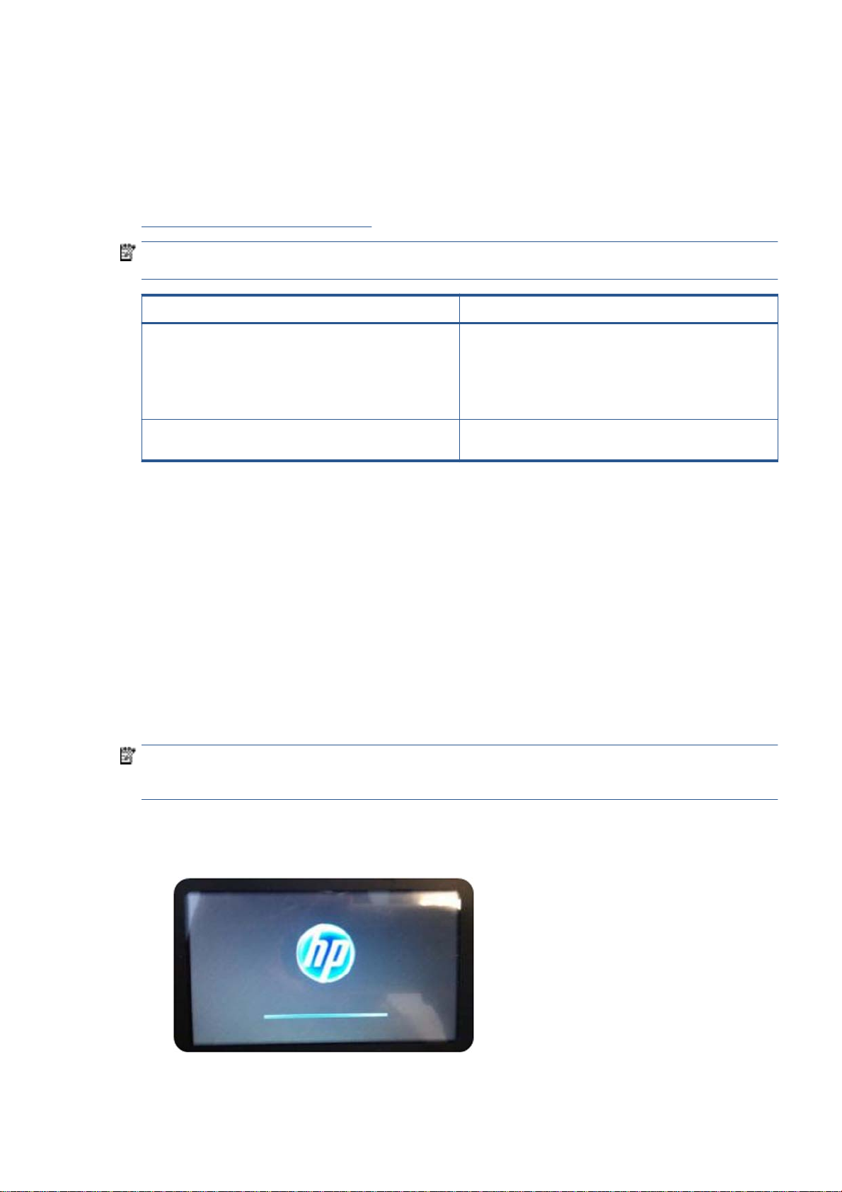
State 2: Firmware initialization
1. The HP logo appears with a static bar.
2. Bundle board and ASICs are initialized.
ENWW Start-up sequence 3
Page 11
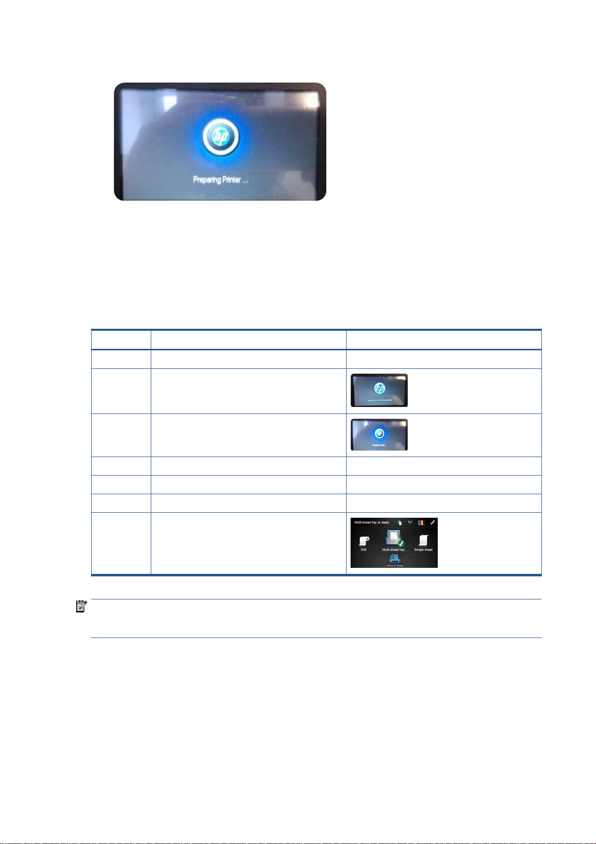
3. The HP logo changes.
State 3: Mechanical initialization
1. A basic check of servos
2. A check that the Scan Axis and Paper Axis are unobstructed by scraps of paper or other items
3. Paper and print system initialization
Initialization flow summary
Time (sec) Printer state Visual and acoustic information
0 Power on Using the Power button
10 Electronics initialization
27 Mechanical initialization
1. Basic check of servos Sound of the printer's motors
2. Scan Axis, Paper Axis check Carriage movement
3. Paper and print system initialization Paper movement
45 Ready state
NOTE: Initialization lasts around 45 s if there was a clean power-off (using the front panel Power button). If
there was a dirty power-off, the printer will require more time to inititialize (to ensure that the printhead is in
a good state).
4 Chapter 1 Printer fundamentals ENWW
Page 12
Subsystems
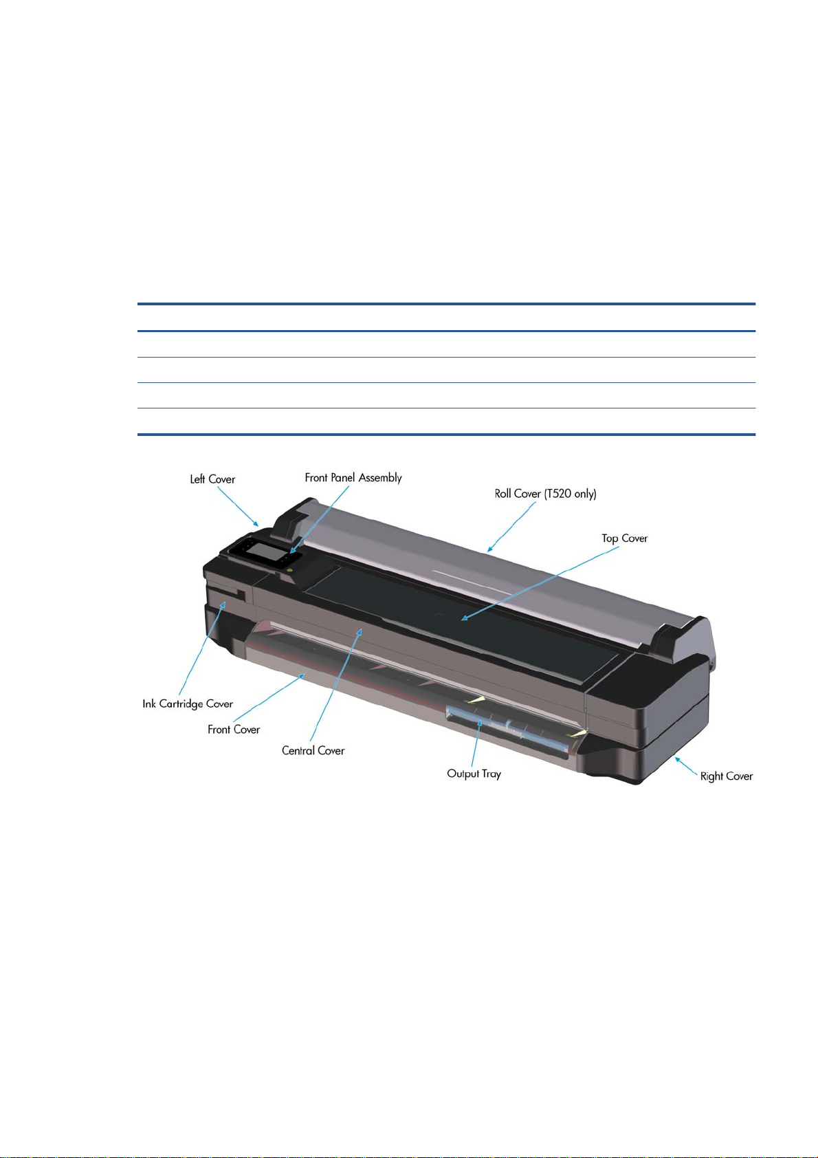
Covers
Functionality
These parts cover the printing mechanism and act as protection from potential knocks or dust. They also
prevent the customer from coming into contact with unsafe parts during the operation of the printer. Finally,
the covers complement the style and aesthetics of the printer.
The T120 and T520 printers have covers of different colors, and a different configuration of the roll cover, as
seen in the following table:
HP Designjet T120 HP Designjet T520
Roll Cover Not Present Transparent
Top Cover Opaque Black Transparent
Output Platen Black-Blackberry Black-Olive
Output Tray Black-Olive Black-Olive
Components
Other than the cosmetic aspects of the covers, there are several sensors related to the subsystem covers.
The sensors are designed to detect the status of the cover, open or closed.
ENWW Subsystems 5
Page 13

●
The Ink Cartridge Cover Sensor senses whether the Ink Cartridge Cover is open or closed. Opening the
Ink Cartridge Cover starts ink cartridge replacement automatically. The sensor is hosted in the printer
chassis.
●
The Central Cover hosts the Top Cover Sensor to sense whether the Top Cover is open or closed.
IMPORTANT: Be careful to avoid damaging the sensor while removing the Central Cover. See Central
Cover on page 166.
●
The Output Tray Sensor senses whether the Output Tray is open or closed. To avoid paper jams while
printing on roll paper, the tray should be closed.
IMPORTANT: Damage to the covers can cause the sensors to malfunction.
Removal and installation
In order to proceed with the removal and installation of the covers its important to bear in mind their
cosmetic aspects, some surfaces of the covers have a glossy finish, which requires maximum attention as
they are very delicate and susceptible to scratches and finger marks. It is recommended that you use gloves
for any service operation involving the covers.
Due to the layout of the covers, it is important to bear in mind that some parts require removal before you
can remove a specific cover.
●
Right Cover requires Front Cover removal.
●
Left Cover requires Front and Ink Cartridge Cover removal.
●
Roll Cover requires Right and Left Cover removal.
●
Top Cover requires Front Panel assembly removal.
●
Central Cover requires Right Cover and Left Cover removal.
Related tests
Sensor tests for the Top Cover, Ink Cartridge Cover, and Output Tray operation. See Diagnostics menu
on page 100.
Electronics
Other than the sensor boards, there are no electronics related to this subsystem.
Printhead health systems: Service Station, Primer system, and Left Spittoon
Functionality
The service station is responsible for printhead maintenance. It takes action to clean ink residues and service
ink nozzles, and prevents ink from drying in critical zones by capping the printhead once printing has
finished.
The Primer system provides the necessary air pressure to the printhead to perform initialization. This system
also provides pressure to the necessary printhead service operations (by boosting air which pushes ink out
through the printhead nozzles, cleaning residues of dried ink and other particles).
The Left spittoon is a small container located to the left of the print-zone area, this is the area used by the
printhead to “spit” a small amount of ink at the end/beginning of the printing swath in order to ensure
correct nozzle heath for left-to-right printing.
6 Chapter 1 Printer fundamentals ENWW
Page 14
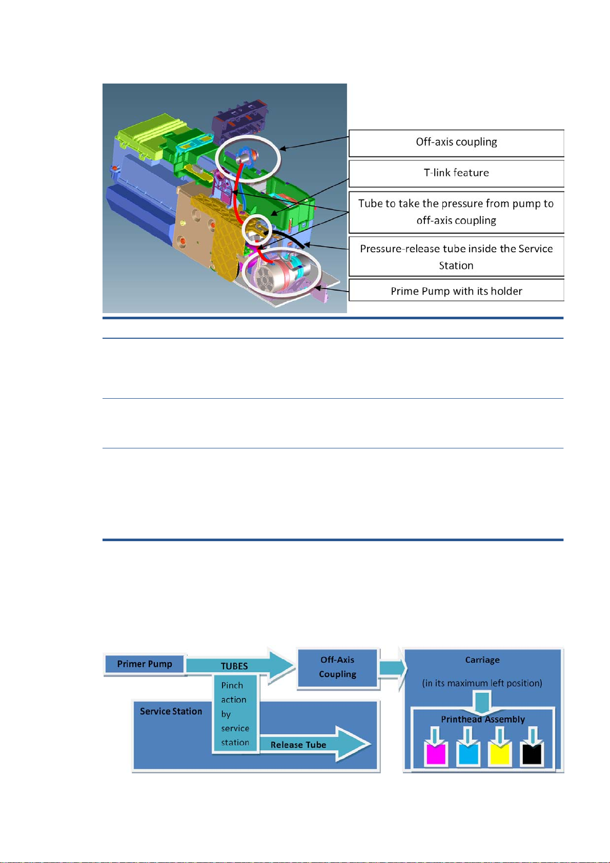
Components
Item Function
Off-axis coupling assembly This is a rubber spring link located on the side plate of the scan
axis (area where the Carriage moves). It links the primer system
with the Carriage when the Carriage is located in its maximum left
position. This system ensures the pressure from the primer
reaches the printhead for nozzle servicing.
Prime Pump This is an air pump which provides the necessary pressure for
Primer Tubes The tubes take the air from the Prime Pump to the off-axis
Notes and considerations
Any leakage in the primer system will generate poor or no priming, this will affect nozzle heath (or even
cause the printhead startup to fail). Bear in mind that the system is not just for the Prime Pump and tubes,
the prime pressure is transmitted via the off-axis coupling to the Carriage and from there to the printhead
assembly and from there to the cartridges.
printhead servicing and nozzle repair. The Prime Pump is
suspended on a rubber holder to minimize the noise that the
Prime Pump makes while in operation.
coupling. There is a T link feature connected to a tube that goes
inside the service station; the purpose of this tube is to release
the air pressure from the system. The tube is pinched by the
shuttle of the service station when reaching a certain position;
this action closes the circuit and allows the system to be
pressurized. With the movement of the service station the tube is
released, allowing the pressure from the system to escape.
ENWW Subsystems 7
Page 15
NOTE: There is no pressure sensor in the system. The Prime Pump operates at a certain time to reach a
specific pressure level, the system is depressurized by releasing the pinching of the release tube in the
Service Station (by moving the service station).
NOTE: It is important to ensure the Carriage reaches the maximum left position; if not, the off-axis coupling
will not connect the Prime Pump with the Carriage. Also, the coupling is made of a rubbery material,
degradation of the material will affect Primer performance due to air leaks.
Electronics
The control driver of the Prime Pump is located on the remote controller board located on the right-hand side
of the printer. There is no encoder for the Prime Pump. This pump is managed only by a DC motor activated
for a certain period of time to create the required priming pressure.
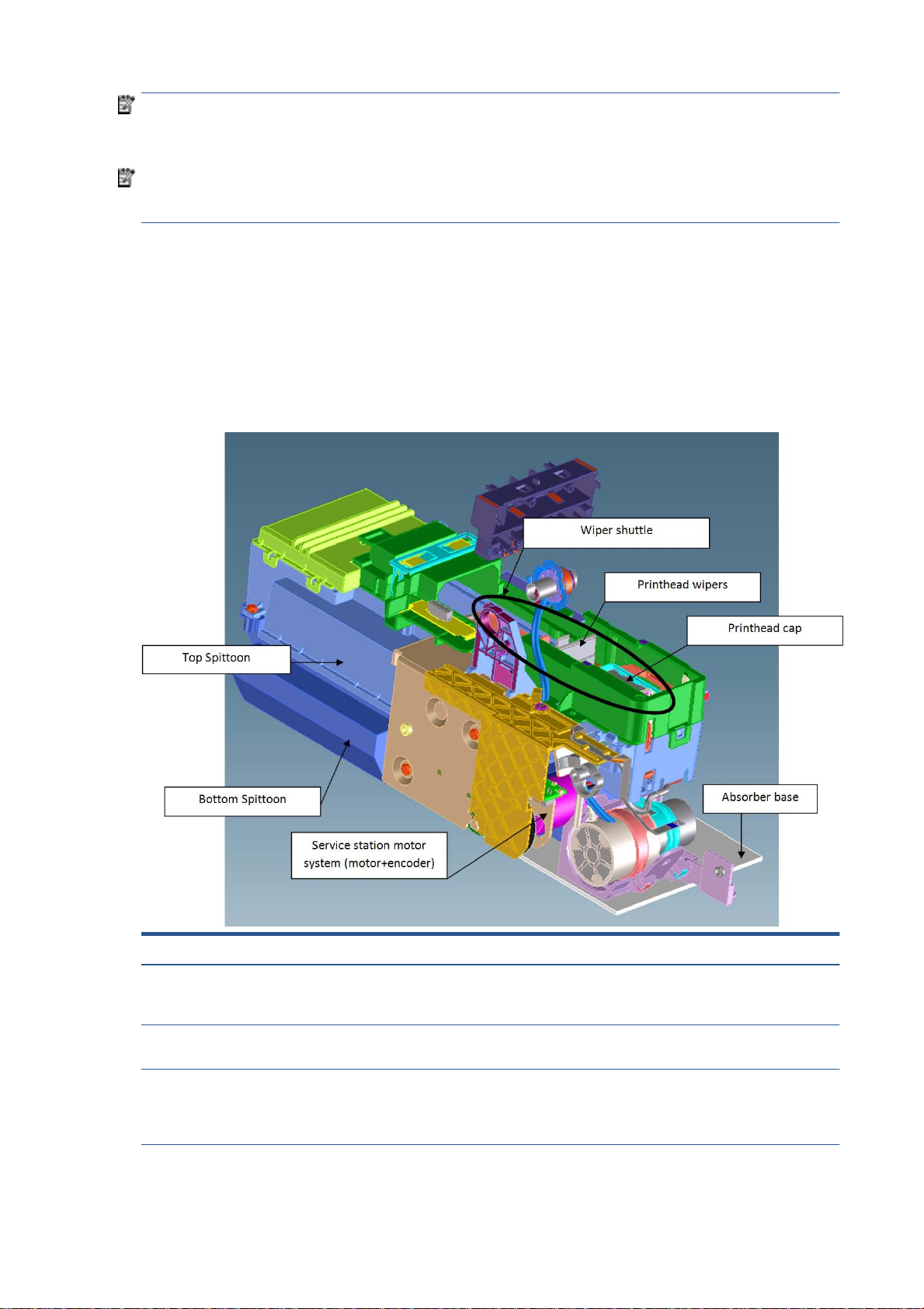
Service Station system
Functionality
Item Function
Printhead Wipers These are rubber paddles that are passed through the nozzle
plate of the printhead with the Service Station movement. They
clean the excess ink from the nozzle plate with a rubbing action.
Printhead Cap This caps and protects the nozzles from drying when they are not
printing.
Service Station Motor system This moves the shuttle with the wiper and the cap so that these
two items can perform their functions. The system is composed
of a DC motor and an encoder disk with an encoder sensor to read
the motor position.
8 Chapter 1 Printer fundamentals ENWW
Page 16

Item Function
Bottom Spittoon This part acts as an ink reservoir when spitting and nozzle health
operations are performed. It contains diapers that prevent the ink
becoming liquid.
Top Spittoon This seals the reservoir and completes the main body of the
service station.
Absorber Base This is made of foam and is located under the service station on
top of the printer structure. It works as an additional diaper in
case ink spills out of the Service Station.
Wiper Shuttle This mobile part is propelled by the motor that contains the Wiper
and Cap. Depending on the position, spitting, wiping, capping, or
priming can take place:
Spitting: The printhead “spits” a little ink into the spittoon to get
the nozzles conditioned and ready for the next swath of printing.
Wiping: A physical action to pass the rubber wipers through the
printhead nozzles.
Capping: Parking the printhead to maintain nozzle heath during
printer inactivity, with a surrounding seal.
Priming: Squirts ink through the nozzles to clean and unblock
them.
Notes and considerations
The service station is offered as a complete service part for full replacement. The failures from this
subsystem are usually related to the mobile parts: motor or encoder failures that prevent the shuttle from
reaching the positions for capping or uncapping.
With the life primer system, tube pinching can present an issue (although it is designed to function for the life
of the printer).
When the Service Station is replaced, it is mandatory to reset the Preventive Maintenance Kit for the Service
Station, this will trigger a simple calibration that is done with the Service Station on the next printer startup.
The calibration measures the length of the Service Station (shuttle front bump to shuttle rear bump), which
ensures a correct capping position.
Electronics
All the controlled movements for the Service Station are done from the remote-controlled board located on
the right-hand side of the printer. Issues with the Service Station can also be related to this control board.
Paper path and Cutter
Functionality
The paper path
This comprises all the elements of the printer in contact with the paper, designed to hold, move, and manage
it in a controlled manner in order to print.
Paper can be loaded using a roll, which is mounted on the rear spindle, or single sheets loaded from the
Multi-Sheet Tray, or single sheets loaded singly.
The paper passes from its source (Roll, Single Tray, or Multi-Sheet Tray) until it touches the Out-Of-Paper
Sensor, when the printer detects the presence of the paper and proceeds to load it.
ENWW Subsystems 9
Page 17
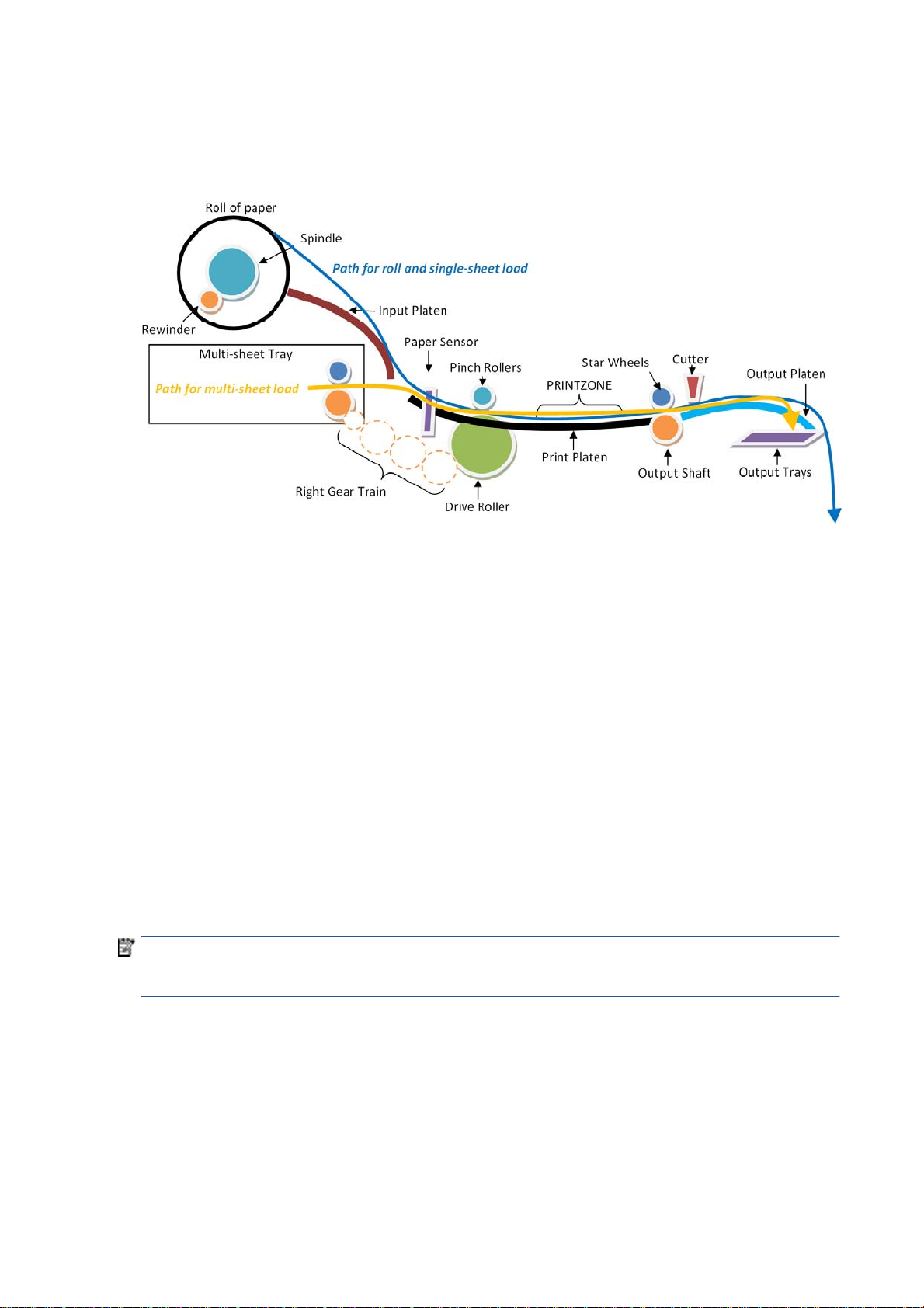
To perform the paper feed, the printer catches the paper in between the Drive Roller and the Pinch Rollers
(Pinch Rollers are spring-loaded pushing the paper down on top of the Drive Roller), then the paper is pushed
forwards on top of the Print Platen in the print zone, which is where the printing operation is performed. The
paper advance is provided by a motor that moves the Drive Roller. The exact position of the Drive Roller and
hence the paper is controlled by an Encoder Disk located on the roller axis.
The printed paper then passes between the Output Shaft and the Starwheels (which keep the paper tension
as flat as possible for printing) to exit on the Output Platen, where it is held in case of cut sheet or is cut to
fall on the output basket in the case of roll paper.
The Output Shaft is designed to over-advance the Drive Roller movement slightly, and hence create the
necessary paper tension to keep the paper as flat as possible. The Starwheels are spring-loaded and are
designed to create force on top of the paper, this is done so as to leave the paper unmarked and at the same
time allow the Output Shaft force to be appropriately transmitted.
In the Roll configuration, the rewinder module generates back force while printing to facilitate paper control.
A key electrical element of the paper path is the Paper Sensor (also known as the Out-Of-Paper Sensor or
OOPS). This sensor is located at the beginning of the Print Platen; it detects paper insertion for roll load and
single-sheet load.
Electronics
In the paper-path driving system, the only electrically active element is the Drive Roller. The Drive Roller is
impelled by the drive roller motor and it contains an Encoder Disk on the axis to determine its position. The
Encoder Disk is read by two sensors. One, the “encoder sensor”, designed to read the encoder, counts the
Encoder Disk (the Encoder Disk outer marks) and another one, the “encoder index sensor”, determines the
start position (the 0 position) of the Drive Roller by reading the inner thicker lines of the Encoder Disk.
NOTE: Every time the printer starts up, it searches for the 0 position of the Drive Roller. If this search fails
(which means that the index sensor is faulty), the printer will give a system error and will be unable to
initialize.
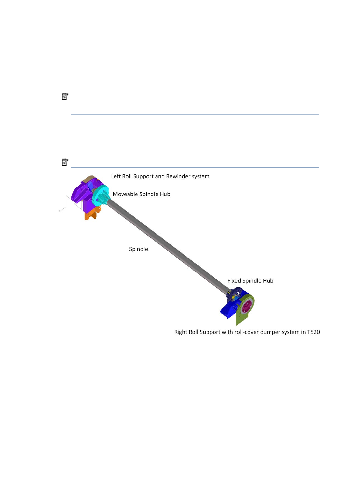
The roll paper input system
Functionality
This system keeps the roll in place and ensures controlled rotation.
It contains the rewinder, which rewinds the paper for paper ejection, and provides an opposite tension to the
paper advance for better paper control.
10 Chapter 1 Printer fundamentals ENWW
Page 18
●
The Left Support encloses the Rewinder Motor and Encoder, containing a set of gears that transmit the
Rewinder motion to the spindle. There is a V-shaped spring to load and fix the spindle in position.
●
The Right Support holds the spindle in position to rotate over passive rollers.
In the T520, the right support also contains the dampers for the roll cover opening movement control
(the internal dampers perform a braking action preventing sudden movement during the opening
operation).
NOTE: The right support for the T120 models does not contain dampers. The T120 and T520 have two
different assemblies from the factory, nevertheless both can be replaced by the damper option of T520
(identical from the external point of view), and there is only one service part available.
●
The spindle is designed to hold the paper rolls, and receive the motion from the rewinder gear in the
Left Support. It consists of a central bar and two hubs; the right hub is fixed to determine the right-side
loading position of the paper, and the moveable left hub adjusts to the width of the paper.
●
The Roll Cover (T520 only) shields the roll from dust.
NOTE: The Roll Cover is a passive part, with no sensor: the printer does not know its status.
Electronics
The Rewinder Motor and Encoder system are directly controlled by the Main PCA.
The paper output system
Functionality
The system ensures that the printed paper follows a controlled path and acquires a certain shape in order to
be delivered properly to the user. It also has a cosmetic function.
The system includes a set of three telescopic trays, which are extended to collect the cut-sheet paper printed
from the Multi-Sheet Tray.
ENWW Subsystems 11
Page 19
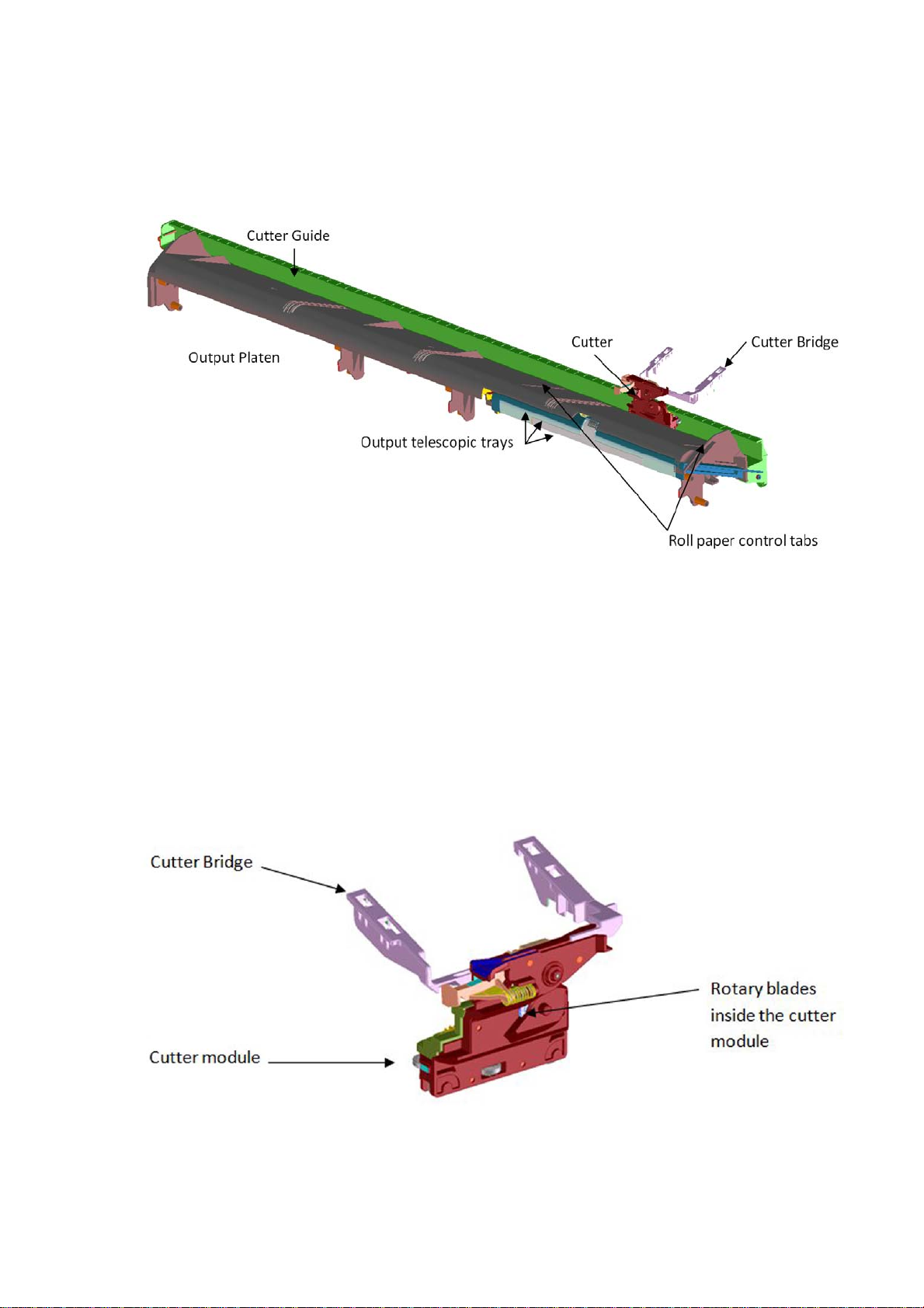
There are two roll-paper control tabs that are deployed automatically when the telescopic trays of the
Output Tray are in the closed position. This is a purely mechanical action as the tabs are pushed up by the
output trays when closed. The purpose of those tabs is to control the shape of the roll paper when coming
out of the paper path.
The Front Cover is located underneath the Output Platen.
Electronics
The only electronic component related to the Output Platen is the Output Tray Sensor located underneath
the output trays. The sensor is activated when the three output trays are fully closed. The sensor cable is
routed via the front of the machine and is directly connected to the main PCA.
The Cutter system
The Cutter cuts the paper after the print has completed.
It comprises 1) a cutter module that cuts the paper with two rotary blades, 2) a Cutter Bridge attached to the
Carriage that catches and releases the Cutter to perform the cutting operation and then to leave it in capping
position, 3) a Cutter Guide that holds the movement of the Cutter along the printer width.
In order to operate the Cutter, it needs to be in the parked position. If not, the Cutter will not be engaged by
the Cutter Bridge and the printer will not perform the cutting action.
12 Chapter 1 Printer fundamentals ENWW
Page 20
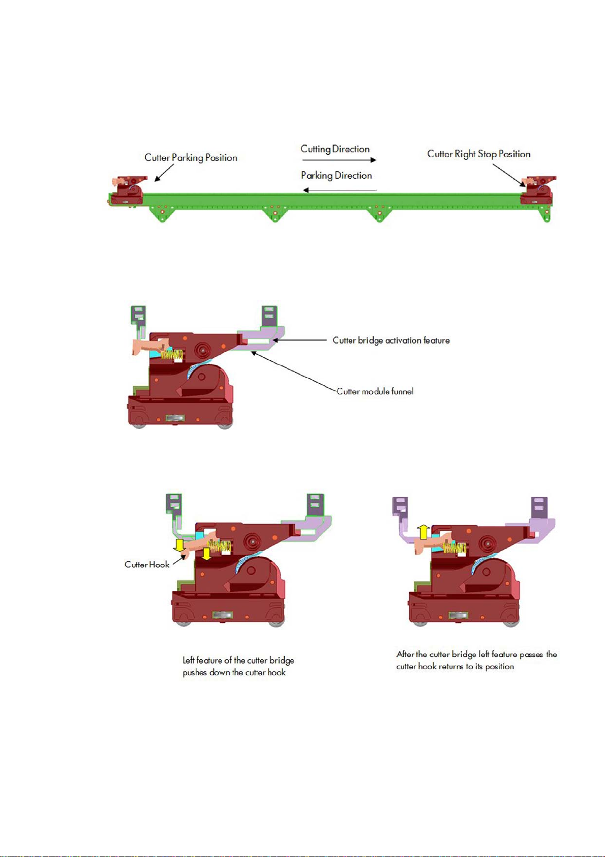
Whenever the printer initializes, it performs a parking movement with the Carriage to ensure that the Cutter
is left in the appropriate position.
The printer does not have any feedback about the cutter engagement action. Hence, if for any reason the
engagement is not performed correctly, the printer will continue operating as if the engagement has
occurred.
How activation works
1. Pre-activation phase: The Cutter Engagement Feature of the Bridge gets into the funnel of the Cutter
Module grooving the Cutter to ensure the correct position for activation.
2. Hook catching: The cutter bridge continues moving to the left pushing down the cutter hook (in orange),
after the left side of the cutter bridge passes the Carriage stops and the cutter hook returns to its
position due to its spring motion.
ENWW Subsystems 13
Page 21
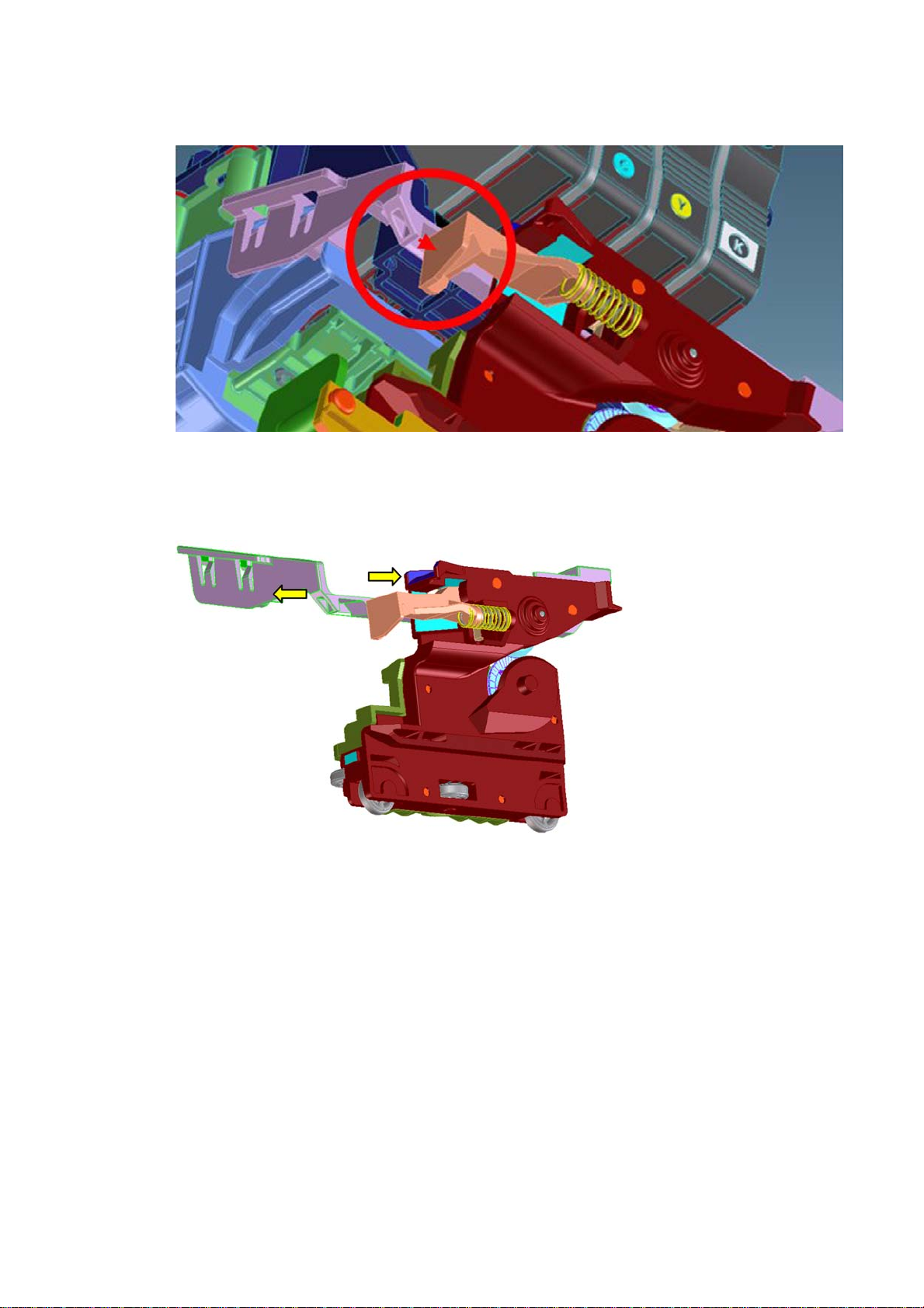
3. Cutter action: The left feature of the cutter bridge pushes the cutter to the left, performing the cutting
operation.
How deactivation works
1. Disengagement: Hook Bridge changes direction moving now from right to the left, so that Cutter Hook
slides out of the Cutter Catch Feature.
14 Chapter 1 Printer fundamentals ENWW
Page 22
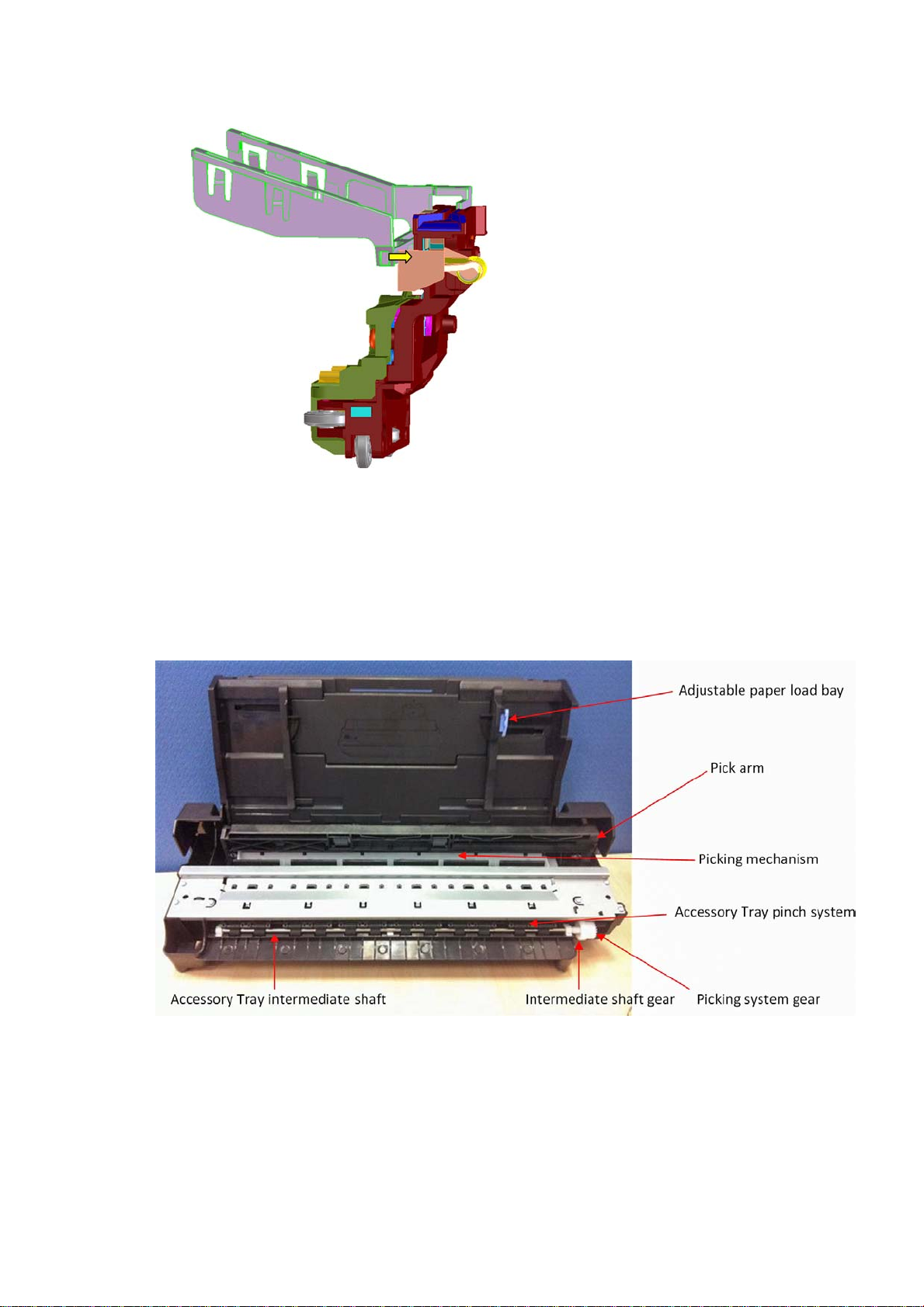
2. Move-away action: the Cutter Hook deactivates from the bridge by passing in front of it.
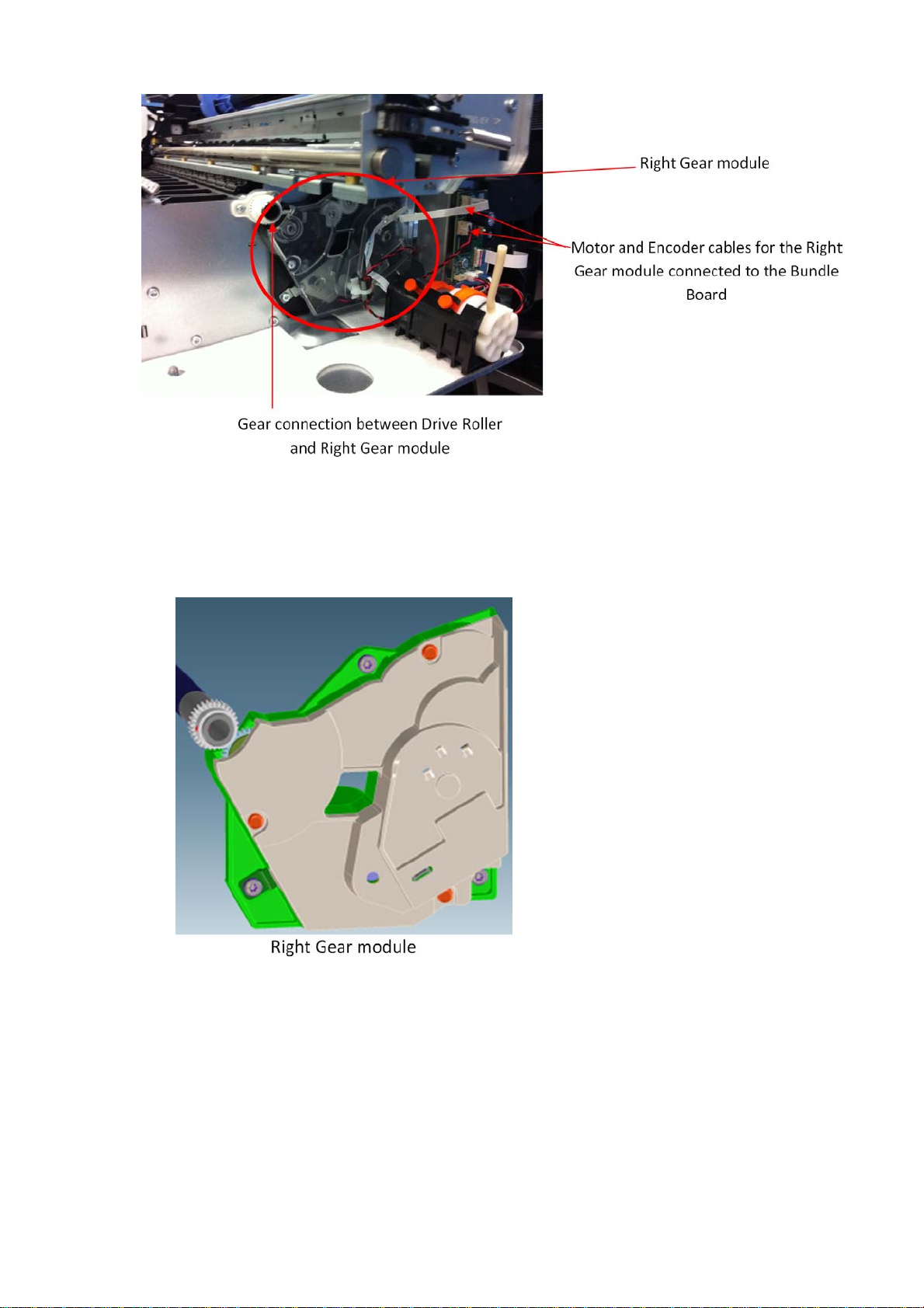
Accessory tray and right gear module
Functionality
The accessory tray holds and loads the cut-sheet paper for the printer. The accessory tray itself is a
completely mechanical system with no electronics or motors. All the motion drives for both picking and paper
drive are or created or transmitted by the Right Gear module located on the right-hand side of the printer,
behind the Service Station.
The Right Gear module has two main functions. It contains the motor encoder and gear drive system for the
picking mechanism, and it contains the gear train system to transmit the movement from the drive roller to
the accessory tray.
ENWW Subsystems 15
Page 23
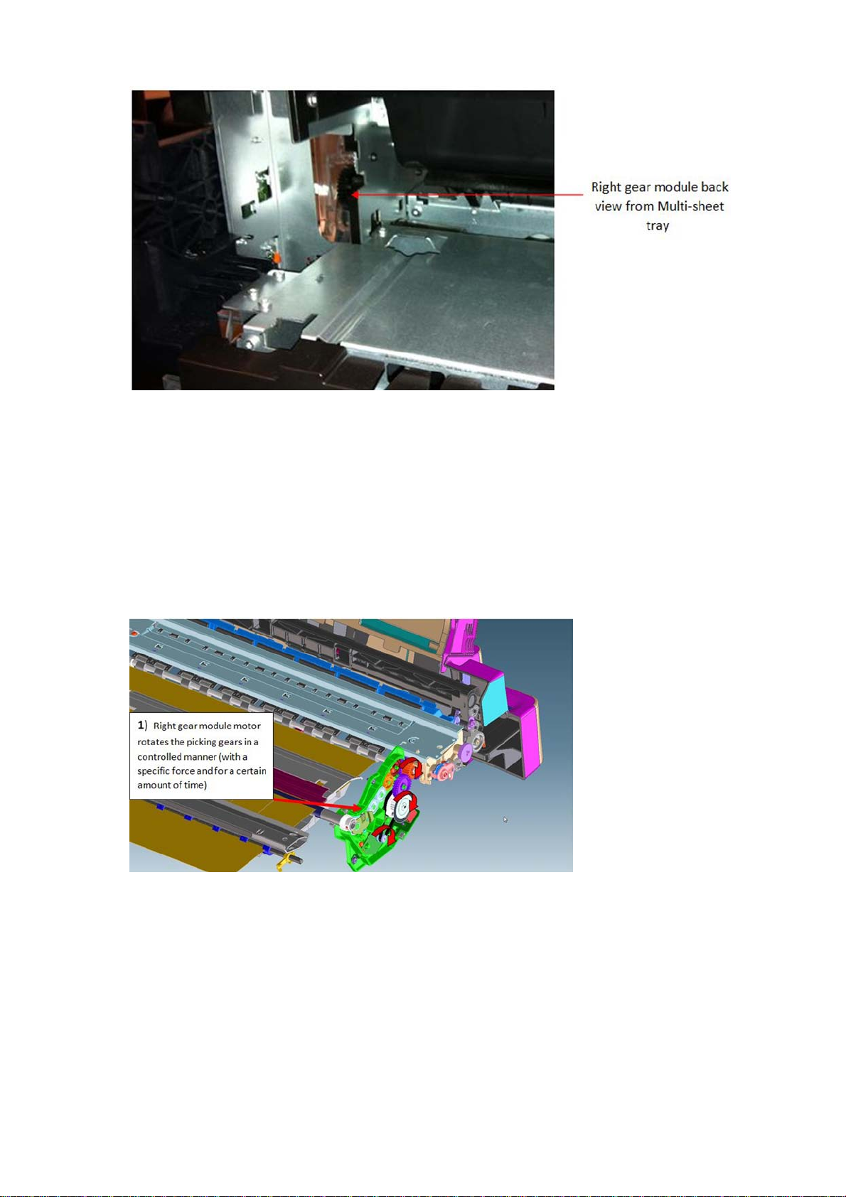
Right Gear module functionality
The Right Gear module has two different functions associated with the Multi-Sheet Tray.
1. The paper drive from the Multi-Sheet Tray into the platen area (until the cut sheet reaches the drive
roller area).
16 Chapter 1 Printer fundamentals ENWW
Page 24
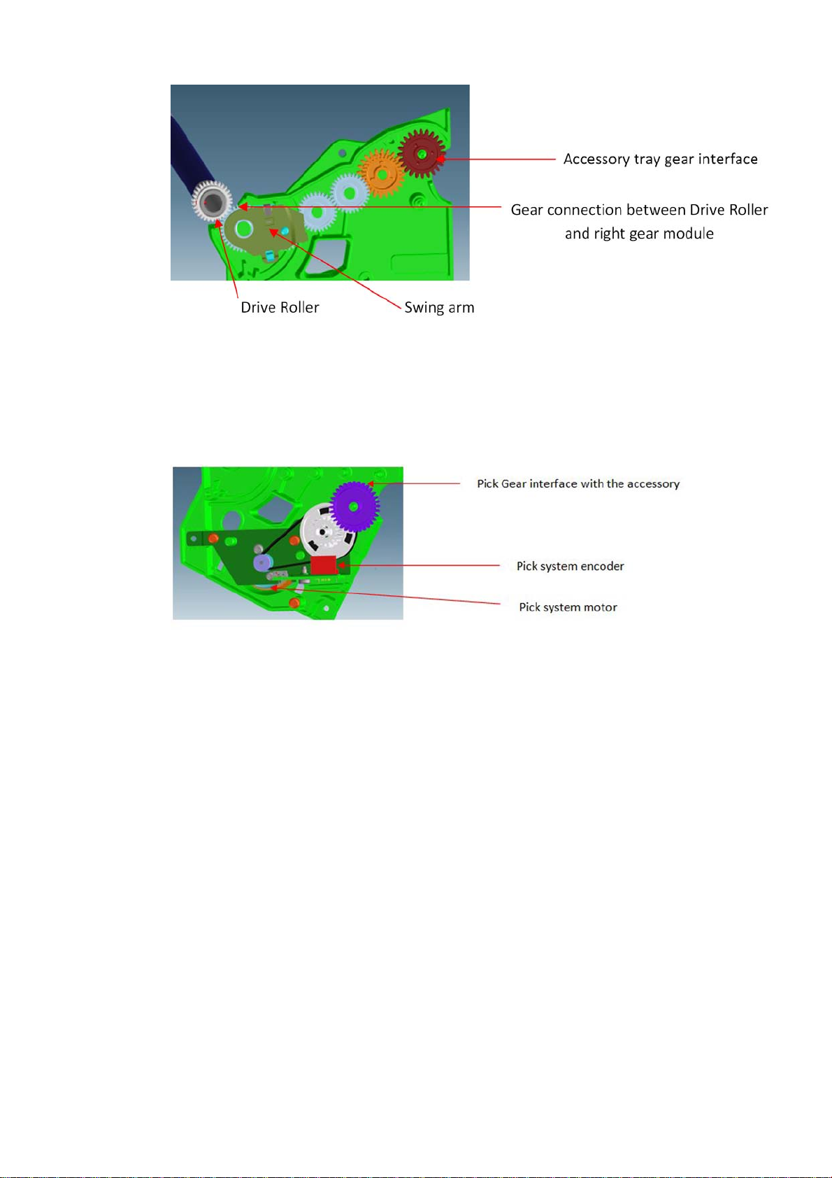
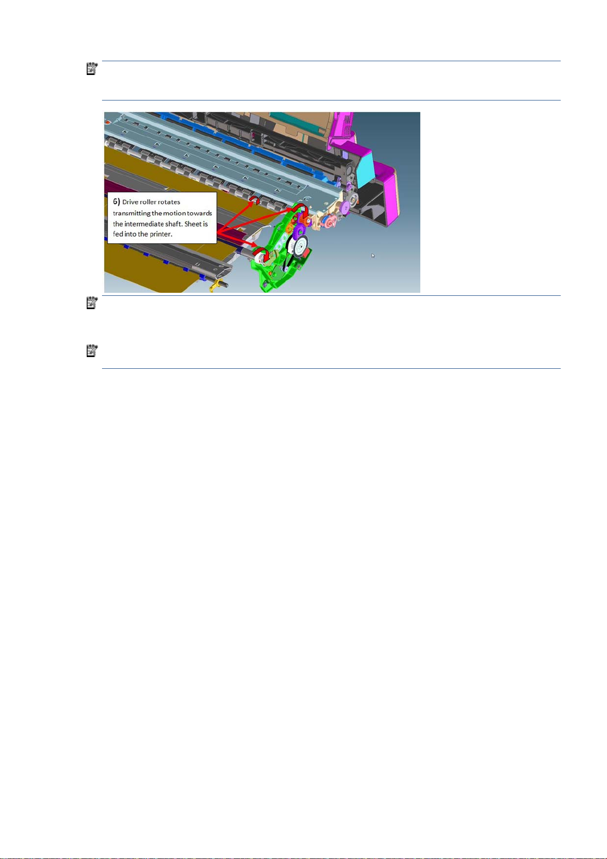
The intermediate shaft in the Multi-Sheet Tray is driven by the drive roller through a gear train inside
the Right Gear module. The intermediate shaft meshes with the Multi-Sheet Tray gear interface (red
gear in the picture) at the end of the train. A swing arm engages the gear train when the Drive Roller is
driven backwards (as shown in the picture), driving the intermediate shaft forwards. When the Drive
Roller is driven forwards, the swing arm disengages from the gear train and the intermediate shaft is
not driven. This action is to prevent reverse paper movement to be transmitted to the Multi-Sheet Tray.
2. Picking functionality drive system
The Multi-Sheet Tray pick drive assembly is mounted in the right side gear module. The assembly
contains a DC motor and pinion, belt, cluster pulley, and gear. An encoder (not shown, but it is located in
front of the white gear shown in the picture) is read by the encoder sensor (in red in the picture) to
servo-control the pick drive.
Right Gear and Multi-Sheet Tray interface
The two gears from the Right Gear module interface with the Multi-Sheet Tray by location once the MultiSheet Tray is locked in position; both gears can be considered fully engaged.
ENWW Subsystems 17
Page 25
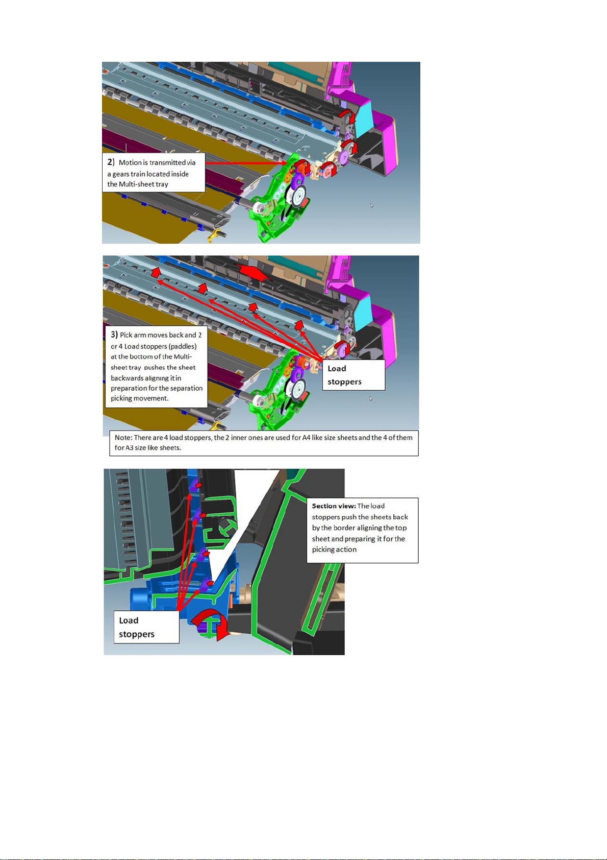
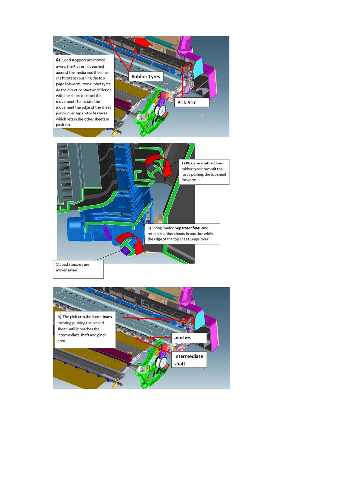
Multi-Sheet Tray functionality
The function of the Multi-Sheet Tray is to pick and feed the cut-sheet paper until the paper is grabbed by the
drive roller (drive roller and pinch system).
The actions performed for those operations are (1) sheet pick and (2) sheet input.
1. Sheet pick
This movement is transmitted through a lateral gear chain in the Multi-Sheet Tray towards the swing arm,
which is pushed towards the paper, and the picking mechanism located at the bottom of the Multi-Sheet
Tray, which separates the top sheet from the stack of pages.
18 Chapter 1 Printer fundamentals ENWW
Page 26
ENWW Subsystems 19
Page 27
2. Sheet input
Once the paper is in the intermediate shaft area, the drive roller is rotated, impelling the intermediate shaft
through the right gear module, pushing the sheet towards the inside of the printer, so that it will be grabbed
by the drive roller and main printer pinch system, proceeding with the standard paper drive motion (as with
roll paper).
20 Chapter 1 Printer fundamentals ENWW
Page 28
NOTE: The printer considers the load successful if, after the picking and sheet input procedures, the sheet
is detected by the printer's Paper Sensor. Hence, a correct function of the Paper Sensor is required also for
the accessory tray loading action.
NOTE: It is possible to reproduce the picking and loading motions by extracting the Multi-Sheet Tray and
rotating the gears with the hand, to validate module performance and troubleshoot any possible mechanical
issues.
NOTE: Different elements of the Multi-Sheet Tray are not serviceable, the whole module requires
replacement in case of failure.
Electronics
Both the encoder and motor-drive system are managed by the Bundle PCA located on the right-hand side of
the printer.
Scan Axis system: Carriage and Carriage impelling
This system moves the Carriage from left to right and right to left of the printer on top of the paper in a
controlled manner to perform printing, cutting, paper detection, and any other Carriage movements for
servicing and final capping process.
The system comprises the Carriage sliding on the scan axis rod, on which rotates and whose position is
determined by a cam mounted on the Carriage, which slides touching the bottom surface of the anti-rotation
rail.
There are two trailing cables mounted one on top of the other, which connect the Carriage with the main
electronics control board. A scan-axis encoder strip is needed for the Carriage to determine its position, and a
Carriage Motor which impels the Carriage via a belt.
The trailing cable is held in position by a plastic holder, which clips onto the scan axis structure. A springloaded loop ensures follow-up action of the cables with the Carriage movement. Two plastic cable sliders are
also placed to ensure minimum contact of the trailing cables with the scan axis structure. The plastic sliders
are greased to prevent ink spray (aerosol) deposits from accumulating on them, generating a sticky surface
which could retain the cables and then be damaged by Carriage movement.
ENWW Subsystems 21
Page 29
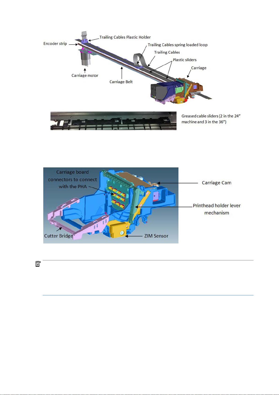
The Encoder Strip Sensor is located inside the Carriage, once the Carriage is assembled the Encoder Strip
crosses the Carriage, passing by the detection area of the sensor inside the Carriage.
The main function of the Carriage is to hold the printhead in position, to enable cartridge insertion, and to
move the printhead in a controlled manner in order to print.
The Carriage holds all the necessary interface electronics for the main board to interact with the printhead
via the trailing cables. A set of spring-loaded connectors are the main interface Carriage-printhead.
NOTE: It is very important that the contacts are clean, free of dust/ink to ensure a correct connection
between printhead and Carriage, as high-speed data are transmitted through this connection, and dust could
cause sporadic system errors. This is particularly important when replacing the printhead, as the removal of
the old printhead (extraction with a rotary movement) can cause the nozzle plate to touch those contacts and
create contamination that could cause problems with the new printhead. However, manual cleaning of the
contacts is not recommended.
The Carriage also has additional functionality:
1. Transmits the pressure from the Prime Pump via off-axis coupling to each of the four cartridges
●
Off-axis coupling connects with the Carriage via the side connection bay:
22 Chapter 1 Printer fundamentals ENWW
Page 30
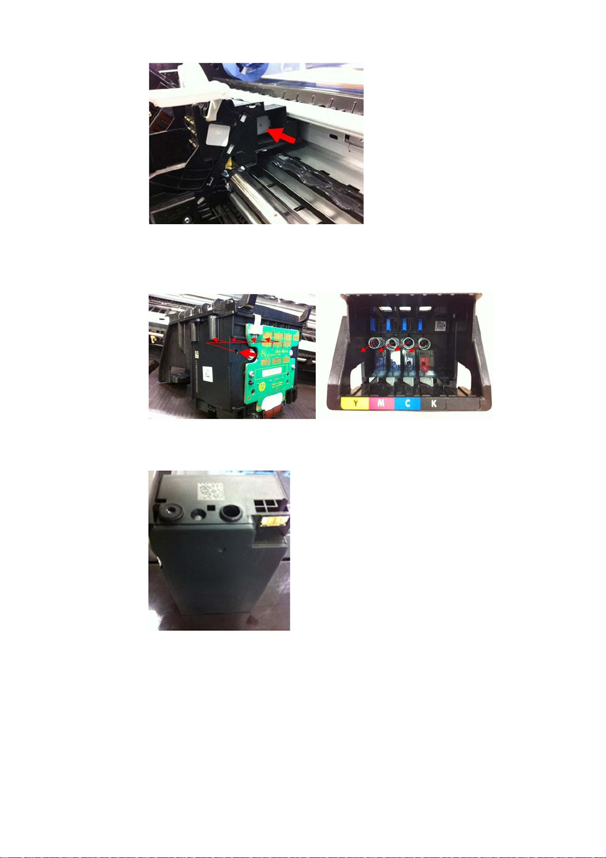
●
An internal passage of the Carriage transmits the air pressure towards the printhead.
●
The rear hole of the printhead receives the air pressure which is distributed towards the four air
ports inside the printhead.
●
Each of the air ports transmits the air pressure to the cartridges, and the air pushes the inner
chambers, expelling the ink during the priming operation.
2. Holds the cutter bridge
The cutter bridge impels the Cutter for cutter operations (see additional information in the cutter
section).
ENWW Subsystems 23
Page 31

3. Holds the Carriage Line Sensor
The Carriage Line Sensor (also known as the ZIM Sensor) is located on the right of the printer and is used
to detect the edges of the paper to determine the paper dimensions and start position. This sensor is
also the tool used to detect the position of printed lines to perform calibrations (Paper Advance
calibration and printhead alignment).
The Line Sensor is a reflective tool that generates a beam of LED light, whose reflection is detected by a
luminance sensor. The signal from this sensor is used to determine the position of lines or paper edge
according to the position of the Carriage.
NOTE: Both LED emitter and receiver sensor inside the line sensor are protected by a transparent
plastic cover. If this cover becomes dirty, the signal to detect edges or lines will be affected, which could
cause intermittent issues during the paper load.
It can also detect printed lines from short signals when the sensor crosses the lines:
24 Chapter 1 Printer fundamentals ENWW
Page 32

Carriage CAM and Auto PPS adjustment
At the back of the Carriage there is a sliding cam that determines the PRS (Print to platen Rib Space) of the
Carriage. In manufacturing, the anti-rotation rail (area in which the PRS cam slides) is adjusted to calibrate
the nozzle plate position of the printhead, at around 1.6 mm all along the scan axis width. This calibration is
not service-adjustable and should remain constant throughout the printer's life.
As there are different paper thicknesses, the printer is able to rotate this sliding cam automatically to three
different positions, changing the PRS distance to accommodate it to the appropriate printing distance.
This rotation is performed by taking the Carriage to a feature on the left-hand side of the scan axis, different
side movements of the Carriage at different speeds allow this feature to grab and rotate the cam accordingly.
The Cam has three different areas for three different PRS adjustments.
Auto-PRS feature located on the left-hand side of the scan axis.
Back part of the Carriage with auto-PPS cam, after being activated in position 1.
Carriage impelling system
ENWW Subsystems 25
Page 33

Carriage encoder system
The encoder strip tension is also fixed by a tensioning spring. However, there is a mechanism to hold it in
position after the spring places the strip at one specific tension. This is to prevent the spring from continually
applying force over the encoder strip; which, over time and temperature changes, could make it creep.
NOTE: When assembling the encoder strip, ensure that it is placed in the right orientation using the smiling
symbol located on the sides of the encoder strip.
NOTE: Due to the proximity of the encoder strip to the greased sliding rod, it is easy to dirty the strip with
grease when performing any repair operation in the area. Please clean any grease from the encoder strip if
necessary. A dry cloth can be used for this purpose, to prevent any deformation or strain on the encoder strip
while performing the cleaning.
26 Chapter 1 Printer fundamentals ENWW
Page 34

Printer electronics, power supply, and cables
The printer contains several electronics boards and electrical and electronic components in different
locations.
●
There are two main active boards (Main PCA and Bundle PCA).
●
One WiFi Module, which provides the WiFi functionality to the printer.
●
One interface board (Carriage PCA), which provides and converts the appropriate signals for the Carriage
(printhead interface and line sensor signaling) .
●
Three on/off sensor PCAs (Top Cover Sensor, Out Of Paper Sensor or OOPS, Output Tray Sensor), which
indicate the open/closed status of the different elements.
●
One active on/off sensor (the Ink Cartridge Cover sensor). Apart from indicating the open/closed status
of the ink cartridge cover, it includes the backup memory for all factory calibration values.
●
One encoder sensor and a feed index sensor (other than the encoder sensors located inside the
Rewinder, the Right Gear Module, and the Service Station).
●
One Power Button PCA. Located in the front panel, it is used to power the printer on and off.
●
One Power Supply (PSU), which converts the AC power line (110–240 V AC) into the DC power needed by
the printer (32 V and 12 V).
The standard wiring used in the printer is Flat Flexible Cables (FFCs), to interconnect all boards (including
sensors and encoders) and distributed cables for power signals to the motors.
NOTE: It is important to bear in mind that FFCs are relatively delicate, so please ensure cable connectors
are not touched or dirtied during manipulation for assembly and disassembly operations.
NOTE: Ensure that you are properly grounded for any electronics or wiring manipulation.
ENWW Subsystems 27
Page 35

The Main PCA
The Main PCA is located on the left-hand side of the printer. This board is the “brain” of the printer: where all
the processing and printer management occurs; control of the overall machine (digital and mechatronics)
with the battery for the Real-Time Clock.
There are two versions depending on memory size: Basic (256 MB) for the T120 and Pro (1 GB) for the T520.
The Main PCA also contains other elements with the following functions:
●
●
●
●
Battery: To maintain the internal clock up and running. The internal clock is used to remember the
actual date, used for cartridge life counting and warranty accounting.
WiFi module: Attached to the top of the board with some plastic locators, provides WiFi functionality to
the printer.
USB dongle: Where the firmware of the printer is stored.
NOTE: This dongle does not operate as a standard USB drive. It is a customized device designed to
interact with the main electronics, and all the data are appropriately encrypted.
Buzzer: To provide acoustic signals to the user.
28 Chapter 1 Printer fundamentals ENWW
Page 36

The Bundle Board
The Bundle Board is located on the right-hand side of the printer, this board includes a driver ASIC to control
and manage the motor, encoder, and sensors located on the right-hand side of the printer.
IMPORTANT: The pick encoder and Service Station cables are not poka-yoke cables: it is possible to
connect them incorrectly, in which case a system error will result.
Electrical system
The following diagram describes the connections between components and electronic boards, the voltage,
and the type of data line.
ENWW Subsystems 29
Page 37

●
The printer contains a total of 11 printed circuit boards (PCA).
●
The OOP sensor, Top Cover, and Feed Index are exactly the same board.
●
The WiFi PCA, although included in the Main PCA Service Kit, is a different board used in other products.
Part Brief technical function
Main PCA (PRO/BASIC) Has two versions depending on memory size: Basic (256 Mb) and
Pro (1Gb)
Bundle Board Mechatronics driver for the right part of the machine motors and
encoder
Front panel and power button Tactile color visual screen with buzzer for machine power up and
down, control, and user interface
Ink Cartridge cover Sensor Ink Cartridge Cover opening state control
Carriage PCA => Part of Carriage assembly Carriage control and feed for printhead spitting
OOPS Paper presence detection
Output Tray sensor Front tray state control (open or closed)
Top Cover sensor Top Cover state control (open or closed)
Feed index Encoder to detect the paper placement (absolute)
Feed encoder Encoder to control the exact advance of the paper (relative)
Wifi PCA Radio module (including antenna) to give wireless capabilities
(802.11 b/g)
30 Chapter 1 Printer fundamentals ENWW
Page 38

Locations of the PCAs
ENWW Subsystems 31
Page 39

2 Troubleshooting
●
Printer troubleshooting flowchart
●
Basic printer troubleshooting
●
System error codes
●
Paper troubleshooting
●
Communication troubleshooting
●
Ink-supplies troubleshooting
●
Print-quality troubleshooting
●
Update the firmware
ENWW 33
Page 40

Printer troubleshooting flowchart
Use the following as a guide to troubleshooting issues with the printer:
34 Chapter 2 Troubleshooting ENWW
Page 41

Basic printer troubleshooting
The printer does not print
If all is in order (paper loaded, all ink components installed, and no file errors), there are still reasons why a
file you have sent from your computer may not start printing when expected:
1. You may have an electrical power problem. If there is no activity at all from the printer, and the front
panel does not respond, check that the power cord is connected correctly and that there is power
available at the socket.
2. You may be experiencing unusual electromagnetic phenomena, such as strong electromagnetic fields or
severe electrical disturbances, which can cause the printer to behave strangely or even stop working. In
this case, turn off the printer using the power key on the front panel and unplug the power cord, wait
until the electromagnetic environment has returned to normal, then turn it on again. If you still
experience problems, please contact your customer service representative.
3. You may not have installed in your computer the correct driver for your printer.
4. If you are printing on a sheet, you must specify Printer Autoselect or Single-Sheet or Multi-Sheet Tray
as the paper source in your printer driver.
The Front Panel is blank (the printer does not start)
If the printer does not start (the front panel is blank), try the following:
Remote troubleshooting
1. Ask the customer to unplug and plug in the power cord. The customer should check when the power
cord is plugged in that the front panel is illuminated (white) for a few moments, after which the printer
should start the initialization process.
2. If the front panel is still blank (does not show a flashing white screen), and the printer does not start up,
then ask the customer to hold down the Power key for a few seconds and ask to check whether the
Power LED button turns orange while the key is held down.
3. If the customer does not see the orange light, no power is reaching the printer; ask to check that the
power cord is correctly plugged in. If the problem persists, there is a problem with the power supply.
Arrange a service engineer visit to replace the Power Supply, see Power Supply on page 196.
●
Main Power Supply – CQ890-67025
4. If the customer sees the orange light, ask to unplug and plug in the power cord and to listen and wait for
around 30 seconds for the printer to make a beeping sound.
5. Three beeps mean that the Front Panel has failed or the Front Panel cable is disconnected or damaged.
Arrange a service engineer visit to check the cable and replace the Front Panel if needed, see Front
Panel on page 159.
●
Front Panel – CQ890-67026
6. One long beep means an electronic problem. Arrange for a service engineer visit to replace the Main
PCA. To check that the Main PCA is broken you can ask the customer to open the Ink Cartridge Cover and
check whether there is a green light (heartbeat LED) flashing in the left bottom part .
ENWW Basic printer troubleshooting 35
Page 42

If there is no light or it is not flashing the Main PCA should be replaced.
●
Main PCA Basic: CQ891-67003
●
Main PCA Pro: CQ890-67023
7. If the printer initializes and the Carriage moves but the front panel is still blank, the Front Panel should
be replaced, see Front Panel on page 159.
●
Front Panel – CQ890-67026
See also the troubleshooting flowchart for this issue on the next page.
36 Chapter 2 Troubleshooting ENWW
Page 43

ENWW Basic printer troubleshooting 37
Page 44

System error codes
Understanding system error codes
Error messages are generally used to report internal system errors. The following pages contain a list of
system error codes and their respective descriptions and recommended corrective actions. Try only one
recommended action at a time, in the order that they appear, and check whether the error code has
disappeared.
Advisory error messages
Advisory error messages communicate that some action must be performed, such as adding paper or
clearing a paper jam. Take the appropriate action to continue printing.
Problem type Message (with customer
troubleshooting)
Printhead missing/Not detected/
Incompatible
Ink Cartridge problem The following cartridges appear to be
Ink Sensor failure (sensor inside the PHA) Ink Sensor failure This error is continuable (the customer can
Paper mismatch Paper detected does not match paper size
Paper jam There is a paper jam (or misfeed). Clear the
The printhead appears to be missing, not
detected, or incorrectly installed.
missing or damaged [list of affected
supplies]
or type selected.
jam and press Resume on the printer.
There is a paper jam (or misfeed) in the
scan path. Clear the jam or re-insert the
document and restart the task.
Details for call agent
See Printhead troubleshooting
on page 75.
Replace the listed supplies. See Replace an
ink cartridge on page 66.
press OK and keep working). However if
the message appears continuously after
restarting the printer or while sending new
jobs, it is very likely that the Carriage PCA
is not working properly. Arrange a service
engineer visit to change the Carrriage.
If the paper size is correct, check that the
line sensor is OK by running the Line
Sensor diagnostic from the Support Menu.
This occurs when trying to load the paper.
There is no need to turn off the printer.
Run the Carriage Servo and Paper Servo
diagnostics from the Support Menu.
This occurs when the paper is already
loaded. There is no need to turn off the
printer. Run the Carriage Servo diagnostic
from the Support Menu.
The printer is out of paper Load more paper and press Resume on the
front of the printer.
Incompatible Cartridge(s) The cartridge is not intended for use in this
printer.
Ink Cartridge Cover open Replace ink cartridges and close the ink
cartridge cover.
Top Cover open Please close Top Cover Perform the Top Cover sensor diagnostic
Load paper The printer is not able to complete the
load because it cannot detect the paper
Out of memory Out of memory Job sent to the printer too complex, see
Run OOP sensor diagnostic from the
Support Menu.
Ask the customer to install the correct ink
cartridge.
Perform the ink cartridge cover sensor
diagnostic from the Support Menu.
from the Support Menu.
Perform the OOP sensor diagnostic from
the Support Menu.
the user's guide for more details.
38 Chapter 2 Troubleshooting ENWW
Page 45

Problem type Message (with customer
troubleshooting)
Details for call agent
Improper shutdown To avoid damage, use the On button to
shut down. Do not use a power strip or
wall switch to shut down.
Printer or ink system error There is a problem with the printer or ink
system. Turn printer off, then on. If the
problem persists, contact HP.
Follow the front-panel message.
Ask the customer to retrieve the Error
History, see 1.5 Error history on page 98.
Ask the customer which of these 2 errors
are logged:
●
26:10
●
27:10
Follow the applicable error
troubleshooting.
ENWW System error codes 39
Page 46

Severe error codes
Severe error messages inform you of a device failure. Some of these messages can be cleared by pressing
the Power button to turn off the printer, and then pressing it again to turn the printer back on. If a severe
error persists, service is required.
System error Component/System
01.1:10 Main PCA (MPCA) failure
01.1:19 Incorrect Main PCA installed
01.3:10 Bundle Board failure
02:10 Carriage Board Failure
03.1:10 Battery of Real-Time Clock ran down
08:10 Front Panel does not respond
21:10 Service Station (SS) failure
21.1:10 Pump motor failure
26:10 Ink system failure
27:10 Generic printhead error
41:10 Paper servo error
41.1:10 Right Rear Gear Train (picking motor) failure
41.2:10 Paper/Feed motor failure
42:10 Carriage servo error
42.1:10 Carriage motor failure
45:10 Rewinder motor failure
51:10 Top Cover sensor failure
51.1:10 Ink Cartridge Cover Sensor failure
53.1:10 OOP sensor failure
53.2:10 Output Tray sensor failure
55:10 Line Sensor failure
59.1:19 Main PCA and Ink Cartridge Sensor PCA replaced at the same time
59.2:19 An unsupported or reused NVM has been installed
79:03 Generic printer error (NVM reseated)
79:04 Generic printer error (FW assert)
85.1:10 Feed Index Sensor failure
85.2:10 Feed Encoder Sensor failure
87:10 Encoder Strip failure
How to interpret severe error codes
The severe error codes can be composed of five fields:
40 Chapter 2 Troubleshooting ENWW
Page 47

The two first fields before the (:) are the service part and the service index (if there is more than one, as in
PCAs or motors). For call agents and service engineers the most important parts to know are the fields WHO
DOES THE ACTION and ACTION TO PERFORM. These two fields can give guidance as to the most appropriate
course of action if this error code is displayed.
Who should perform action Action to perform
0 User 0 Replace
1 Service engineer 1 Reseat/Reconnect/Clean/Adjust (manually)
2 Calibrate/Adjust (using Automatic Process)
3 Power Off and Restart the Printer
4 Upgrade System Firmware
5 Upgrade Driver or Computer Software
6 Add Accessory
7 Escalate
8 Send Print Again
9 Wrong Part Installed
System error code troubleshooting
This section describes each of the severe errors that may be encountered while using the printer, and
provides the diagnostic method and the actions required to solve the problem detected.
In general, each error is explained for two different situations:
1. For a call agent to solve remotely with the customer
2. If necessary, for an onsite service engineer to solve
NOTE: When more than one component could be affected by the system error, replace one component at a
time and check whether the error has gone before replacing another component. Do not replace two
electronic parts at same time! Using this procedure you will be able to determine exactly which component
failed.
System error: 01.1:10 (Equal to 1 long beep during startup sequence)
Problem description: Communication with Main PCA (MPCA) failed
ENWW System error codes 41
Page 48

Other potential parts
associated:
WiFi module, Trailing Cable, Bundle PCA FFC cable, cables kit
How to solve. Follow this
procedure:
Remote troubleshooting (call agent)
1. This error never appears in the Front Panel, it’s only logged into the Error History and is
equivalent to 1 long beep during printer startup. It happens when the MPCA communication
fails.
2. To troubleshoot this error, see The Front Panel is blank (the printer does not start) on page 35.
3. If a service engineer visit should be arranged to replace the Main PCA, take into account the
model of the printer (the Main PCA is different for Pro and Basic models).
Onsite troubleshooting and solution (service engineer)
1. Remove covers and check that all the cables in the MPCA are correctly connected, and that
none of them are damaged. If any cable is disconnected then reconnect it, and power on the
printer again to check if the error message has disappeared. Important note: If any cable is
damaged replace the cable:
●
Cables Sk – CQ890-67021
2. Replace Main PCA (MPCA), see Main PCA on page 198).
●
Main PCA Basic: CQ891-67003
●
Main PCA Pro: CQ890-67023
NOTE: We recommend updating the printer’s firmware after this procedure. See Update the
firmware on page 91.
NOTE: If printer was connected to the Internet before repair, we recommend performing
Web Services Setup. See the user's guide.
System error: 01.1:19
Problem description: Incorrect Main PCA installed
Other potential parts
associated:
How to solve. Follow this
procedure:
System error: 01.3:10
Problem description: Bundle board communication failure
Other potential parts
associated:
How to solve. Remote troubleshooting (call agent)
None
Onsite troubleshooting and solution (service engineer)
▲
This system error happens if a Main PCA Basic is assembled in a Pro printer. To solve the issue,
install the correct Main PCA Pro in the printer.
●
Main PCA Basic: CQ891-67003
●
Main PCA Pro: CQ890-67023
See Main PCA on page 198 for the installation instructions.
Bundle FFC, Main PCA
1. Switch the power off and disconnect the power cord. Reconnect the power cord and power on
the printer.
2. The call agent should arrange a service engineer visit to change the Bundle PCA and follow
steps below on Onsite Troubleshooting:
42 Chapter 2 Troubleshooting ENWW
Page 49

3. If a different system error is displayed then the call agent should perform the applicable
Onsite troubleshooting and solution (service engineer)
1. Remove covers and check that all the cables in the Bundle PCA and associated parts are
2. Replace the Bundle PCA, see Bundle Board on page 288.
3. Replace the Bundle FFC cable, see Bundle Board FFC cable on page 290.
4. Replace the Main PCA (MPCA See Main PCA on page 198)
System error: 02:10
●
Bundle Board – CQ890-67022
troubleshooting procedure.
correctly connected, and that none of them is damaged. If any cable is disconnected then
reconnect it, and power on the printer again to check whether the system error has
disappeared. Important note: If any cable is damaged then order a Cable Service Kit:
●
Cables Sk – CQ890-67021
●
Bundle Board – CQ890-67022
●
Main PCA Basic: CQ891-67003
●
Main PCA Pro: CQ890-67023
Problem description: Carriage PCA communication failure
Other potential parts
associated:
How to solve. Onsite troubleshooting and solution (service engineer)
Trailing Cables, Printhead, Encoder Strip
1. Remove covers and check that the Trailing cables are connected from the Main PCA or from
the Carriage PCA. If any cable is disconnected then reconnect it, and power on the printer again
to check whether the error message has disappeared.
2. Go to Support Menu, see Entering the Extended Support Menu for service engineers
on page 96 and perform 2.1 Carriage Servo, see 2.1 Carriage servo on page 100 to check
that the error has disappeared.
3. Replace the Encoder Strip, see Encoder Strip on page 187 and run the Carriage Servo
diagnostics to see if the error has disappeared.
4. Replace the Carriage, see Carriage and Belt on page 229.
●
Carriage assembly w/belt (24) – CQ890-67002
●
Carriage assembly w/belt (36) – CQ893-67011
5. No calibrations needed, but the PMK 1 should be reset, see 3.4 PMK1 on page 117.
6. Replace the Main PCA, see Main PCA on page 198.
●
Main PCA Basic: CQ891-67003
●
Main PCA Pro: CQ890-67023
System error: 03.1:10
Problem description: Real Time Clock (RTC) Battery ran down.
ENWW System error codes 43
Page 50

Other potential parts
associated:
How to solve. Remote troubleshooting (call agent)
System error: 08:10 (Equals to 3 beeps during start up sequence)
None
1. The call agent asks the customer to go to the Support Menu by pressing the Power key
continuously for 15 seconds.
2. Go to the Diagnostics Menu and select RTC Battery Status to check whether the RTC Battery
has actually expired, see 2.11 RTC battery status on page 109.
3. If yes, the call agent should arrange a service engineer visit to replace the RTC battery by
replacing the Main PCA, see Main PCA on page 198.
●
Main PCA Basic: CQ891-67003
●
Main PCA Pro: CQ890-67023
Onsite troubleshooting and solution (service engineer)
1. Replace the Main PCA, see Main PCA on page 198.
2. Switch on the printer and go to Extended Support Menu. Select RTC Battery Expired option
from the Reset Menu in order to reset the RTC battery expired flag.
3. Go back and select Set Date and Time from the Service Menu. Set the correct date and time.
Problem description: Front Panel does not respond
Other potential parts
associated:
How to solve. Remote troubleshooting (call agent)
System error: 21:10
Problem description: Service Station does not work properly or communication lost
Other potential parts
associated:
Corrective action: Remote troubleshooting (call agent)
None
1. This error never appears in the Front Panel, it is only logged into the Error History, and is
equivalent to the 3 beeps during printer startup.
2. It happens when there is no communication between the Front Panel and the Main PCA, see
The Front Panel is blank (the printer does not start) on page 35.
Bundle PCA
1. Switch the power off and disconnect the power cord. Reconnect the power cord and power on
the printer.
2. The call agent should arrange a service engineer visit to change the Service Station, and follow
the Onsite troubleshooting below:
●
Service station assy – CQ890-67045
3. If a different system error is displayed then the call agent should perform the applicable
troubleshooting procedure.
Onsite troubleshooting and solution (service engineer)
1. Remove covers and check that the cables from the Service Station to the Bundle PCA are
correctly connected and not damaged. Important note: If any cable is disconnected then
reconnect it, and power on the printer again to check whether the system error has
disappeared. If any cable is damaged then order a Cable Service Kit.
44 Chapter 2 Troubleshooting ENWW
Page 51

●
Cables Sk – CQ890-67021
2. Make sure that the Service Station path is clear. Remove any visible obstacles (screws, plastic
parts, etc.) restricting the movement of the Service Station.
3. Go to Support Menu, see Entering the support menus on page 96 and run 2.12 Service
Station, see 2.12 Service Station on page 110 to check whether the system error has
disappeared.
4. Replace the Service Station, see Service Station on page 220.
●
Service station assy – CQ890-67045
5. Replace the Bundle Board, see Bundle Board on page 288.
●
Bundle board – CQ890-67022
System error: 21.1:10
Problem description: Prime Pump does not work
Other potential parts
associated:
Corrective action: Remote troubleshooting (call agent)
Bundle PCA
1. Switch the power off and disconnect the power cord. Reconnect the power cord and power on
the printer.
2. The call agent should ask the customer to go to the Support Menu, by pressing the power key
continuously for 15 seconds.
3. Go to Diagnostics menu and perform the 2.8 Pump diagnostic procedure, see 2.8 Pump
on page 106.
4. The call agent should arrange a service engineer visit to change the Pump, and to follow the
Onsite troubleshooting below.
●
Prime pump – CQ890-67030
5. If a different system error is displayed then the call agent should perform the applicable
troubleshooting procedure.
Onsite troubleshooting and solution (service engineer)
1. Go to the Support Menu (see Entering the support menus on page 96) and perform the
diagnostic procedure 2.8 Pump, see 2.8 Pump on page 106.
2. Remove the covers and check that the cable of the Prime Pump is connected to the Pump and
Bundle PCA and it is not damaged. Important note: If the cable is not connected then
reconnect it, and power on the printer again to check whether the error has disappeared.
Important note: If the cable is damaged then order a Cable Service Kit:
ENWW System error codes 45
Page 52

●
Cables Sk – CQ890-67021
3. Check also that the tubes are well connected and not damaged. You can run the Pump
diagnostic again to check for damaged tubes.
4. Replace the Pump motor, see Prime Pump on page 226.
●
Prime pump – CQ890-67030
5. Replace Bundle PCA, see Bundle Board on page 288.
●
CQ890-67022
System error: 26:10
Problem description: Ink System Failure
Other potential parts
associated:
Corrective action: Remote troubleshooting (call agent)
System error: 27:10
Problem description: Generic Printer Error
Other potential parts
associated:
Corrective action: Remote troubleshooting (call agent)
PHA, Service Station, Carriage PCA, Trailing Cables
1. This error never appears in the Front Panel, it is only logged into the Error History and it is
equivalent to the message: There is a problem with the printer or ink system. Turn printer
off, then on. If the problem persists, contact HP.
2. See Ink system hardware troubleshooting on page 74.
Carriage PCA, Trailing Cables
▲
This error occurs only when the printhead is detected as faulty during first printer installation
(Out Of the Box Experience). If it happens, follow printhead troubleshooting: see Printhead
troubleshooting on page 75.
System error: 41:10
Problem description: Paper Servo error
46 Chapter 2 Troubleshooting ENWW
Page 53

Other potential parts
associated:
Corrective action: Remote troubleshooting (call agent)
Feed Encoder Sensor PCA, Feed Index Sensor PCA, Feed Encoder Disk
1. Switch the power off and disconnect the power cord. Reconnect the power cord and power on
the printer.
2. The call agent asks the customer to go to Support Menu by pressing the Power key
continuously for 15 seconds.
3. Go to 2 Diagnostics menu and run Paper Servo diagnostic, see 2.2 Paper servo on page 100.
4. After running the diagnostic the printer will show one of these system errors:
●
41.2:10 arrange a service engineer to replace Paper/Feed motor and follow the Onsite
Troubleshooting explained below, see Paper Motor on page 204.
●
Paper Motor – CQ890-67036
●
85.2:10: need to replace Feed encoder sensor PCA and follow Onsite Troubleshooting
explained on the 85.2:10 error .
5. The call agent should arrange a service engineer visit to replace the right part depending on
the system error.
Onsite troubleshooting and solution (service engineer)
1. Go to the Support Menu (see Entering the support menus on page 96) and run diagnostic 2.2
Paper Servo, see 2.2 Paper servo on page 100. If the system error continues, remove covers
and check that all the cables are well connected to the Main PCA, specially the paper motor
cable, and none of them are damaged. If any cable is not connected then reconnect it, and
power on the printer again to check whether the system error has disappeared. Important
note: If any cable is damaged then order a Cable Service Kit.
●
Cables Sk – CQ890-67021
2. If the 41.2:10 error continues then the Paper/Feed motor should be replaced. See Paper Motor
on page 204.
Paper Motor – CQ890-67036
3. Replace the Main PCA, see Main PCA on page 198.
●
Main PCA Basic – CQ891-67003
●
Main PCA Pro – CQ890-67023
System error: 41.1:10
Problem description: Right Rear gear train failure
Other potential parts
associated:
Corrective action: Remote troubleshooting (call agent)
Bundle PCA, Multi-Sheet Tray
1. Switch the power off and disconnect the power cord. Reconnect the power cord and power on
the printer.
2. The call agent should arrange a service engineer visit to change the Right Rear Gear Train, and
follow the onsite troubleshooting below
ENWW System error codes 47
Page 54

●
Right rear gear train – CQ890-67041
3. If a different system error is displayed then the call agent should perform the applicable
troubleshooting procedure.
Onsite troubleshooting and solution (service engineer)
1. Remove the Multi-Sheet Tray, see Multi-Sheet Tray Assembly on page 252 and check that
there is no paper jam or anything in the gear of the tray preventing the movement.
2. Remove covers and check that the cables from the Right Rear gear train to the Bundle PCA are
correctly connected and not damaged. If any cable is disconnected then reconnect it, and
power on the printer again to check whether the system error has disappeared. Important
note: If any cable is damaged then order a Cable Service Kit.
●
Cables Sk – CQ890-67021
3. Replace the Right Rear Gear Train, see Right Gear Train Module on page 237.
●
Right Rear Gear Train – CQ890-67041
4. Replace the Bundle Board, see Bundle Board on page 288.
●
Bundle Board – CQ890-67022
5. Replace the Multi-Sheet Tray assembly, refer Multi-Sheet Tray Assembly on page 252
●
Multi-Sheet Tray assembly – CQ890-67007
System error: 42:10
Problem description: Carriage servo problem
Other potential parts
associated:
Corrective action: Remote troubleshooting (call agent)
Trailing Cables, Carriage Board, Carriage Motor, Carriage Belt, Encoder Strip
1. Switch the power off and disconnect the power cord. Reconnect the power cord and power on
the printer.
2. The call agent asks the customer to go to Support Menu by pressing the Power key
continuously for 15 seconds.
3. Go to 2 Diagnostics menu and run 2.1 Carriage Servo diagnostic, see 2.1 Carriage servo
on page 100.
4. After running this diagnostic the printer will show one of these system errors:
●
42.1:10 Replace the Carriage motor and follow the Onsite Troubleshooting described
below, see Carriage Motor on page 260.
●
Carriage Motor – CQ890-67006
●
02:10: Replace the Carriage Assembly and follow the Onsite Troubleshooting described
below Carriage and Belt on page 229
●
Carriage assembly w/belt (24) – CQ890-67002
●
Carriage assembly w/belt (36) – CQ893-67011
5. The call agent should arrange a service engineer visit to replace the right part depending on
the system error.
System error: 42:1:10
Problem description: Carriage motor failure
48 Chapter 2 Troubleshooting ENWW
Page 55

Other potential parts
associated:
Corrective action: Onsite troubleshooting and solution (service engineer)
System error: 45:10
Carriage Belt, Main PCA
1. Go to the Support Menu (see Entering the support menus on page 96) and run the diagnostic
2.1 Carriage Servo, see 2.1 Carriage servo on page 100.
2. Remove the covers and check that all the cables are well connected to the Main PCA, especially
the Carriage motor cable, and that none of them are damaged. If a cable is not connected then
reconnect it, and power on the printer again to check whether the system error has
disappeared. Important note: If any cable is damaged then order a Cable Service Kit.
●
Cables Sk – CQ890-67021
3. Check that the Carriage Motor belt is not broken or out of place. If the belt is OK then the
Carriage Motor should be replaced, see Carriage Motor on page 260.
●
Carriage Motor – CQ890-67006
4. If the belt was damaged, it should be changed. Order the belt service kit, see Carriage Belt
on page 235.
●
Belt (24) – CQ890-67059
●
Belt (36) – CQ893-67016
Problem description: Rewinder motor failure
Other potential parts
associated:
Corrective action: Remote troubleshooting (call agent)
Main PCA
1. Switch off the printer, and disconnect the power cord. Reconnect the power cord and power on
the printer.
2. The call agent should arrange a service engineer visit to change the Rewinder module, and
follow the Onsite troubleshooting below.
●
Left Roll Support Pro – CQ890-67037
●
Left Roll Support Basic – CQ890-67051
3. If a different system error is displayed then the call agent should perform the applicable
troubleshooting procedure.
Onsite troubleshooting and solution (service engineer)
1. Remove the covers and check that the cables of the rewinder module are correctly connected
to the Main PCA, and that none of them is damaged. If any cable is disconnected then
reconnect it, and power on the printer again to check whether the system error has
disappeared. Important note: If any cable is damaged then order a Cable Service Kit:
●
Cables Sk – CQ890-67021
2. Replace the Left Roll Support, see Left Roll Support on page 174.
●
Left Roll Support Pro – CQ890-67037
●
Left Roll Support Basic – CQ890-67051
3. Replace the Main PCA, see Main PCA on page 198.
●
Main PCA Pro – CQ890-67023
●
Main PCA Basic – CQ891-67003
ENWW System error codes 49
Page 56

System error: 51:10
Problem description: Top Cover sensor failure
Other potential parts
associated:
Corrective action: Remote troubleshooting (call agent)
Main PCA
1. Switch off the printer, and disconnect the power cord. Reconnect the power cord and power on
the printer.
2. The call agent asks the customer to go to Support Menu by pressing the Power key
continuously for 15 seconds.
3. Go to 2 Diagnostics menu and run 2.4 Top Cover Sensor diagnostic, see 2.4 Top Cover Sensor
on page 102.
4. The call agent should arrange a service engineer visit to change the Ink Cartridge Cover Sensor
PCA; follow the onsite troubleshooting below.
●
Ink Cartridge Cover Sensor – CQ890-67028
5. If a different system error is displayed then the call agent should perform the applicable
troubleshooting procedure.
Onsite troubleshooting and solution (service engineer)
1. Go to Support Menu (see Entering the support menus on page 96) and run 2.4 Top Cover
Sensor diagnostic, see 2.4 Top Cover Sensor on page 102.
2. Replace the Top Cover Sensor PCA.
3. Remove the covers and check that the cable of the Top Cover sensor is connected to the Main
PCA and is undamaged. If the cable is not connected then reconnect it, and power on the
printer again to check that the error has disappeared. Important note: If the cable is damaged
then order a Cable Service Kit.
●
Cables Sk – CQ890-67021
4. Replace the Main PCA, see Main PCA on page 198.
●
Main PCA Pro – CQ890-67023
●
Main PCA Basic – CQ891-67003
System error: 51.1:10
Problem description: Ink Cartridge Cover sensor failure
Other potential parts
associated:
Corrective action: Remote troubleshooting (call agent)
Main PCA
1. Switch off the printer, and disconnect the power cord. Reconnect the power cord and power on
the printer.
2. The call agent should arrange a service engineer visit to change the Ink Cartridge Cover Sensor
PCA, and follow the Onsite troubleshooting below.
●
Ink Cartridge Cover Sensor – CQ890-67028
3. If a different system error is displayed then the call agent should perform the applicable
troubleshooting procedure.
Onsite troubleshooting and solution (service engineer)
1. Replace the Ink Cartridge Cover Sensor PCA, see Ink Cartridge Cover PCA Assembly
on page 192.
50 Chapter 2 Troubleshooting ENWW
Page 57

●
Ink Cartridge Cover Sensor – CQ890-67028
2. Check that the cable of the Ink Cartridge Cover sensor is connected to Main PCA and is
undamaged. If the cable is not connected then reconnect it, and power on the printer again to
check that the error has disappeared. Important note: If the cable is damaged then order a
Cable Service Kit.
●
Cables Sk – CQ890-67021
3. Replace the Main PCA, see Main PCA on page 198.
●
Main PCA Pro – CQ890-67023
●
Main PCA Basic – CQ891-67003
System error: 53.1:10
Problem description: OOP (Out-Of-Paper) Sensor failure
Other potential parts
associated:
Corrective action: Remote troubleshooting (call agent)
Bundle PCA, Bundle FFC, Main PCA
1. Switch off the printer, and disconnect the power cord. Reconnect the power cord and power on
the printer.
2. The call agent will ask the customer to go to Support Menu by pressing the Power key
continuously during 15 seconds
3. Go to Diagnostics and run 2.5 OOP Sensor diagnostic, see 2.5 Out-Of-Paper Sensor
on page 103.
4. The call agent should recommend the customer to power off the printer, remove the Multi-
tray sheet module, and check that there is no paper behind it, then power on the printer to see
whether the error continues. If yes, send the customer an OOP Sensor module (CSR B part).
●
OOP Sensor flag – CQ890-67032
5. If a different system error is displayed then the call agent should perform the applicable
troubleshooting procedure.
6. If, after the customer replaces the OOP Sensor, the failure still continues, the failure may be
due to the OOP Sensor cable, so the call agent should order an onsite engineer with the cables
kit:
●
Cables Sk – CQ890-67021
●
OOP Sensor flag – CQ890-67032
Onsite troubleshooting and solution (service engineer)
1. Go to the Support Menu (see Entering the support menus on page 96) and run 2.5 OOP
Sensor diagnostic see 2.5 Out-Of-Paper Sensor on page 103.
2. Remove the Multi-Sheet Tray at the back of the printer, see Multi-Sheet Tray Assembly
on page 252, and check that there is no paper jammed in the OOP sensor; check also that the
sensor is assembled correctly.
3. Replace the OOP Sensor assembly, see Out-Of-Paper Sensor on page 273.
●
OOP Sensor flag – CQ890-67032
4. Remove the covers and check that the cable of the OOP sensor is connected to Bundle PCA and
is not damaged. If the cable is not connected then reconnect it, and power on the printer again
to check whether the system error has disappeared. Important note: If the cable is damaged
then order a Cable Service Kit.
ENWW System error codes 51
Page 58

●
Cables Sk – CQ890-67021
5. Replace the Bundle PCA, see Bundle Board on page 288.
●
Bundle Board – CQ890-67022
6. Replace the Bundle FFC cable, see Bundle Board FFC cable on page 290.
7. Replace the Main PCA, see Main PCA on page 198.
●
Main PCA Pro – CQ890-67023
●
Main PCA Basic – CQ891-67003
System error: 53.2:10
Problem description: Output Tray sensor failure
Other potential parts
associated:
Corrective action: Remote troubleshooting (call agent)
Main PCA, Output tray
1. Switch off the printer, and disconnect the power cord. Reconnect the power cord and power on
the printer.
2. The call agent asks the customer to go to Support Menu by pressing the Power key
continuously for 15 seconds.
3. Go to Diagnostics menu and run 2.6 Output Tray Sensor diagnostic, see 2.6 Output Tray
Sensor on page 104.
4. The call agent should send to the customer the Output Tray Sensor, which is a CSR part.
●
Output Tray Sensor Assembly – CQ890-90015
NOTE: If, after the customer repair, the issue still continues, we recommend sending an
onsite engineer with Cables Kit and Output Tray Sensor PCA. Follow the steps below on onsite
troubleshooting.
●
Cables Sk – CQ890-67021
●
Output Tray Sensor PCA – CQ890-90015.
5. If a different system error is displayed then the call agent should perform the applicable
troubleshooting procedure.
Onsite troubleshooting and solution (service engineer)
1. Go to the Support Menu (see Entering the support menus on page 96) and run 2.6 Output
Tray Sensor diagnostic, see 2.6 Output Tray Sensor on page 104. Check that the Output Tray
is not damaged.
2. If the Output Tray is OK and the problem continues then replace the Output Tray Sensor PCA.
●
Output Tray Sensor PCA – CQ890-90015
3. Remove the covers and check that the cable of the Output Tray Sensor is connected to the
Main PCA and is not damaged. If the cable is not connected then reconnect it, and power on the
printer again to check whether the system error has disappeared. Important note: If the cable
is damaged then order a Cable Service Kit (add part number and name of Cable Service Kit) and
change the Output Tray sensor cable: see Output Tray Extender Sensor Cable on page 281.
●
Output Tray Sensor Assembly – CQ890-90015
4. Replace the Main PCA, see Main PCA on page 198.
●
Main PCA Pro – CQ890-67023
●
Main PCA Basic – CQ891-67003
52 Chapter 2 Troubleshooting ENWW
Page 59

System error: 55:10
Problem description: Line sensor failure
Other potential parts
associated:
Corrective action: Remote troubleshooting (call agent)
Carriage PCA, Trailing Cable, Main PCA
1. Switch off the printer, and disconnect the power cord. Reconnect the power cord and power on
the printer.
2. The call agent asks the customer to go to the Support Menu by pressing the Power key
continuously for 15 seconds.
3. Go to the Diagnostics menu and run 2.7 Line Sensor diagnostic, see 2.7 Line Sensor
on page 105.
4. The call agent should arrange a service engineer visit to change the Line Sensor assembly;
follow the onsite troubleshooting below.
●
Line Sensor – CQ890-67001
5. If a different system error is displayed then the call agent should perform the applicable
troubleshooting procedure.
Onsite troubleshooting and solution (service engineer)
1. Go to the Support Menu (see Entering the support menus on page 96) and run 2.7 Line
Sensor diagnostic, see 2.7 Line Sensor on page 105.
2. Remove the covers and check that the cable of the line sensor is connected to the Carriage PCA
and it is not damaged. If the cable is not connected then reconnect it, and power on the printer
again to check whether the error has disappeared. Important note: If the cable is damaged
then replace the Line Sensor, see Carriage Line Sensor on page 284.
●
Line Sensor – CQ890-67001
3. Clean the Line Sensor and try again, see Clean the Carriage Line Sensor on page 306.
4. Replace the Carriage Assembly, see Carriage and Belt on page 229.
●
Carriage assembly w/belt (24) – CQ890-67002
●
Carriage assembly w/belt (36) – CQ893-67011
5. Replace the Main PCA, see Main PCA on page 198
●
Main PCA Pro – CQ890-67023
●
Main PCA Basic – CQ891-67003
System error: 59.1:19
Problem description: Main PCA and Ink Cartridge Sensor PCA replaced at the same time
Other potential parts
associated:
Corrective action: Onsite troubleshooting and solution (service engineer)
None
1. The error appears if, during a service operation, the Main PCA and the Ink Cartridge Cover
Sensor PCA are replaced at the same time.
2. To recover, do the repair by changing first one component (use the old component for this
printer); after powering the printer off and on, change the other.
System error: 59.2:19
ENWW System error codes 53
Page 60

Problem description: An unsupported or reused part has been installed
Other potential parts
associated:
Corrective action: Onsite troubleshooting and solution (service engineer)
System error: 79:XX
Problem description: Generic Printer Error
Other potential parts
associated:
Corrective action: Turn the printer off and on again.
System error: 85.1:10
Problem description: Feed index encoder sensor does not work properly
Other potential parts
associated:
None
1. The error appears if, during a service operation, the Main PCA or the Ink Cartridge Cover Sensor
PCA are replaced by a reused part (not a new spare part).
2. To recover, do the repair using HP genuine new spare parts.
None
Main PCA, Feed Encoder Disk
Corrective action: Remote troubleshooting (call agent)
1. Switch off the printer, and disconnect the power cord. Reconnect the power cord and power on
the printer.
2. The call agent should arrange a service engineer visit to change the Feed Index PCA and follow
onsite troubleshooting below.
●
Feed Index encoder sensor PCA – CQ890-67020
3. If a different system error is displayed then the call agent should perform the applicable
troubleshooting procedure.
Onsite troubleshooting and solution (service engineer)
1. Remove the covers and check that all the cables are well connected to the Main PCA, and none
of them are damaged. If any cable is not connected then reconnect it, and power on the printer
again to check whether the system error has disappeared. Important note: If any cable is
damaged then order a Cable Service Kit.
●
Cables Sk – CQ890-67021
2. Replace the Feed Index Encoder Sensor PCA, see Encoder PCA and Index on page 206
●
Feed Index encoder sensor PCA – CQ890-67020
3. Check that the Encoder Disk is not dirty or damaged. If the Encoder Disk is damaged, it should
be replaced, see Encoder Disk on page 210.
●
Encoder Disk– CQ890-67033
System error: 85.2:10
Problem description: Feed encoder sensor does not work properly
54 Chapter 2 Troubleshooting ENWW
Page 61

Other potential parts
associated:
Corrective action: Remote troubleshooting (call agent)
Main PCA, Feed encoder Disk
1. Switch off the printer, and disconnect the power cord. Reconnect the power cord and power on
the printer.
2. The call agent should arrange a service engineer visit to change the Feed encoder sensor PCA.
●
Feed Encoder Sensor PCA – CQ890-67020
3. If a different system error is displayed then the call agent should perform the applicable
troubleshooting procedure.
Onsite troubleshooting and solution (service engineer)
1. Remove the covers and check that all the cables are well connected to the Main PCA, and none
of them are damaged. If any cable is not connected then reconnect it, and power on the printer
again to check whether the system error has disappeared. Important note: If any cable is
damaged then order a Cable Service Kit.
●
Cables Sk – CQ890-67021
2. Replace the Feed Encoder Sensor PCA , see Encoder PCA and Index on page 206.
●
Feed Encoder Sensor PCA – CQ890-67020
3. Check that the Encoder Disk is not dirty or damaged. If the Encoder Disk is damaged it should
be replaced, see Encoder Disk on page 210.
●
Encoder Disk – CQ890-67033
System error: 87:10
Problem description: Encoder Strip failure
Other potential parts
associated:
Corrective action: Remote troubleshooting (call agent)
None
1. Switch off the printer, and disconnect the power cord. Reconnect the power cord and power on
the printer.
2. The call agent should arrange a service engineer visit to change the Encoder Strip and follow
onsite troubleshooting below.
●
Encoder Strip (24) – CQ890-67003
●
Encoder Strip (36) – CQ890-67004
3. If a different system error is displayed then the call agent should perform the applicable
troubleshooting procedure.
Onsite troubleshooting and solution (service engineer)
1. Remove the covers and check that Encoder Strip is not broken or dirty.
●
Cables Sk – CQ890-67021
2. If the Encoder Strip is dirty, follow the procedure in this manual to clean it, see Clean the
Encoder Strip on page 306.
3. If the Encoder Disk is damaged or does not work, it should be replaced, see Encoder Disk
on page 210.
●
Encoder Disk – CQ890-67033
ENWW System error codes 55
Page 62

Other possible errors
Although infrequent, there are errors and asserts that can be displayed in the Front Panel in a different
format. Usually these errors are solved by turning the printer off and on. Examples of these errors are shown
here:
How to get the system error log
To see the last 10 system errors on the Front Panel, go to the Service Menu, enter the Information Menu, and
request the error history; see 1.5 Error history on page 98.
To print the error history, go to the Service Menu, enter the Reports Menu, and request the error history; see
4.2 Error history on page 113.
56 Chapter 2 Troubleshooting ENWW
Page 63

Paper troubleshooting
Use the following section to troubleshoot paper-related issues when the problem has not been solved by
following the troubleshooting of paper issues in the user's guide.
For every paper issue, first make sure you have reviewed the paper supported by the product (type and size).
Also make sure the customer has followed the user's guide instructions to load the paper. In summary, check
that the customer is:
●
Using supported paper
●
Using appropriate paper path
●
Following the front-panel instructions
For further detailed information about HP Large-Format Printing Supplies, see http://www.hp.com/go/
designjet/supplies.
Paper cannot be loaded successfully
Remote troubleshooting (call agent)
●
Check that the customer has followed the paper troubleshooting included in the user's guide, if not,
help the customer to do it.
●
If the problem persists, ask the customer to restart the printer.
●
If the paper still cannot be loaded after restarting, follow the next recommendations depending on the
type of paper the user is trying to load (roll, single sheet, or from the Multi-Sheet Tray).
Unsuccessful roll load
1. Ensure that the Output Tray is closed. If the Output Tray is open, ask the customer to close it and try to
load the roll again.
2. Ask the customer to try to print from the Multi-Sheet Tray. If he can print from the Multi-Sheet Tray, it
means that the OOP sensor and the paper motor work correctly. Ask the customer to re-check that
there are no pieces of paper stuck in the paper path.
3. If no anomalies are detected, ask the customer to cut 10 cm of the paper roll or use a new roll (if
possible) and try to load the roll again.
4. If no anomalies are detected, ask the customer to run the OOP sensor diagnostics (see 2.5 Out-Of-Paper
Sensor on page 103). If they fail the OOP sensor should be replaced, arrange the shipment of an OOP
sensor (CSR A part) to the customer.
5. If the OOP sensor diagnostics pass, arrange a service engineer visit to diagnose the issue.
Unsuccessful sheet load
1. Ensure that the Output Tray is closed. If the Output Tray is open, ask the customer to close it and try to
load the sheet again.
2. Ask the customer to try to print from the Multi-Sheet Tray. If he can print from the Multi-Sheet Tray, it
means that the OOP sensor and the paper motor work correctly. Ask the customer to re-check that
there are no pieces of paper stuck in the paper path.
3. If no anomalies are detected, ask the customer to try to load a different paper type (roll or single sheet).
If the load is successful, check with the customer that the type of paper failing to load is a supported
paper.
ENWW Paper troubleshooting 57
Page 64

4. If the paper is supported, ask the customer to run the OOP sensor diagnostics (see 2.5 Out-Of-Paper
Sensor on page 103). If the diagnostics fail, the OOP sensor should be replaced, arrange the shipment
of an OOP sensor (CSR A part) to the customer.
5. If the OOP sensor diagnostics pass, arrange a service engineer visit to diagnose the issue.
Unsuccessful load from the Multi-Sheet Tray
1. Ask the customer to remove all the sheets from the Multi-Sheet Tray, and load only one sheet (A4 or
A3). Try to print. If the load is correct, ensure that the customer has not loaded too many sheets into the
tray, also that the paper is supported.
2. Ask the customer to ensure that the Multi-Sheet Tray is well positioned.
3. If one sheet works OK, but it fails with several, it could mean that there is a problem with the Multi-
Sheet Tray. To check this, ask the customer if roll or single sheet can be loaded successfully. If yes, the
Multi-Sheet Tray should be replaced, arrange the shipment of a Multi-Sheet Tray (CSR A part) to the
customer.
4. If it is impossible to load a sheet through the Multi-Sheet Tray, and neither roll nor single sheet can be
loaded, ask the customer to remove the Multi-Sheet Tray and re-check whether there is any piece of
paper stuck in the tray.
5. If no anomalies are detected, ask the customer to run the OOP sensor diagnostics (see 2.5 Out-Of-Paper
Sensor on page 103). If they fail, the OOP sensor should be replaced, arrange the shipment of an OOP
sensor (CSR A part) to the customer.
6. If the OOP sensor diagnostics pass, arrange a service engineer visit to diagnose the issue.
Onsite troubleshooting
The service engineer should first follow the paper troubleshooting procedure in the user's guide, and also the
instructions in this manual given to the customer by the call agent to double-check that the troubleshooting
has been done correctly. In most cases the problem can be solved by following these instructions. If the
problem persists, try the following:
1. Remove covers and check that there is no broken part in the following:
●
Starwheel rail
●
Pinchwheels
●
Strange noise in motor or Drive Roller
●
Upper paper guide is out of place or broken
●
Out-Of-Paper Sensor is badly positioned
2. If any defective or broken part is found, it should be replaced.
Printer displays out of paper when paper is available
Remote troubleshooting
●
Check if the customer has followed the paper troubleshooting included in the user's guide. If not, help
him or her to do it.
●
If the problem persists, ask the customer to unload paper, restart the printer and ask to load paper
again. If everything is OK, it is likely the printer has an old firmware version, ask the customer to do an
firmware upgrade.
●
If there is a problem with the printer is likely that the customer cannot load paper after restarting the
printer, in this case see Paper cannot be loaded successfully on page 57.
58 Chapter 2 Troubleshooting ENWW
Page 65

Onsite troubleshooting
The service engineer should first follow the paper troubleshooting in the user's guide, and also the
instructions in this manual given to the customer by the call agent to double-check that the troubleshooting
has been done correctly. In most cases the problem can be solved by following these instructions. If the
problem persists:
1. Remove the covers and check that the OOP sensor is well placed and the flag is not broken.
2. Check the cables to see whether any of them is broken or disconnected (especially the OOPS cable and
the cable in the Bundle Board).
3. If everything is OK, replace the Bundle Board (see Bundle Board on page 288).
4. If the problem persists, replace the Main PCA (see Main PCA on page 198).
Cutter does not cut, or does not cut well
Remote troubleshooting
●
Check that the customer has followed the paper troubleshooting included in the user's guide. If not,
help him or her to do it.
●
If the problem persists, ask the customer to check whether the cutter has been disabled in the front
panel and/or in the driver.
●
Ask to try a different paper, and try to cut it using Form Fit and Cut from the front panel menu.
●
If is still not cutting, ask the customer to check that the cutter is engaged and that it moves together
with the Carriage. If the cutter is not activated, ask the customer to open the Ink Cartridge Cover and
check whether there is a strip of paper in the parking position causing the cutter not to activate.
●
If this does not solve the issue, arrange a service engineer visit to replace the cutter assembly.
Onsite troubleshooting
The service engineer should first follow the paper troubleshooting in the user's guide, and also the
instructions in this manual given to the customer by the call agent, to double-check that the troubleshooting
has been done correctly. In most cases the problem can be solved by following these instructions. However, if
the problem persists, try the following steps:
ENWW Paper troubleshooting 59
Page 66

1. If the cutter is not engaged, check that the cutter bridge is well assembled.
2. If the cutter bridge is well assembled and the cutter is not activated while cutting, the cutter assembly
should be changed..
3. Check whether there is noise due to high friction during the cut. If this occurs, the cutter assembly
should be changed. The high friction could be due to one of the following circumstances:
a. Worn-out blades as a consequence of many cuts.
b. Dirty blades. Likely to hold some sticky glue after cutting vinyl.
c. Hard points in blades. Whenever the cutter has suffered an impact, such as falling onto the floor,
the blades mark themselves creating a hard point.
d. Excessive friction in the mechanism of the cutter.
Paper has jammed
Remote troubleshooting
●
Check that the customer has followed the paper troubleshooting procedures described in the user's
guide. If not, help him or her to do it.
●
If the jam occurs with roll or single sheet, check with the customer that the output tray is closed. The
printer does not allow printing or loading roll or single sheet with the Output Tray open (a message
appears on the Front Panel). However if this is the case it is likely that the Output Tray Sensor is broken.
Ask the customer to run the Output Tray Sensor diagnostics (see 2.6 Output Tray Sensor on page 104).
If the diagnostics fail, arrange a service engineer visit to replace the Output Tray Sensor (see Output
Tray Sensor Assembly on page 278).
●
If the jam occurs with roll, and the output tray is closed, check with the customer whether the jam
occurs at the beginning of the print, because due to the paper curling the paper is stopped into the
Output Tray (does not fall into the basket), provoking a paper jam. If this is the case, check with the
customer whether the ribs in the Output Tray have risen or not. If these ribs are not up while printing
from roll, it can cause paper jams at the beginning of the plot. If this is the case, arrange a service
engineer visit to replace the Output Tray.
●
If the problem persists it is probably a mechanical problem that should be diagnosed by a service
engineer. Arrange a service engineer visit to diagnose the issue.
Onsite troubleshooting
The service engineer should first follow the paper troubleshooting in the user's guide, and also the
instructions in this manual given to the customer by the call agent, to double-check that the troubleshooting
has been done correctly. In most cases the problem can be solved by following these instructions. However, if
the problem persists, remove the covers and try the following steps:
1. Check that all the Pinchwheels are all present and well assembled; check also that all the pinchwheel
springs are in place.
60 Chapter 2 Troubleshooting ENWW
Page 67

2. Check that the starwheel rail is correct.
3. Check that the spindle is not broken or inserted incorrectly, and that the spindle gear is OK.
ENWW Paper troubleshooting 61
Page 68

Communication troubleshooting
Please follow these suggestions to diagnose remote communication issues.
General troubleshooting
1. Check the following symptoms:
●
The front-panel display does not show the Printing message when an image has been sent to the
printer.
●
The computer displays an error message instead of printing.
●
The computer or printer hangs (stays idle), while communication is taking place.
●
The printed output shows random or inexplicable errors (misplaced lines, partial graphics, etc.).
2. To solve a communication problem:
●
Ensure that the correct printer has been selected in the application.
●
Ensure that the printer works correctly when printing from other applications.
●
Remember that very large prints may take some time to receive, process, and print.
●
If the printer is connected to a network, check the printer connectivity status: the printer should
have an IP address and it should match the IP address specified in the printing computer. If the
addresses do not match, then configure it correctly; if the issue persists, check the network
configuration or try connecting to the printer by USB cable.
●
●
●
●
When a network device automatically configures itself by receiving an IP address from the DHCP
service, this IP address may change from the last time the device is powered off to the next time it is
powered on, which may lead to the device being shown as "offline" when driver port settings are
configured with the original IP address. There are at least three possible ways to avoid this:
●
●
●
Wired network issues
▲
If the HP software provided with the printer cannot be installed, check that:
Try another interface cable.
If the printer is connected by USB cable, try disconnecting and reconnecting the USB cable. Also try
using a different USB port on the computer.
If the printer is connected to a wireless network, try moving the printer closer to the wireless
router. Alternatively, try connecting the printer by network or USB cable.
If the printer is connected to a wireless network, you can request a diagnostic report from the
front panel: press , then Settings > Print Wireless Network Test. Alternatively, try moving the
printer closer to the wireless router, or try connecting the printer by wired network or USB cable.
Increase the lease time of the DHCP server device.
Set a fixed IP address for the printer so that it will not change by DHCP.
Configure the printer and driver to refer to the hostname instead of the numeric IP address.
●
All cable connections to the computer and the printer are secure.
●
The network is operational and the network hub is turned on.
62 Chapter 2 Troubleshooting ENWW
Page 69

●
All applications, including virus protection programs, spyware protection programs, and firewalls,
are closed or disabled for computers running Windows.
●
The printer is installed on the same subnet as the computers that use the printer.
If the installation program cannot discover the printer, print the Network Configuration Page, and enter
the IP address manually in the installation program.
Although assigning a static address to the printer is not recommended, some installation problems
(such as a conflict with a personal firewall) may be resolved by doing so.
Network port created does not match printer IP address (Windows)
If the computer is running Windows, make sure that the network ports created in the printer driver match the
printer's IP address.
1. Print the printer’s Network Configuration Page.
2. From Start > Settings, and then click Printers or Printers and Faxes. - or - From Start > Front Panel,
and then double-click Printers.
3. Right-click the printer icon, click Properties, and then click the Ports tab.
4. Select the TCP/IP port for the printer, and then click Configure Port.
5. Compare the IP address listed in the dialog box and make sure it matches the IP address listed on the
Network Configuration Page. If the IP addresses are different, change the IP address in the dialog box to
match the address on the Network Configuration Page..
6. Click OK twice to save the settings and close the dialog boxes.
Wireless network issues
1. Make sure the wireless (802.11) light at the top left of the front panel is turned on .
If the blue light is not lit, the wireless capabilities may not have been turned on. To turn on wireless,
press , then Settings > Wireless > On.
2. Make sure that an Ethernet cable has not been connected to the printer. Connecting an Ethernet cable
turns off the printer's wireless capabilities.
3. Restart components of the wireless network.
Turn off the router and the printer, and then turn them back on in this order: the router first, and then
the printer. Then run the Wireless Setup wizard in the front panel and select your network. If you still
are unable to connect, turn off the router, printer, and computer. Sometimes, turning off the power and
then turning it back on recovers a network communication issue.
4. Run the Wireless Network Test.
For wireless networking issues, run the Wireless Network Test. To print a Wireless Network Test page,
press , then Settings > Print Wireless Network Test. If a problem is detected, the printed test report
includes recommendations that could help to solve the problem.
5. If required, print the Network Configuration Page to check deep network status information.
Wireless Network Troubleshooting Report
1. Print the Wireless Network Troubleshooting Report (WNTR). From the front panel: press , then Settings
> Print Wireless Network Test.
This report consists of a top-level assessment of whether any wireless connection problems exist
between the printer (STA) and the home network’s wireless router, followed by more detailed sections
showing the result of various diagnostic tests as well as a configuration summary.
ENWW Communication troubleshooting 63
Page 70

For more information about the contents of the Wireless Network Troubleshooting Report, see Wireless
troubleshooting report error cases on page 332. There is only one situation that requires on-site repair:
when the Wireless PCA is defective. To replace the Wireless PCA, you must replace the Main PCA; see
Main PCA on page 198.
2. If you are not using a unique network name (SSID), then it is possible that the computer could be
connected to the wrong network. See How to check whether your computer is connected to your
network on page 329.
Network Configuration Page
1. Make sure that the computer's wireless networking has been turned on. For more information, see the
documentation that came with the computer.
64 Chapter 2 Troubleshooting ENWW
Page 71

2. Print the Network Configuration Page. From the front panel: press , then Internal Prints > User
Information Prints > Network Configuration Page.
This contains important wireless configuration information at a glance for the user and call agents.
Detailed configuration and status information is also included, such as MAC address, wireless channel
and signal strength, IP settings, Ports/Services status, and a list of wireless networks in range of the
printer. The Network Configuration Page contains important details for Wireless Direct including SSID
name, IP address and security pass code.
ENWW Communication troubleshooting 65
Page 72

Ink-supplies troubleshooting
Ink cartridges
Table 2-1 Available Ink Cartridges
Ink cartridge Part number
HP 711 38 ml Black Ink Cartridge CZ129A
HP 711 29 ml Cyan Ink Cartridge CZ130A
HP 711 29 ml Magenta Ink Cartridge CZ131A
HP 711 29 ml Yellow Ink Cartridge CZ132A
HP 711 80 ml Black Ink Cartridge CZ133A
All ink cartridges are compatible with the T120 and the T520.
Replace an ink cartridge
1. Make sure the printer is turned on.
2. If your printer is on a stand, make sure the printer wheels are locked (the brake lever is pressed down)
to prevent the printer from moving.
3. Open the ink cartridge cover on the left-hand side of the printer, and wait until the Carriage stops
moving.
4. Wait until the Carriage stops moving.
5. Press the ink cartridge to unlock it.
66 Chapter 2 Troubleshooting ENWW
Page 73

6. Remove the ink cartridge.
7. Insert the new ink cartridge. Make sure that you insert the ink cartridge into the slot that has the same
colored letter as the cartridge you are installing.
8. Close the ink cartridge cover.
Ink cartridge status
To view the ink levels of your ink cartridges, press on the front panel.
For more information, press More.
You can also get this information from the HP Utility.
●
In the HP Utility for Windows, go to the Supplies tab to see each cartridge's status.
●
In the HP Utility for Mac OS, select Supplies Status in the Information group.
ENWW Ink-supplies troubleshooting 67
Page 74

Ink cartridge status messages
OK The Ink Cartridge is operating correctly and no action is required.
Missing There is no Ink Cartridge present, or it is not correctly connected to the printer
Low The Low message is an early warning sign and it is advisable that new supplies should be
Out of Ink The printer will stop and will not be able to continue printing until a new Ink Cartridge has been
Not genuine HP The cartridge is not a genuine HP cartridge.
Wrong slot The cartridge has been inserted into the wrong slot.
Incompatible The cartridge is incompatible with this printer.
Printhead
The printhead is extremely durable and does not need to be replaced every time an Ink Cartridge is replaced.
It is independent of the Ink Cartridges and will continue giving excellent results even if the Ink Cartridges are
low on ink.
obtained of that particular color. The amount of ink remaining in the Ink Cartridge depends on
its capacity, but there is approximately 20% of ink available for the user.
installed. If this occurs halfway through printing an image, you should check the quality of this
image, as stopping in mid-print can affect the print. It is recommended to reprint the image
once a new Ink Cartridge has been installed.
Table 2-2 Available printheads
Part number
HP 711 Printhead Replacement Kit C1Q10A
Replace the printhead
The printhead is a Customer Self Replaceable (CSR) part.
1. Make sure the printer is turned on.
2. If your printer is on a stand, make sure the printer wheels are locked (the brake lever is pressed down)
to prevent the printer from moving.
3. From the front panel, press , then Image quality maintenance > Replace printhead.
4. Open the Ink Cartridge Cover.
5. Wait until the Carriage stops moving.
68 Chapter 2 Troubleshooting ENWW
Page 75

6. Press each ink cartridge to unlock it.
7. Remove each ink cartridge.
8. Close the Ink Cartridge Cover.
9. Press Next on the front panel.
ENWW Ink-supplies troubleshooting 69
Page 76

10. Open the Top Cover.
11. Raise the Carriage Lever.
12. Remove the printhead, keeping it vertical to avoid spilling ink onto the connections.
13. Insert the new printhead.
70 Chapter 2 Troubleshooting ENWW
Page 77

14. Lower the Carriage Lever.
15. Close the Top Cover.
16. Press Next on the front panel.
17. Open the Ink Cartridge Cover.
ENWW Ink-supplies troubleshooting 71
Page 78

18. Insert the ink cartridges. Make sure that you insert each ink cartridge into the slot that has the same
colored letter as the cartridge you are installing.
CAUTION: If the printhead is new, install new ink cartridges. New ink cartridges are required for
successful printhead replacement.
19. Close the Ink Cartridge Cover.
20. Press Done on the front panel. The front panel recommends a printhead alignment..
Reseat the printhead
In some cases, printhead problems may be resolved by reseating the printhead without replacing it.
To do this, follow the printhead replacement procedure (see Replace the printhead on page 68), but without
using a new printhead or new ink cartridges: just reinsert the old ones.
Clean the printhead
If your print is streaked or has incorrect or missing colors, the printhead may need to be cleaned.
There are three stages of cleaning. Each stage lasts about two minutes, uses one sheet of paper, and uses an
increasing amount of ink. After each stage, review the quality of the printed page. You should initiate the
next phase of cleaning only if the print quality is poor.
If print quality still seems poor after you complete all stages of cleaning, try aligning the printhead.
NOTE: Cleaning uses ink, so clean the printhead only when necessary.
NOTE: Failing to turn off the printer correctly can cause print-quality problems.
72 Chapter 2 Troubleshooting ENWW
Page 79

Clean the printhead from the front panel
1. Make sure there is paper in the Multi-Sheet Tray or a roll is loaded.
2. Go to the front panel and press , then Image Quality Maintenance > Clean printhead.
Clean the printhead from the Embedded Web Server
1. Make sure there is paper in the Multi-Sheet Tray or a roll is loaded.
2. In the Tools tab of the Embedded Web Server, select Print Quality Toolbox > Clean Printhead, and
follow the instructions on the screen.
Clean the printhead from the HP Utility
1. Make sure there is paper in the Multi-Sheet Tray or a roll is loaded.
2. Windows: In the Support tab of the HP Utility, select Printhead Cleaning, and follow the instructions on
the screen.
3. Mac OS: In the Information and Support tab of the HP Utility, select Clean Printhead, and follow the
instructions on the screen.
Align the printhead
Precise printhead alignment is essential for accurate colors, smooth color transitions, and sharp edges in
graphical elements. Your printer has an automatic printhead alignment process which runs whenever a
printhead has been accessed or replaced.
You may need to align the printhead after a paper jam or if you are experiencing problems with color
accuracy.
To align the printhead, ensure that paper is loaded, then press , then Image Quality Maintenance > Align
printhead.
CAUTION: Do not use transparent or semi-transparent paper to align the printhead.
Printhead status messages
OK The printhead is operating correctly and no action is required.
Missing There is no printhead present, or it is not properly connected to the printer.
Reseat You are recommended to start the printhead removal process from the Front Panel, but instead
Replace You are recommended to remove the printhead and then reinsert it; if that fails, clean the
Replacement incomplete A printhead replacement process has not completed successfully, relaunch the replacement
Solving ink-supply problems
Most of the problems that you may encounter when working with the ink supplies are solved with guidance
from the Front Panel. A full list of Front Panel messages is supplied in the user's guide.
of removing the printhead, simply press the OK button on the Front Panel.
electrical connections; if that fails, replace the printhead with a new printhead.
process and let it finish completely (it is not necessary to change the printhead).
ENWW Ink-supplies troubleshooting 73
Page 80

You cannot insert the Ink Cartridge
1. Ensure that you have the correct HP no.711 Ink Cartridge.
2. Check that the colored label on the cartridge is the same color as the label on the slot.
3. Check that the cartridge is correctly oriented, with the letter or letters marking the cartridge label right-
side up and readable.
CAUTION: Never clean inside the Ink Cartridge slots as this can cause damage to the printer.
You cannot insert the printhead
1. Ensure that you have the correct HP no. 711 Printhead.
2. Ensure that the printhead is in the correct orientation.
3. Check that you have correctly latched the printhead.
The Front Panel says to reset or replace a printhead
1. From the Front Panel, turn the power off then on.
2. Check the Front Panel display message, if it shows the ready message, the printer is ready to print. If
the problem remains continue with the next step.
3. Remove the printhead using the correct procedure. It is important that the ink cartridges are removed
before removing the printhead, this is in order to avoid damaging the printhead or contaminating the
Carriage contacts with ink.
4. Clean the electrical connections on the backside of the printhead with a lint-free cloth. You can carefully
use a mild rubbing alcohol if moisture is needed to remove residue. Do not use water.
This is a delicate process and may damage the printhead. Do not touch the nozzles on the bottom side
of the printhead, especially not with alcohol.
5. Reinsert the printhead.
6. Check the Front Panel display message. If the problem remains, try a new printhead.
Ink system hardware troubleshooting
A potential ink system hardware failure can be reported to the user in the following way:
The printer is unable to determine whether the error is caused by a real hardware failure or which part may
be failing (possible candidates: ink cartridges, Prime Pump, Carriage Assembly, Trailing Cable).
74 Chapter 2 Troubleshooting ENWW
Page 81

Follow these steps to check which parts to repair to solve the problem:
1. Perhaps the printer will recover automatically. Restart the printer and print a test page such as the
print-quality diagnostic report (see General print-quality troubleshooting on page 78). If the error
persists, proceed to the next step.
2. Perform a diagnostic test of the pump subsystem (see 2.8 Pump on page 106). If it tests OK, continue
with the next step; otherwise, replace the Prime Pump (see Prime Pump on page 226). Send an onsite
engineer if necessary.
3. Restart the printer. When the printer is ready, start a printhead replacement (see Replace the printhead
on page 68) and follow the first two steps shown on the Front Panel to remove the ink cartridges and
the printhead.
4. Inspect both the ink cartridges and the Carriage, looking for evidence of ink leaks. If you find none,
move to step 5. If an ink cartridge is leaking, please order new ones for the customer and do the
following:
a. Clean the electrical contacts in the Carriage slot inside the printer with a clean, dry, soft, lint-free
cloth; slide the cloth up and down vertically.
b. Put the printhead back into the Carriage (see Replace the printhead on page 68).
c. Insert a set of non-leaky ink cartridges.
d. Print a test page.
5. If there are no ink leaks, replace the Carriage Assembly, see Carriage and Belt on page 229.
Printhead troubleshooting
A printhead hardware failure can be reported to the user in the following ways:
A. The printhead appears to be missing, not detected, or incorrectly installed
▲
Press the “Show me…” button appearing on the screen to launch the replacement/reseat wizard
process.
B. System error 27:10 is displayed
1. Turn the printer off.
2. Open the Top Cover.
3. Manually move the Carriage up to the ink replacement position.
4. Open the Ink Cartridge Cover and remove the supplies (if present).
5. Close the Ink Cartridge Cover.
6. Move the Carriage so that you can access the printhead.
7. Replace / Reseat the printhead (ensure that the Carriage lifter is lowered once the printhead assembly
has been reinserted)
8. Close the Top Cover.
9. Restart the printer.
10. Re-insert the supplies when prompted by the front panel.
11. If the error persists, the call agent should ship a new printhead assembly.
ENWW Ink-supplies troubleshooting 75
Page 82

C. There is a problem with the printer or ink system. Turn printer off, then on. If the problem persists, contact HP.
In addition to this a 27:10 error appears on the Error History (inside the Support Menu)
The printer is unable to determine whether the error is caused by a real hardware failure and which might be
the failing part. Possible candidates: Printhead, Carriage Board, Trailing Cable.
1. Turn the printer off and on again.
2. Wait until the Carriage stops moving, then open the ink cartridge cover.
3. After hearing the audio alert, remove the ink cartridges, see Replace an ink cartridge on page 66.
4. Clean the electrical contacts in the Carriage slot inside the printer with a clean, dry, soft, and lint-free
cloth; ensure that this is done by sliding the cloth vertically.
5. Reinsert the printhead assembly (ensure that the Carriage Lifter is properly lowered once the assembly
has been reinserted).
6. Close the Top Cover.
7. Move the Carriage to a position on the platen where you can access the printhead.
8. Replace / Reseat the printhead (ensure that the Carriage Lifter is lowered once the printhead assembly
has been reinserted).
9. Close the Top Cover.
10. Restart the printer.
11. Re-insert the supplies when prompted by the front panel.
12. The printer should show a “missing cartridges” message: open the Ink Cartridge Cover to reinsert the
supplies.
13. If the problem persists, the printhead must be replaced (a printhead replacement kit must be provided
to the user).
14. If the problem persists, the Carriage assembly must be replaced, see Carriage and Belt on page 229.
76 Chapter 2 Troubleshooting ENWW
Page 83

Printhead troubleshooting flowchart
ENWW Ink-supplies troubleshooting 77
Page 84

Print-quality troubleshooting
General print-quality troubleshooting
These procedures should help with streaked or faded prints, prints without black or other colors, prints with
blurred or fuzzy text, prints with ink streaks or smears, and many other problems.
Try the following solutions in the order presented in order to resolve the common issues described above.
When one of the solutions resolves the issue, there is no need to continue troubleshooting.
Use genuine HP ink cartridges
▲
HP recommends that you use genuine HP ink cartridges. HP cannot guarantee the quality or reliability of
non-HP cartridges. If you are not using genuine HP ink cartridges, the following solutions might not
resolve your print-quality issue.
Check the paper
▲
Make sure that the paper is appropriate for the print job.
Check the print settings
▲
Windows: Open the Windows driver and go to the Paper/Quality tab. Adjust Print Quality, Document
Size, and Margins/Layout.
Mac OS: Open the Mac OS Print dialog and go to the Paper/Quality tab. Adjust Quality Options, Paper
Size, Format, and Margins/Layout.
Print and evaluate a print-quality diagnostic report and troubleshoot defects
Use the following procedure to print, and then evaluate a print-quality diagnostic report.
1. Print a print-quality diagnostic page.
a. Make sure there is plain white, letter-size paper loaded in the sheet feeder at the back of the
printer.
b. Choose the Multi-Sheet Tray (multi-sheet or single-sheet) from the front panel.
c. Press on the printer front panel.
d. Select Image Quality Maintenance > Print diagnostic image. The print-quality diagnostic page
prints.
2. If the lines in Test Pattern 1 are not straight and connected, follow these steps to align the printer:
78 Chapter 2 Troubleshooting ENWW
Page 85

a. Make sure there is plain white, letter-size paper loaded in the sheet feeder on the back of the
printer.
b. Press on the printer front panel.
c. Select Image Quality Maintenance > Align Printhead. The printhead alignment procedure will
begin.
d. At the end of the process a page prints, which may be discarded.
3. Examine the Test Pattern 2. Shown here is a good example of the test pattern.
If any of the colored blocks in Test Pattern 2 show white lines, or are faded or missing completely,
follow these steps to clean the printhead.
a. Make sure there is plain white, letter-size paper loaded in the sheet feeder on the back of the
printer.
b. Press on the printer front panel.
c. Select Image Quality Maintenance > Clean Printhead. The printhead cleaning process will begin.
d. At the end of the process a page prints. Examine that page to see if more cleaning is required.
e. If there are defects on the page that prints after cleaning, try cleaning the printhead by pressing
the Yes button on the Front Panel for second level cleaning. Repeat the cleaning for the third level
cleaning if it is still not resolved.
ENWW Print-quality troubleshooting 79
Page 86

f. If the problem is still not resolved after third-level cleaning, proceed to the next step (check print
quality), before replacing the printhead.
NOTE: To avoid problems that require printhead cleaning, always use the Power button to turn
the printer off. Always replace any missing cartridges as soon as possible to avoid print-quality
issues and possible extra ink usage or damage to the ink system. Never turn off the printer when
the ink cartridges are missing.
Check print quality
If you see no defects on the print-quality diagnostic report, you can double-check the print quality with
the Diagnostic Image.
a. Make sure there is plain white, letter-size paper loaded in the sheet feeder on the back of the
printer.
80 Chapter 2 Troubleshooting ENWW
Page 87

b. Press four times on the Back Key. The Support Menu will appear. Go to 4. Reports > 4.4 Agents
Assisted Image Test.
If the Agent Assisted Images both look OK, then the print mechanism and ink supplies are working
correctly.
Replace the problem ink cartridge
If none of the preceding steps resolved the issue, replace the cartridge that corresponds to the defect
on the Print Quality Diagnostic report. For example, if the magenta color block is streaked and printhead
cleaning does not help, replace the magenta cartridge, see Replace an ink cartridge on page 66.
NOTE: Use the Print Quality Diagnostic Page (not the Agent Assisted Image Test) to confirm failure
before replacing ink cartridges or the printhead.
Replace the printhead
If you have completed all of the troubleshooting steps and are still experiencing a problem, replace the
printhead.
ENWW Print-quality troubleshooting 81
Page 88

NOTE: Use the Print Quality Diagnostic Page (not the Agent Assisted Image Test) to confirm failure
before replacing ink cartridges or the printhead.
Service the printer
If the steps above have not solved the problem, service the printer.
NOTE: Keep a print sample that shows the problem. If the ink cartridges, printhead, or printer is
replaced under warranty, the support agent will request the print sample. If the printer is returned to
HP, the print sample must be returned with the printer. Place the sample in the output tray when you
package your printer for shipping.
Print-quality defects
●
Horizontal lines across the image (banding)
●
Lines are too thick, too thin or missing
●
Lines appear stepped or jagged
●
Lines print double or in the wrong colors
●
Lines are discontinuous
●
Lines are blurred
●
Line lengths are inaccurate
●
The whole image is blurry or grainy
●
The paper is not flat
●
The print is scuffed or scratched
●
Ink marks on the paper
●
Black ink comes off when you touch the print
●
Edges of objects are stepped or not sharp
●
Edges of objects are darker than expected
●
Vertical lines of different colors
●
White spots on the print
●
Colors are inaccurate
●
Colors are fading
●
The image is incomplete (clipped at the bottom)
●
The image is clipped
●
Some objects are missing from the printed image
●
A PDF file is clipped or objects are missing
Horizontal lines across the image (banding)
If your printed image suffers from added horizontal lines as shown (the color may vary):
82 Chapter 2 Troubleshooting ENWW
Page 89

1. Check that the paper type loaded corresponds to the paper type selected in the front panel and in the
software.
2. Check that the customer is using appropriate print-quality settings for the purpose. In some cases, you
can overcome a print-quality problem merely by selecting a higher print-quality level. For instance, if
you have set the Print Quality slider to Speed, try setting it to Quality.
3. Print the print-quality diagnostic report. See General print-quality troubleshooting on page 78.
4. If the printhead is working correctly, perform paper advance calibration, see the user's guide.
If the problem persists despite all the above actions, contact your customer service representative for
further support.
Lines are too thick, too thin or missing
1. Check that the paper type you have loaded corresponds to the paper type selected in the front panel
and in your software.
2. Check that you are using appropriate print-quality settings for your purposes. Select the custom print-
quality options in the driver dialog, and try turning on the Maximum detail option (if available).
3. If the resolution of your image is greater than the printing resolution, you may notice a loss of line
quality. You can find the Max. Application Resolution option in the driver dialog's Advanced tab, under
Document Options > Printer Features.
4. If lines are too thin or missing, print the print-quality diagnostic report. See General print-quality
troubleshooting on page 78.
5. If the problem remains, align the printhead. See Align the printhead on page 73.
6. If the problem remains, perform paper advance calibration, see the user's guide.
If the problem persists despite all the above actions, contact your customer service representative for
further support.
ENWW Print-quality troubleshooting 83
Page 90

Lines appear stepped or jagged
If lines in your image appear stepped or jagged when printed:
1. The problem may be inherent in the image. Try to improve the image with the application you are using
to edit it.
2. Check that you are using appropriate print-quality settings, see the user's guide.
3. Select the custom print-quality options in the driver dialog, and turn on the Maximum detail option (if
available).
Lines print double or in the wrong colors
This problem can have various visible symptoms:
●
Colored lines are printed double, in different colors.
●
The borders of colored blocks are wrongly colored.
To correct this kind of problem, align the printhead. See Align the printhead on page 73.
Lines are discontinuous
If your lines are broken in the following way:
84 Chapter 2 Troubleshooting ENWW
Page 91

1. Check that you are using appropriate print-quality settings, see the user's guide.
2. Align the printhead. See Align the printhead on page 73.
Lines are blurred
Humidity can cause ink to soak into the paper, making the lines blurred and fuzzy. Try the following:
1. Check that your environmental conditions (temperature, humidity) are suitable for high-quality printing
2. Check that the paper type selected in the front panel is the same as the paper type you are using.
3. Try changing to a heavier paper type, such as HP Heavyweight Coated Paper.
4. Select a paper type that is slightly thinner than the paper you have loaded; this will persuade the printer
to use less ink. Here are some example paper types in ascending order of thickness: Plain Paper, Coated
Paper, Heavyweight Coated Paper.
5. If you are using glossy paper, try changing to a different type of glossy paper.
6. Align the printhead. See Align the printhead on page 73.
Line lengths are inaccurate
If you have measured your printed lines and find that the lengths are not sufficiently accurate for your
purposes, you can try to improve line length accuracy in the following ways.
1. Print on HP Matte Film, for which your printer's line length accuracy is specified.
Polyester film is about ten times more dimensionally stable than paper. However, using film that is
thinner or thicker than HP Matte Film will reduce line length accuracy.
2. Set the Print Quality slider to Quality.
3. Maintain the room at a steady temperature between 10 and 30°C (50 and 86°F).
4. Load the roll of film and let it rest for five minutes before printing.
5. If you are still not satisfied, try recalibrating the paper advance.
ENWW Print-quality troubleshooting 85
Page 92

The whole image is blurry or grainy
1. Check that the paper type you have loaded corresponds to the paper type selected in the front panel
and in your software.
2. Check that you are printing on the correct side of the paper.
3. Check that you are using appropriate print-quality settings. In some cases, you can overcome a print-
quality problem merely by selecting a higher print-quality level. For instance, if you have set the Print
Quality slider to Speed, try setting it to Quality.
4. If the problem remains, align the printhead. See Align the printhead on page 73.
5. If the problem remains, perform paper advance calibration.
If the problem persists despite all the above actions, contact your customer service representative for
further support.
The paper is not flat
If the paper does not lie flat when it comes out of the printer, but has shallow waves in it, you are likely to see
defects in the printed image, such as vertical stripes. This can happen when you use thin paper that becomes
saturated with ink.
1. Check that the paper type you have loaded corresponds to the paper type selected in the front panel
and in your software.
2. Try changing to a thicker paper type, such as HP Heavyweight Coated Paper.
3. Select a paper type that is slightly thinner than the paper you have loaded; this will persuade the printer
to use less ink. Here are some example paper types in ascending order of thickness: Plain Paper, Coated
Paper, Heavyweight Coated Paper.
86 Chapter 2 Troubleshooting ENWW
Page 93

The print is scuffed or scratched
The black ink pigment can be scuffed or scratched when touched by a finger, a pen or some other object. This
is particularly noticeable on coated paper.
Glossy paper may be extremely sensitive to the basket or to anything else that it contacts soon after printing,
depending on the amount of ink used and the environmental conditions at the time of printing.
To reduce the risk of scuffs and scratches:
●
Handle prints carefully.
●
Avoid stacking prints on top of each other.
●
Catch your prints as they are cut from the roll and do not let them fall into the basket. Alternatively,
leave a sheet of paper in the basket so that freshly printed sheets do not make direct contact with the
basket.
●
Increase the drying time. At the front panel, press , then Printer Preferences > Print Retrieval > Select
drying time > Extended.
Ink marks on the paper
This problem can occur for several different reasons.
Horizontal smears on the front of coated paper
If a lot of ink is used on plain or coated paper, the paper absorbs the ink quickly and expands. As the
printhead moves over the paper, the printhead may come into contact with the paper and smear the printed
image. This problem is normally seen only on cut sheets of paper (not on roll paper).
Whenever you notice this problem, cancel the printing job immediately. Press and also cancel the job from
your computer application. Soaked paper can damage the printhead.
Try the following suggestions to avoid this problem:
1. Check that the paper type you have loaded corresponds to the paper type selected in the front panel
and in your software.
2. If using sheet paper, try rotating the sheet 90 degrees. The orientation of the paper fibers may affect
performance.
3. Try changing to a thicker paper type, such as HP Heavyweight Coated Paper.
4. Select a paper type that is slightly thinner than the paper you have loaded; this will persuade the printer
to use less ink. Here are some example paper types in ascending order of thickness: Plain Paper, Coated
Paper, Heavyweight Coated Paper.
5. Try to increase the margins by relocating the image to the center of the page using your software
application.
ENWW Print-quality troubleshooting 87
Page 94

Ink marks on the back of the paper
Clean the platen with a soft cloth. Clean each rib separately.
Black ink comes off when you touch the print
This problem may be caused by printing with matte black ink on glossy paper. The printer will not use matte
black ink if it knows that the paper will not retain it. To be sure of avoiding matte black ink, you can select
Photo Glossy Paper as the paper type (in the Photo Paper category).
Edges of objects are stepped or not sharp
If edges of objects or lines appear to be poorly defined or lighter in density, and you have already set the
print-quality slider to Quality in the driver dialog, select the custom print-quality options, and try setting the
quality level to Normal.
Edges of objects are darker than expected
If edges of objects seem darker than expected, and you have already set the print-quality slider to Quality in
the driver dialog, select the custom print-quality options, and try setting the quality level to Speed.
Vertical lines of different colors
If your print has vertical bands of different colors along it:
1. Try using thicker paper, choosing from the recommended paper types such as HP Heavyweight Coated
Paper.
2. Try using higher print-quality settings. For instance, if you have set the Print Quality slider to Speed, try
setting it to Quality.
White spots on the print
You may notice white spots on the print. This is probably due to paper fibers, dust or loose coating material.
To avoid this problem:
88 Chapter 2 Troubleshooting ENWW
Page 95

1. Try cleaning the paper manually with a brush before printing, to remove any loose fibers or particles.
2. Always keep the cover of your printer closed.
3. Protect your paper rolls and sheets by storing them in bags or boxes.
Colors are inaccurate
If the colors of your print do not match your expectations, try the following:
1. Check that the paper type you have loaded corresponds to the paper type selected.
2. Check that you are printing on the correct side of the paper.
3. Check that you are using appropriate print-quality settings. For the most accurate colors, select Speed
or Best quality.
4. Print the print-quality diagnostic report. See General print-quality troubleshooting on page 78.
Colors are fading
If you print on instant-dry photo paper, your prints will fade rapidly. If you plan to display the prints for more
than two weeks, you should laminate them to achieve longer life.
Prints on swellable coated papers will fade much less rapidly. However, lamination will increase the life of
prints (depending on the type of lamination) with all paper types. For more information, consult your
laminate provider.
The image is incomplete (clipped at the bottom)
●
Did you press before all the data were received by the printer? If so, you have ended the data
transmission and will have to print the page again.
●
The I/O timeout setting may be too short. This setting determines how long the printer waits for the
computer to send more data, before deciding that the job is finished. From the front panel, increase the
I/O timeout setting to a longer period and then send the print again. Press , then Connectivity >
Advanced setup > Select I/O timeout.
●
There may be a communications problem between your computer and the printer. Check your USB or
network cable, or your Wi-Fi connection.
●
Check to make sure that your software settings are correct for your current page size (for example,
long-axis prints).
●
If you are using network software, make sure it has not timed out.
ENWW Print-quality troubleshooting 89
Page 96

The image is clipped
Clipping normally indicates a discrepancy between the actual printable area on the loaded paper and the
printable area as understood by your software.
●
Check the actual printable area for the paper size you have loaded.
printable area = paper size – margins
●
Check what your software understands to be the printable area (which it may call "printing area" or
"imageable area"). For example, some software applications assume standard printable areas that are
larger than those used in this printer.
●
If you have defined a custom page size with very narrow margins, the printer may impose its own
minimal margins, clipping your image slightly. You may want to consider using a larger paper size.
●
If your image contains its own margins, you may be able to print it successfully by using the Clip
Contents by Margins option.
●
If you are trying to print a very long image on a roll, check that your software is capable of printing an
image of that size.
●
You may have asked to rotate the page from portrait to landscape on a paper size that is not wide
enough.
●
If necessary, reduce the size of the image or document in your software application, so it fits between
the margins.
There is another possible explanation for a clipped image. Some applications, such as Adobe Photoshop,
Adobe Illustrator and CorelDRAW, use an internal 16-bit coordinate system which means that they cannot
handle an image of more than 32,768 pixels.
NOTE: An image 32,768 pixels long would print at a length of 1.39 m (54.61 in) if you select Best or Quality
in the driver, 2.78 m (109.23 in) if you select Fast, Normal or Speed in the driver.
If you try to print an image larger than this from these applications, the bottom of the image may be clipped.
To print the whole image, try these suggestions:
●
The driver dialog includes an option called Max. application resolution, which enables you to print
successfully in this situation. You will not normally need to change the default setting, which is Auto.
However, you can find the option in the Advanced tab, under Document Options > Printer Features.
●
Save the file in another format, such as TIFF or EPS, and open it with another application.
●
Use a RIP to print the file.
Some objects are missing from the printed image
Large quantities of data may be necessary to print a high-quality large-format print job, and in some specific
workflows there may be issues that can lead to some objects missing from the output. Here are some
suggestions to help you to avoid this problem.
●
Tell the HP-GL/2 driver to send the image as a bitmap.
●
Select a smaller page size and scale to the desired final page size in the driver or in the front panel.
●
Save the file in another format, such as TIFF or EPS, and open it with another application.
●
Use a RIP to print the file.
●
Reduce the resolution of bitmap images in your application software.
●
Select a lower print quality in order to reduce the resolution of the printed image.
90 Chapter 2 Troubleshooting ENWW
Page 97

NOTE: If you are working under Mac OS, not all of these options are available.
These options are suggested for troubleshooting purposes and may adversely affect the final output quality
or the time necessary to generate the print job. Therefore, they should be cancelled if they do not help to
solve the problem.
A PDF file is clipped or objects are missing
In older versions of Adobe Acrobat or Adobe Reader, large PDF files could be clipped or lose some objects
when printing with the HP-GL/2 and HP RTL driver at high resolution. In order to avoid such problems,
upgrade your Adobe Acrobat or Adobe Reader software to the latest version. From version 7 onwards, these
problems should be solved.
Update the firmware
There are various ways of downloading and installing firmware updates, as described below; you can choose
whichever you find most convenient.
Update the firmware from the HP (Designjet) Utility
1. Launch the HP Designjet Utility under Windows or the HP Utility under Mac OS.
2. Go to the Admin tab.
ENWW Update the firmware 91
Page 98

3. Select Update Firmware.
4. Click Select File and a pop-up window to select the firmware upgrade file will appear.
92 Chapter 2 Troubleshooting ENWW
Page 99

5. Select the file (*.ful) and click Open button. Then the Upload File button will be enabled. Click it to start
the firmware upgrade.
6. Once the file has been sent, a new pop-up is displayed.
7. Press OK. The printer restarts to finish the firmware upgrade, and the printer status report is printed.
Check that the firmware version is the latest.
ENWW Update the firmware 93
Page 100

Update the firmware from the Embedded Web Server
1. Ensure that the printer is connected to the Internet.
2. Go to Web Services.
3. Select Printer Update.
Update the firmware automatically from the Front Panel
1. Ensure that the printer is connected to the Internet.
2. Go to Web Services.
3. Select Automatic FW upgrade.
94 Chapter 2 Troubleshooting ENWW
 Loading...