


Maintenance & Service Guide
Presario Series
Models: 1246, 1277, 1278, and 1279
Home Page | Notice | Preface | Product Description | Troubleshooting Illustrated Parts Catalog | Removal & Replacement Procedures | Specifications Pin Assignments | Battery Pack Operations
Welcome to the Maintenance & Service Guide (MSG). This online guide is designed to serve the needs of those whose job it is to repair Compaq products. The Notice contains the copyright and trademark information. The
Preface shows symbol conventions,
Technician Notes, and Serial Number locations on the unit.
This MSG will be periodically maintained and updated online as needed.
For content comments or questions, contact the Editor.
To report a technical problem, contact your Regional Support Center or IM Help Center.

Maintenance & Service Guide
Presario Series
Models: 1246, 1247, 1277, 1278, and 1279
| Home Page | Notice | Preface | Product Description | Troubleshooting Illustrated Parts Catalog | Removal & Replacement Procedures | Specifications Pin Assignments | Battery Pack Operations
Notice
The information in this guide is subject to change without notice.
COMPAQ COMPUTER CORPORATION SHALL NOT BE LIABLE FOR TECHNICAL OR EDITORIAL ERRORS OR OMISSIONS CONTAINED HEREIN, NOR FOR INCIDENTAL OR CONSEQUENTIAL DAMAGES RESULTING FROM THE FURNISHING, PERFORMANCE, OR USE OF THIS MATERIAL.
This guide contains information protected by copyright. No part of this guide may be photocopied or reproduced in any form without prior written consent from Compaq Computer Corporation.
1999 Compaq Computer Corporation. All rights reserved. Printed in the U.S.A.
Compaq, Presario Series Registered U. S. Patent and Trademark Office.
Microsoft, MS-DOS, and Windows are registered trademarks of Microsoft Corporation. Windows 98 is a trademark of Microsoft Corporation.
The software described in this guide is furnished under a license agreement or nondisclosure agreement. The software may be used or copied only in accordance with the terms of the agreement.
Product names mentioned herein may be trademarks and/or registered trademarks of their respective companies.
Maintenance and Service Guide
Compaq Presario Series Portable Computer
First Edition (October 1999)
Compaq Computer Corporation
Maintenance & Service Guide
Presario Series
Models: 1246, 1247, 1277, 1278, and 1279
| Home Page | Notice | Preface | Product Description | Troubleshooting Illustrated Parts Catalog | Removal & Replacement Procedures | Specifications Pin Assignments | Battery Pack Operations |
Preface
This Maintenance and Service Guide is a troubleshooting guide that can be used for reference when servicing Compaq Presario Series Portable Computers.
Compaq Computer Corporation reserves the right to make changes to the Compaq Presario Series Portable Computers without notice.
Symbols
The following words and symbols mark special messages throughout this guide.
WA |
WARNING: Text set off in this manner indicates that failure to follow directions in the |
|
warning could result in bodily harm or loss of life. |
||
|
CAUTION: Text set off in this manner indicates that failure to follow directions could result in damage to equipment or loss of data.
IMPORTANT: Text set off in this manner presents clarifying information or specific instructions.
NOTE: Text set off in this manner presents commentary, sidelights, or interesting points of information.
Technician Notes
WARNING: Only authorized technicians trained by Compaq should repair this equipment. All troubleshooting and repair procedures are detailed to allow only subassembly/module-level repair. Because of the complexity of the individual boards
WA and subassemblies, the user should not attempt to make repairs at the component level or to make modifications to any printed circuit board. Improper repairs can create a safety hazard. Any indications of component replacement or printed circuit board modifications may void any warranty.
Serial Number
When requesting information or ordering spare parts, you should provide the computer serial number to Compaq. The serial number is located on the bottom of the computer.
Locating Additional Information
The following documentation is available to support this product:
●Compaq Presario Series Portable Computer documentation set
●Introducing Windows 98 Guide
●Service Training Guides
●Compaq Service Advisories and Bulletins
●Compaq QuickFind
●Compaq Service Quick Reference Guide
Maintenance & Service Guide
Presario Series
Models: 1246, 1247, 1277, 1278, and 1279
| Home Page | Notice | Preface | Product Description | Troubleshooting Illustrated Parts Catalog | Removal & Replacement Procedures | Specifications Pin Assignments | Battery Pack Operations
Product Description
Models and
Features
Controls
and Lights
Front Bezel
Lights
Front Bezel
Buttons
Left Side
Components
Right Side
Components
Bottom of
Unit
Rear
Connectors
Power Management for Windows 98
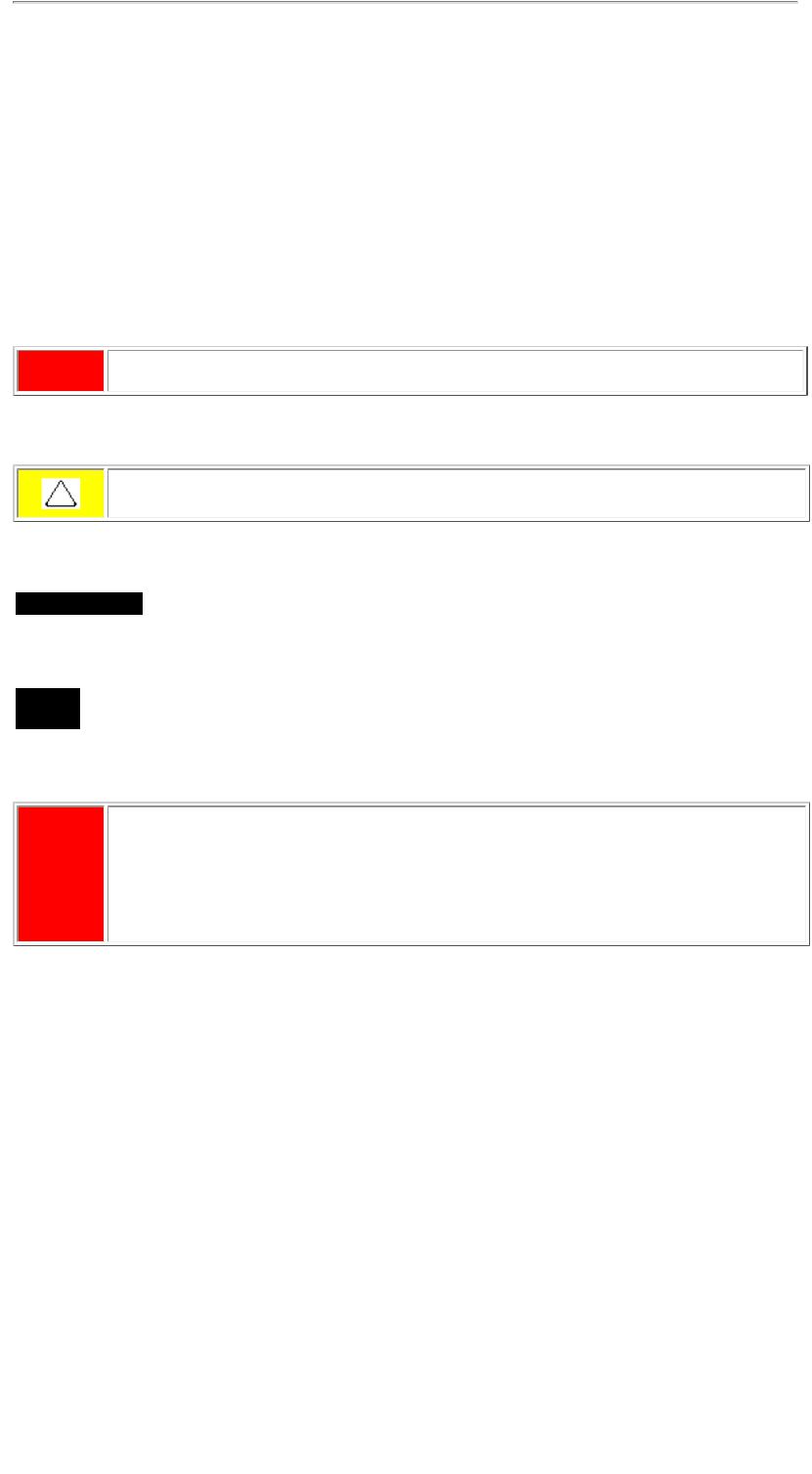
The Compaq Presario Series Portable Computer is
a continuation of the new generation of multimedia portable computers with an innovative and integrated design, outstanding audio and video, advanced core features, and attractive styling. This fullfunction, AMD- K6II-based portable computer allows full desktop functionality.
Maintenance & Service Guide
Presario Series
Models: 1246, 1247, 1277, 1278, and 1279
| Home Page | Notice | Preface | Product Description | Troubleshooting Illustrated Parts Catalog | Removal & Replacement Procedures | Specifications Pin Assignments | Battery Pack Operations
Product Description
Models and Features
Models and |
|
|
|
|
|
|
|
Compaq Presario Series Portable Computer Models |
|||||
Features |
|
|||||
|
|
|
|
|
||
|
|
Model 1246 |
|
Model 1247 |
||
|
|
|
|
|||
Controls and |
|
|
||||
|
Display |
12.1" HPA |
|
12.1" HPA |
||
Lights |
|
|
||||
|
|
Processor |
AMD-K6II MMX 400-Mhz |
|
AMD-K6II MMX 400-Mhz |
|
|
|
|||||
Front Bezel |
||||||
Lights |
|
Hard Drive |
4.3-GB |
|
4.3-GB |
|
|
|
|
||||
|
|
|
|
|
|
|
Front Bezel |
|
CD Drive |
24x CD-ROM |
|
24x CD-ROM |
|
Buttons |
|
|
||||
|
Modem |
56.0 Kbps PCI data/fax |
|
56.0 Kbps PCI data/fax |
||
|
|
|
||||
|
||||||
Left Side |
||||||
|
|
|
|
|
||
Components |
|
System |
32-MB |
|
32-MB |
|
|
|
Memory |
|
|
|
|
Right Side |
3800 MAH NiMH |
|
3800 MAH NiMH |
|||
|
Battery |
|
||||
Components |
|
|
||||
|
|
|
|
|
|
|
|
|
|
|
|
|
|
Bottom of |
|
|
|
|
|
|
Unit |
|
|
|
|
|
|
|
|
Model 1277 |
|
Model 1278 |
||
|
|
Display |
13.0" HPA |
|
12.1" HPA |
|
Rear |
||||||
Connectors |
|
Processor |
|
|
AMD-K6II MMX 433-Mhz |
|
|
|
|
AMD-K6II MMX 400-Mhz |
|
|
|
Power |
|
|
|
|
||
Management |
|
|
(or) |
|
|
|
for Windows |
|
|
AMD-K6II MMX 433-Mhz |
|
|
|
|
|
|
|
|
||
98 |
|
|
|
|
|
|
|
|
Hard Drive |
4.8-GB |
|
4.8-GB |
|
|
||||||
|
|
CD Drive |
24x CD-ROM |
|
24x CD-ROM |
|
|
|
Modem |
56.0 Kbps PCI data/fax |
|
56.0 Kbps PCI data/fax |
|
|
|
System |
64-MB |
|
64-MB |
|
|
|
Memory |
|
|
|
|
|
|
Battery |
3200 MAH sLION |
|
3200 MAH sLION |
|
|
|
|
|
|
|
|
|
|
|
|
|
|
|
|
|
|
|
|
|
|
|
|
|
Model 1279 |
|
|
|
|
|
Display |
12.1" HPA |
|
|
|
|
|
Processor |
|
|
|
|
AMD-K6II MMX 433-
Mhz
Hard Drive |
4.8-GB |
CD Drive |
24x CD-ROM |
Modem |
56.0 Kbps PCI data/fax |
System |
64-MB |
Memory |
|
Battery |
3200 MAH sLION |
|
|
|
|
Maintenance & Service Guide
Presario Series
Models: 1246, 1247, 1277, 1278, and 1279
| Home Page | Notice | Preface | Product Description | Troubleshooting Illustrated Parts Catalog | Removal & Replacement Procedures | Specifications Pin Assignments | Battery Pack Operations
Product Description
Controls and Lights
Models and
Features
Controls and
Lights
Front Bezel
Lights
Front Bezel
Buttons
Left Side
Components
Right Side
Components
Bottom of
Unit
Rear
Connectors
Power Management for Windows 98
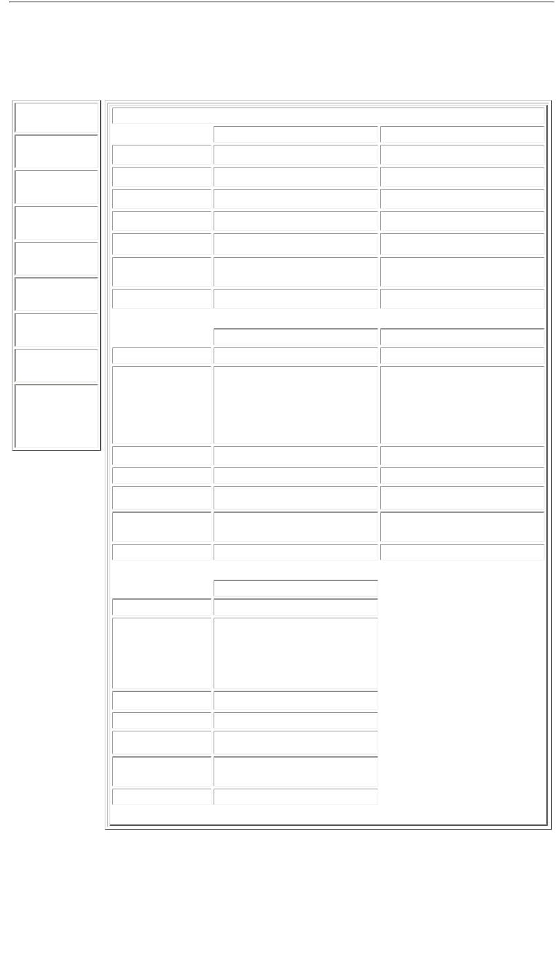
 1. Display
2. Power (On/Off) Button
3. Keyboard
4.Touch Pad
5.Touch Pad Button (Left)
6. Headphone Jack
7. Microphone Jack
8. Touch Pad Button (Right)
9. Integrated Speakers and Ports
Maintenance & Service Guide
Presario Series
Models: 1246, 1247, 1277, 1278, and 1279
| Home Page | Notice | Preface | Product Description | Troubleshooting Illustrated Parts Catalog | Removal & Replacement Procedures | Specifications Pin Assignments | Battery Pack Operations
Product Description
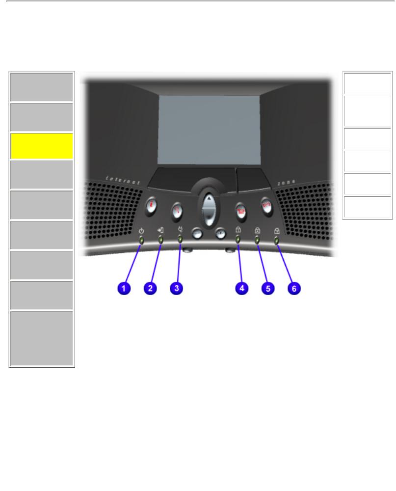
Front Bezel Lights
Models and
Features
Controls
and Lights
Front Bezel
Lights
Front Bezel
Buttons
Left Side
Components
Right Side
Components
Bottom of
Unit
Rear
Connectors
Power Management for Windows 98
1.Power
Light
2.Battery
Charge
Light
3.Power
Cord Light
4.Num Lock Light
5.Cap Lock
Light
6.Scroll Lock Light
Maintenance & Service Guide
Presario Series
Models: 1246, 1247, 1277, 1278, and 1279
| Home Page | Notice | Preface | Product Description | Troubleshooting Illustrated Parts Catalog | Removal & Replacement Procedures | Specifications Pin Assignments | Battery Pack Operations
Product Description
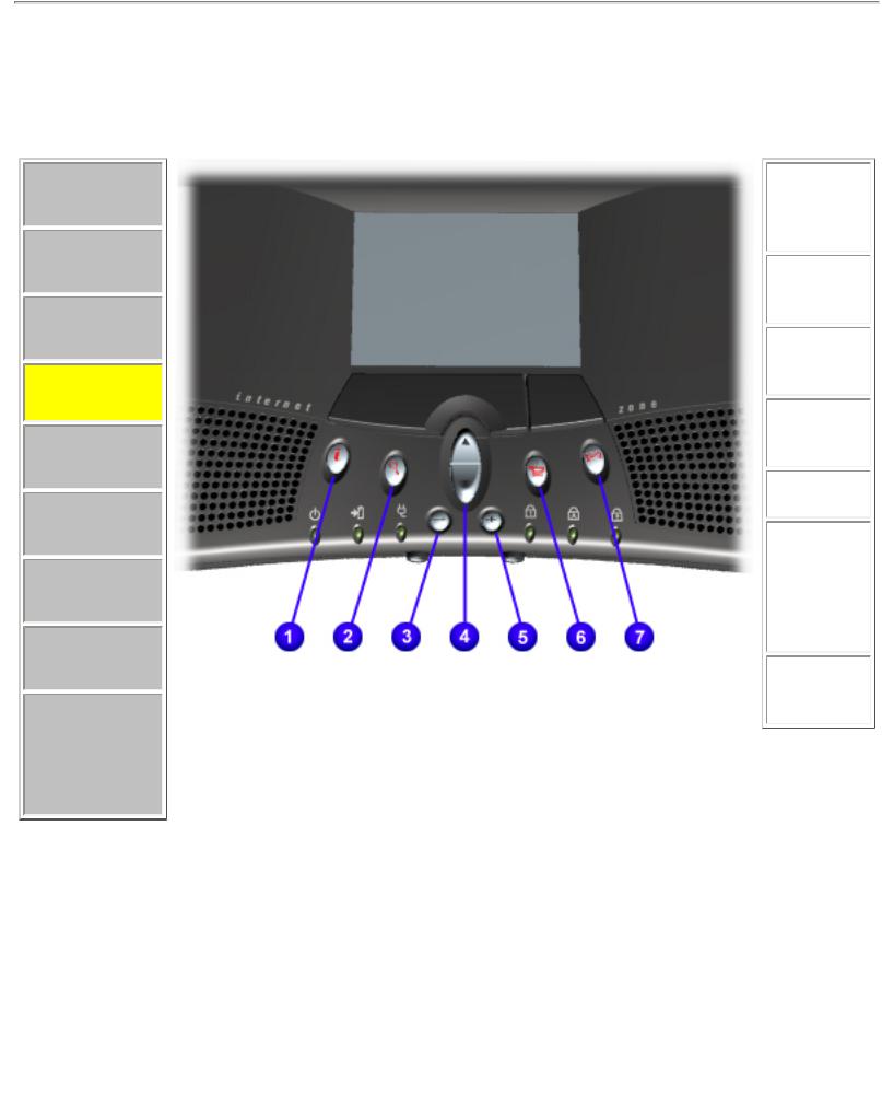
Front Bezel Buttons
Models and
Features
Controls
and Lights
Front Bezel
Lights
Front Bezel
Buttons
Left Side
Components
Right Side
Components
Bottom of
Unit
Rear
Connectors
Power Management for Windows 98
1.Instant Internet Access Button
2.Instant Search Button
3.Volume Down Button
4.Scroll Up/Down Button
5.Volume Up Button
6.Secure
E- Commerce Button
(or favorite Web site)
7.Instant E-Mail Button
Maintenance & Service Guide
Presario Series
Models: 1246, 1247, 1277, 1278, and 1279
| Home Page | Notice | Preface | Product Description | Troubleshooting Illustrated Parts Catalog | Removal & Replacement Procedures | Specifications Pin Assignments | Battery Pack Operations
Product Description
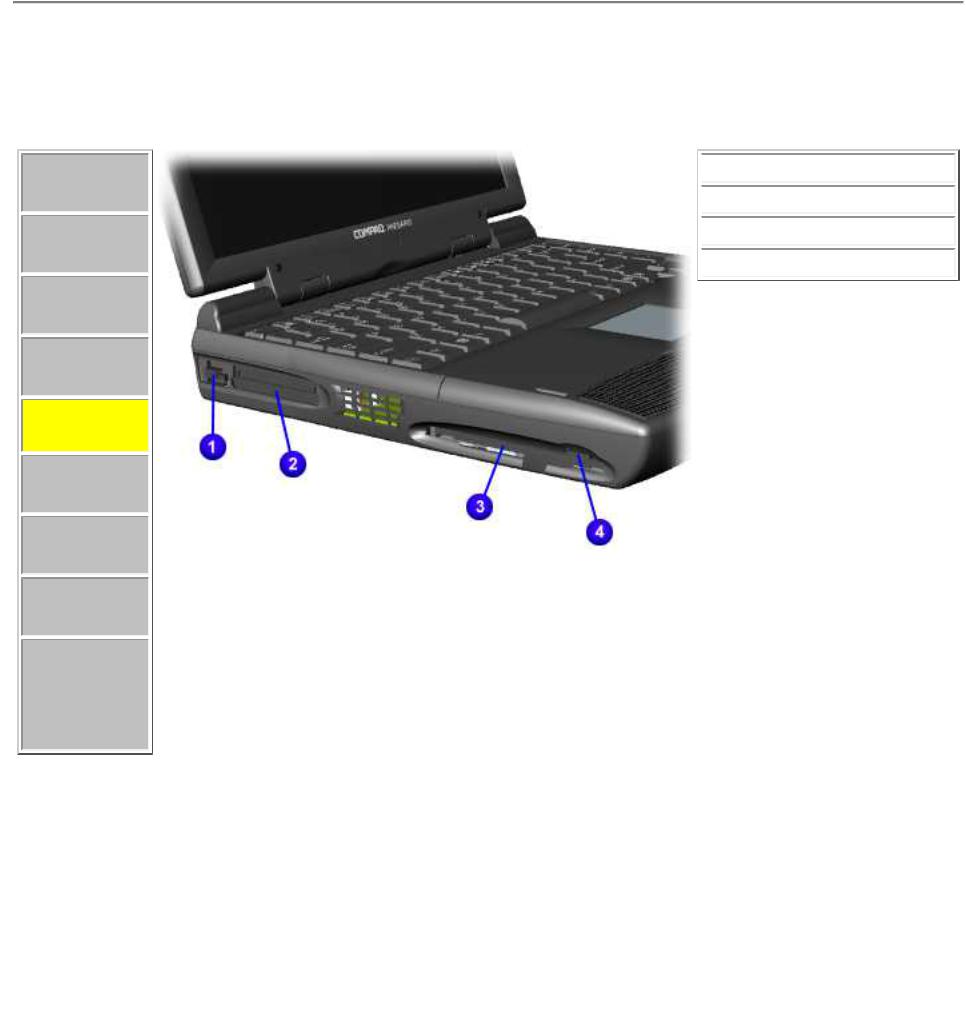
Left Side Components
Models and
Features
Controls
and Lights
Front Bezel
Lights
Front Bezel
Buttons
Left Side
Components
Right Side
Components
Bottom of
Unit
Rear
Connectors
Power Management for Windows 98
 1. PC Card Eject Lever
 2. PC Card Slot
 3. Diskette Drive Slot
 4. Diskette Eject Button
Maintenance & Service Guide
Presario Series
Models: 1246, 1247, 1277, 1278, and 1279
| Home Page | Notice | Preface | Product Description | Troubleshooting Illustrated Parts Catalog | Removal & Replacement Procedures | Specifications Pin Assignments | Battery Pack Operations
Product Description
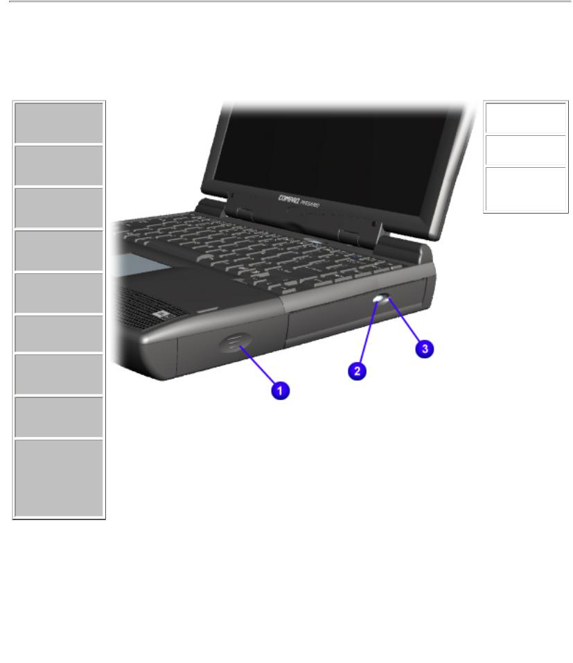
Right Side Components
Models and
Features
Controls
and Lights
Front Bezel
Lights
Front Bezel
Buttons
Left Side
Components
Right Side
Components
Bottom of
Unit
Rear
Connectors
Power Management for Windows 98
1.Battery Compartment
2.CD Drive Eject Button
3.CD Drive Manual Eject Hole
Maintenance & Service Guide
Presario Series
Models: 1246, 1247, 1277, 1278, and 1279
| Home Page | Notice | Preface | Product Description | Troubleshooting Illustrated Parts Catalog | Removal & Replacement Procedures | Specifications Pin Assignments | Battery Pack Operations
Product Description
Models and
Features
Controls and
Lights
Front Bezel
Lights
Front Bezel
Buttons
Left Side
Components
Right Side
Components
Bottom of Unit
Rear Connectors
Power
Management for
Windows 98
Bottom of
Unit
1. Memory
Compartment
Door
 2. Stand Feet
Maintenance & Service Guide
Presario Series
Models: 1246, 1247, 1277, 1278, and 1279
| Home Page | Notice | Preface | Product Description | Troubleshooting Illustrated Parts Catalog | Removal & Replacement Procedures | Specifications Pin Assignments | Battery Pack Operations
Product Description
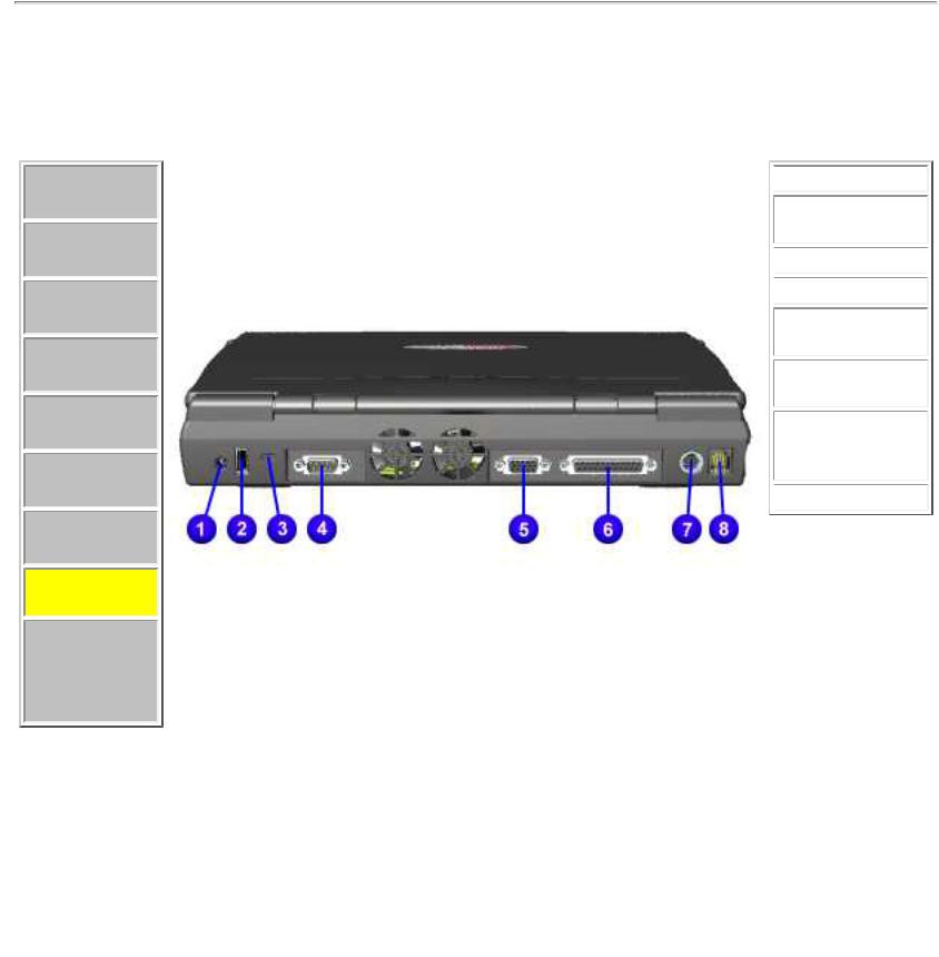
Rear Connectors
Models and
Features
Controls and
Lights
Front Bezel
Lights
Front Bezel
Buttons
Left Side
Components
Right Side
Components
Bottom of
Unit
Rear
Connectors
Power Management for Windows 98
 1. AC Adapter
2. Universal
Serial Bus
 3. Security Slot
 4. Serial Port
5.External Monitor Port
6.Parallel Printer Port
7.
Keyboard/Mouse Port
 8. Modem Jack

Maintenance & Service Guide
Presario Series
Models: 1246, 1247, 1277, 1278, and 1279
| Home Page | Notice | Preface | Product Description | Troubleshooting Illustrated Parts Catalog | Removal & Replacement Procedures | Specifications Pin Assignments | Battery Pack Operations
Power Management for Windows 98
The following power management features are available for conserving AC power and extending battery operating time:
●Power Management Settings
●Sleep
●Hibernation
●Battery operating time
●Rebooting After a Lockup
●Servicing Your Computer - Full Off Mode
Pow
er Management Settings
Depending on your patterns of computer use, you can set different levels of power management. These different power management levels can be activated based on the amount of time passed since the last system activity. System activity examples include keyboard or mouse movement, CD playback (while under program control that monitors Sleep), and modem use.
You can select different conditions or power schemes through Power Management.The optional settings are Home/Office Desk, Portable/ Laptop, and Always On. From the default settings, you can change the following settings:
●the System goes to Sleep (Standby) mode
●the screen times out and goes blank
●the hard drive spins down
Each of these system components goes to sleep after the selected or default periods of inactivity. (The setting for hard drive must be less than, or equal to, the setting for System.)
IMPORTANT: If you're on a network, it's recommended that you set System Standby to
Never.
There are five categories of power management settings under the Control Panel. The default setting for each feature is listed below in the tables.
Power Management Properties
Tab: Power Schemes: |
Plugged in |
Running on Batteries |
|
|
|
Always on System Standby: |
Never |
15 minutes |
|
|
|
Turn OFF Monitor |
After 3 hours |
Never |
|
|
|
Always on System Standby: |
After 15 minutes |
After 10 minutes |
|
|
|
Power Management Properties
 Tab: Alarms:
Low Battery Alarm: |
10% |
|
|
|
|
Critical Battery Alarm: |
0% |
|
|
|
|
|
|
|
Alarm Actions: |
X Display Message Notification |
|
|
Text Action |
No Action |
|
|
|
Power Management Properties
 Tab: Power Meter:
 Tab: Advanced:
 Default
 Default
Display Properties
 Tab: Monitor: Laptop Display (Maximum resolution according to unit display size)
Sleep
You can select Sleep mode instead of turning off the computer when you have finished using it. This allows the computer to wake up faster than turning it completely off and saves power over the active (On) mode.
Compaq Presario Series Notebook computers have two levels of sleep-- Hibernation and Sleep.
Hibernation - by pushing the power button once, your computer performs a save to disk followed by a shut down of the computer into Off mode.
Sleep - is a low power mode, also referred to as Standby mode. While in Sleep mode, your computer maintains system information and open files. Unsaved information is lost if you turn off your system prior to system wake-up, or if you lose power while using the AC adapter.
CAUTION: While in Sleep mode, your computer maintains system information and open files. Unsaved information is lost if you turn off your system prior to system wake-up, or if you lose power while using the AC adapter.
Hibernation Mode
Hibernation helps conserve battery life and protects your data. Hibernation can be a routine power-saving event, or can be the result of a low-battery condition. As it enters Hibernation your computer displays a progress screen, as it automatically saves the machine state before it shuts down and turns itself off. Your computer automatically goes into Hibernation when the battery has little power left, or when the system (operating on battery power) has been in Sleep mode for more than an hour. You can also manually initiate Hibernation by pressing the power button once while the system is active. To restore the computer's previous state, simply press the power button once again. While waking up, the computer displays a progress screen.
The following table shows the conditions and indicators for getting in and out of the various power management modes - Sleep, Hibernation, and Off.
Mode |
|
To Initiate |
|
To End |
|
Indicators |
Sleep |
|
Manual keys combination- |
|
Press any |
|
Flashing green Power |
|
|
Fn+F4 |
|
key |
|
LED |
|
|
Time Out Default 15 minutes. If |
|
|
|
|
|
|
on Battery power (system will |
|
|
|
|
|
|
not go to Sleep if on AC power) |
|
|
|
|
Hibernate |
|
Manual - Press Power button |
|
Press Power |
|
No Power LED, blank |
|
|
once |
|
button once |
|
screen |
Time Out Default If low battery or after 1 hour of sleep (system will not Hibernate if on AC power)
Off |
Perform normal Windows |
Press Power |
No Power LED, blank |
|
shutdown via the start button, or button once |
screen |
|
|
press and hold down the power |
|
|
|
button for 4 seconds |
|
|
Servicing Your Computer - Full Off Mode
If you need to install or replace components in your system, you must turn the computer off completely. Follow the instructions above for properly placing the computer into Off mode. Then, unplug the computer from the
AC outlet and remove the battery (see battery section for instruction for removing the battery pack).
Rebooting After a Lockup
Occasionally you may encounter a frozen keyboard or a locked screen. To reboot your computer (as if from
a cold start) press and hold down the Power Button for at least four seconds, which will cause a manual shutdown. Then, restart it with a single press of the Power Button. If it still doesn't recover, do the following:
1.Press the Power Button and hold it for four seconds to shut it down.
2.Remove the battery or unplug the AC power for at least 30 seconds.
3.Reinsert the battery or reconnect AC power.
4.Press the Power Button once to reboot.
Battery Operating Time
Battery operating time is affected by variables, such as the following:
●Power conservation settings
●Hardware configuration
●Software applications
●Installed options
●Display brightness
●Hard drive usage
●Power button
●Changes in operating temperature
●Type and number of installed PC Cards
For more information on increasing battery pack operating time, conditioning the battery pack, and disposing of a used battery pack, refer to the Battery Pack Operations.
Top of Page
Maintenance & Service Guide
Presario Series
Models: 1246, 1247, 1277, 1278, and 1279
| Home Page | Notice | Preface | Product Description | Troubleshooting Illustrated Parts Catalog | Removal & Replacement Procedures | Specifications Pin Assignments | Battery Pack Operations
Troubleshooting
Preliminary
Steps
Clearing the
Power-On
Password
Power-On Self
Test (POST)
Compaq
Diagnostics
Diagnostic Error
Codes
Troubleshooting
Without
Diagnostics
Solving Minor
Problems
Contacting
Compaq
Support
This section covers troubleshooting information for the Compaq Presario Series Portable Computers. The basic steps in troubleshooting include:
1.Follow the Preliminary Steps.
2.Run the Power-On Self-Test (POST).
3.Follow the recommended actions described in the diagnostic tables, if you are unable to run POST or if POST displays an error message.
When following the recommended actions in the Sections on POST and Diagnostic Error Codes perform them in the order
listed. Rerun POST after each recommended action until the problem is solved and no error message occurs. Once the problem is solved, do not complete the remaining recommended actions.
NOTE: If the problem is intermittent, check the computer several times to verify that the problem is solved.
Maintenance & Service Guide
Presario Series
Models: 1246, 1247, 1277, 1278, and 1279
| Home Page | Notice | Preface | Product Description | Troubleshooting Illustrated Parts Catalog | Removal & Replacement Procedures | Specifications Pin Assignments | Battery Pack Operations
Troubleshooting
Preliminary Steps
Preliminary
Steps
Clearing the
Power-On
Password
Power-On Self
Test (POST)
Compaq
Diagnostics
Diagnostic Error
Codes
Troubleshooting
Without
Diagnostics
Solving Minor
Problems
Contacting
Compaq
Support
Before running POST, complete the following preliminary steps:
1.If a power-on password has been established, type the password and press the Enter key. If the password is not known, clear the password .
2.Run Computer Checkup.
3.Turn off the computer and its external devices.
4.Disconnect any external devices that you do not want to test. Do not disconnect the printer if you want to test it or use it to log error messages.
IMPORTANT:
IMPORTANT: If the problem only occurs when an external device is connected to the computer, the problem may be related to the external device or its cable. Verify this by running POST with and without the external device connected.
5.Install loopback plugs in the serial and parallel connectors if you would like to test these ports.
6.Ensure the hard drive is installed in the computer.
7.Ensure that the battery pack is inserted in the computer and the computer is connected to an external AC power source.
When the preliminary steps are completed, you are ready to run POST.
Maintenance & Service Guide
Presario Series
Models: 1246, 1247, 1277, 1278, and 1279
| Home Page | Notice | Preface | Product Description | Troubleshooting Illustrated Parts Catalog | Removal & Replacement Procedures | Specifications Pin Assignments | Battery Pack Operations
Troubleshooting
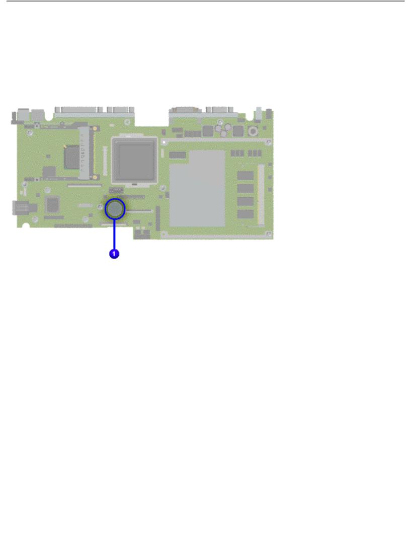
Clearing the Power-on Password
Clearing the power-on password requires removing all Setup attributes that are programmed in the CMOS.
The RTC battery  is located on the system board.
If the password is not known, clear it by performing the following steps:
1. Turn off the computer.
2. Disconnect the power cord.
3. Remove the battery pack.
4. Remove the Palmrest Cover with Touch Pad.
5. Remove the heatspreader.
6. Remove the keyboard.
7. Remove RTC battery for 30 seconds and replace it.
8. Reassemble the computer.
9. Turn on the computer to verify that the power-on password has been cleared. If it has not been cleared, repeat Steps 1 through 9.
Maintenance & Service Guide
Presario Series
Models: 1246, 1247, 1277, 1278, and 1279
| Home Page | Notice | Preface | Product Description | Troubleshooting Illustrated Parts Catalog | Removal & Replacement Procedures | Specifications Pin Assignments | Battery Pack Operations
Troubleshooting
Power-On Self Test (POST)
Running POST
To run POST, turn off the computer. Then turn on the computer.
If POST does not detect any errors, the computer will not beep. This indicates successful completion of POST test. POST has run successfully and boots from the hard drive (or from a bootable diskette if one is installed in the diskette drive).
If POST detects errors, the errors are indicated by screen and/or audible messages. Refer to "Power-On Self-Test (POST) Codes" in the tables for a list of POST codes and their relevant descriptions.
If the system is not functioning well enough to run POST, or if the display is not NOTE: functioning well enough to show POST error messages, refer to the Troubleshooting
tables.
NOTE: The following routines are sorted by their test point numbers assigned in the BIOS code. Their actual orders, as executed during POST, can be quite different.
Code |
Beeps |
02h |
|
03h |
|
04h |
|
06h |
|
08h |
|
09h |
|
0Ah |
|
0Bh |
|
0Ch |
|
0Eh |
|
0Fh |
|
10h |
|
11h |
|
12h |
|
13h |
|
14h |
|
16h |
1-2-2-3 |
17h |
|
18h |
|
1Ah |
|
1Ch |
|
20h |
1-3-1-1 |
22h |
1-3-1-3 |
24h |
|
26h |
|
28h |
|
29h |
|
2Ah |
|
2Ch |
1-3-4-2 |
2Eh |
1-3-4-3 |
2Fh |
|
30th |
1-4-1-1 |
32h |
|
33h |
|
36h |
|
38h |
|
3Ah |
|
3Ch |
|
3Dh |
|
42h |
|
45h |
|
46h |
2-1-2-3 |
48h |
|
49h |
|
4Ah |
|
4Bh |
|
4Ch |
|
4Eh |
|
50Eh |
|
51h |
|
52h |
|
54h |
|
58h |
2-2-3-1 |
59h |
|
5Ah |
|
5Bh |
|
5Ch |
|
60h |
|
62h |
|
64h |
|
66h |
|
67h |
|
68h |
|
69h |
|
6Ah |
|
6Bh |
|
6Ch |
|
6Eh |
|
70h |
|
72h |
|
76h |
|
7Ch |
|
7Eh |
|
80h |
|
81h |
|
82h |
|
83h |
|
84h |
|
85h |
|
86h |
|
87h |
|
88h |
|
89h |
|
8Ah |
|
8Bh |
|
8Ch |
|
81h |
|
90h |
|
91h |
|
92h |
|
93h |
|
95h |
|
96h |
|
97h |
|
98h |
1-2 |
99h |
|
9Ah |
|
9Ch |
|
9Dh |
|
9Eh |
|
9Fh |
|
A0h |
|
A2h |
|
A4h |
|
A8h |
|
AAh |
|
ACh |
|
AEh |
|
B0h |
|
B2h |
|
B4h |
1 |
B5h |
|
B6h |
|
B9h |
|
BAh |
|
BBh |
|
BCh |
|
BDh |
|
BEh |
|
BFh |
|
C0h |
|
C1h |
|
C2h |
|
C3h |
|
C4h |
|
C5h |
|
C6h |
|
C7h |
|
C8h |
|
C9h |
|
D2h |
|
 POST Routine Description
 Verify Real Mode
 Disable Non-Maskable Interrupt (NM)
 Get CPU type
 Initialize system hardware
 Initialize chipset with Initial POST values
 Set IN POST flag
 Initialize CPU registers
 Enable CPU cache
 Initialize caches to initial POST values
 Initialize I/O component
 Initialize the local bus IDE
 Initialize Power Management
 Load alternate registers with initial POST values
 Restore CPU control word during warm boost
 Initialize PCI Bus Mastering devices
 Initialize keyboard controller
 BIOS ROM Checksum
 Initialize cache before memory autosize
 8254 timer initialization
 8237 DMA controller initialization
 Reset Programmable Interrupt Controller
 Test DRAM refresh
 Test 8742 Keyboard Controller
 Set ES segment register to 4 GB
 Enable A20 line
 Autosize DRAM
 Initialize POST Memory Manager
 Clear 512 KB base RAM
 RAM failure on address line xxxx*
RAM failure on data bits xxxx* of low byte of memory bus
 Enable cache before system BIOS shadow
RAM failure on data bits xxxx*of high byte memory bus
 Test CPU bus-clock frequency
 Initialize Phoenix Dispatch Manager
 Warm start shut down
 Shadow system BIOS ROM
 Autosize cache
 Advanced configuration of chipset registers
 Load alternate registers with CMOS values
 Initialize interrupt vectors
 POST device initialization
 Check ROM copyright notice
 Check Video configuration against CMOS
 Initialize PCI bus and devices
 Initialize all video adapters in system
 QuietBoot start (optional)
 Shadow video BIOS ROM
 Display BIOS copyright notice
 Display CPU type and speed
 Initialize EISA board
 Test keyboard
 Set key click if enabled
 Test for unexpected interrupts
 Initialize POST display service
 Display prompt "Press F2 to enter SetUP"
 Disable CPU cache
 Test RAM between 512 and 640 KB
 Test extended memory
 Test extended memory address lines
 Jump to UserPatchI
 Configure advanced cache registers
 Initialize Multi Processor APIC
 Enable external and CPU cache
 Setup System Management Mode (SMM) area
 Display external L2 cache size
 Load custom defaults (optional)
 Display shadow-area message
 Display possible high address for UMB recovery
 Display error messages
 Check for configuration errors
 Check for keyboard errors
 Set up hardware interrupt vectors
 Initialize coprocessor if present
 Disable onboard Super I/O ports and IRQs
 Late POST device initialization
 Detect and install external RS232 ports
 Configure non-MCD IDE controllers
 Detect and install external parallel ports
 Initialize PC-compatible PnP ISA devices
 Reinitialize onboard I/O ports
 Configure Motherboard Configurable Devices (optional)
 Initialize BIOS Data Area
 Enable Non-Maskable Interrupts (NMIs)
 Initialize Extended BIOS Data Area
 Test and initialize PS/2 mouse
 Initialize floppy controller
 Determine number of ATA drives (optional)
 Initialize hard disk controllers
 Initialize local-bus hard disk controllers
 Jump to UserPatch2
 Build MPTABLE for multi-processor boards
 Install CD ROM for boot
 Clear huge ES segment register
 Fixup Multi Processor table
Search for option ROMs. One long, two short beeps on checksum failure
 Check for SMART drive (optional)
 Shadow option ROMs
 Set up Power Management
 Initialize security engine (optional)
 Enable hardware interrupts
 Determine number of ATA and SCSI drives
 Set time of day
 Check key lock
 Initialize Typematic rate
 Erase F2 prompt
 Scan for F2 key stroke
 Enter Setup
 Clear Boot flag
 Check for errors
 POST done - prepare to boot operating system
 One shot beep before boot
 Terminate QuietBoot (optional)
 Check password (optional)
 Prepare Boot
 Initialize DMI Parameters
 Initialize PnP Option ROMs
 Clear parity checkers
 Display MultiBoot menu
 Clear screen (optional)
 check virus and back up reminders
 Try to boot with INT 19
 Initialize POST Error Manager (PEM)
 Initialize error logging
 Initialize error display function
 Initialize system error handler
 PnPnd dual CMOS (optional)
 Initialize notebook docking (optional)
 Initialize notebook docking late
 Force check (optional)
 Extended checksum (optional)
  Unknown interrupts
|
Code |
|
Beeps |
|
For Boost Block in Flash ROM |
|
|
E0h |
|
|
|
|
Initialize the chipset |
|
E1h |
|
|
|
|
Intitialize the bridge |
|
E2h |
|
|
|
|
Initialize the CPU |
|
E3h |
|
|
|
|
Initialize system timer |
|
E4h |
|
|
|
|
Initializesystem I/O |
|
E5h |
|
|
|
|
Check force recovery boot |
|
E6h |
|
|
|
|
Checksum BIOS ROM |
|
E7h |
|
|
|
|
Go to BIOS |
|
E8h |
|
|
|
|
Set Huge Segment |
|
E9h |
|
|
|
|
Initialize Multi Processor |
|
EAh |
|
|
|
|
Initialize OEM Special code |
|
EBh |
|
|
|
|
Initialize PIC and DMA |
|
ECh |
|
|
|
|
Initialize Memory type |
|
EDh |
|
|
|
|
Initialize Memory size |
|
EEh |
|
|
|
|
Shadow Boot Block |
|
EFh |
|
|
|
|
System memory test |
|
F0h |
|
|
|
|
Initialize interrupts vectors |
|
F1h |
|
|
|
|
Initialize Run Time Clock |
|
F2h |
|
|
|
|
Initialize Video |
|
F3h |
|
|
|
|
Initialize beeper |
|
F4h |
|
|
|
|
Initialize boot |
|
F5h |
|
|
|
|
Clear Huge segment |
|
F6h |
|
|
|
|
Boot to Mini DOS |
|
F7h |
|
|
|
|
Boot to Full DOS |
|
|
|
|
|
|
|
|
|
|
|
|
|
|

Maintenance & Service Guide
Presario Series
Models: 1246, 1247, 1277, 1278, and 1279
| Home Page | Notice | Preface | Product Description | Troubleshooting Illustrated Parts Catalog | Removal & Replacement Procedures | Specifications Pin Assignments | Battery Pack Operations
Troubleshooting
Compaq Diagnostics
Compaq Diagnostics is installed on the hard drive of the computer. Run the Diagnostics utilities when you want to view or test system information and if you have installed or connected devices. If you run Compaq Diagnostics from a diskette, ensure that it is version 10.11 or later.
The Diagnostics menu includes the following utilities:
■Computer Checkup (TEST)
■View System Information (INSPECT)
■Prepare Computer for a Compaq Service Call (RemotePaq)
If you have a problem you cannot solve, run the Diagnostics utilities before you call for support. Run Computer Checkup and select to save the device list to a file and to print or to save the error log. Run the View System Information (INSPECT) utility and select to print or to save that information. Have the files or the printed information available when you call for support.
Computer Checkup (TEST)
Computer Checkup (TEST) determines whether the various computer components and devices are recognized by the system and are functioning properly. You can display, print, or save the information generated by
Computer Checkup.
Follow these steps to run Computer Checkup:
1.Plug the computer into an external power source. (A low battery condition could interrupt the program.)
2.Turn on the external devices that you want to test. Connect the printer if you want to print a log of error messages.
3.Insert the Compaq Diagnostics diskette in drive A.
4.Turn on or restart the computer. The computer starts from drive A, and the
Diagnostics Welcome screen appears.
5.Press Enter to continue. The Diagnostics menu appears.
6.Select Computer Checkup from the Diagnostics menu. A Test Option menu appears.
7.Select View the Device List from the Test Option menu. A list of the installed Compaq devices appears.
8.If the list of installed devices is correct, select OK. The Test Option menu appears.
NOTE: If the list is incorrect, ensure that any new devices are installed properly.
9.Select one of the following from the Test Option menu:
■Quick Check Diagnostics. Runs a quick, general test on each device with a minimal number of prompts.
If errors occur, they display when the testing is complete. You cannot print or save the error messages.
■Automatic Diagnostics. Runs unattended, maximum testing of each device with minimal prompts.
You can choose to run the tests for a specified number of times, to stop on errors, or to print or save an error log.
■Prompted Diagnostics. Allows maximum control over testing the devices. You can choose attended or unattended testing, decide to stop on errors, or choose to print or save an error log.
10.Follow the instructions on the screen as the devices are tested. When testing is complete,
the Test Option menu appears.
11.Exit the Test Option menu.
12.Exit the Diagnostics menu.
View System Information (INSPECT)
The View System Information (INSPECT) utility provides information about the computer and installed or connected devices. You can display, print, or save the information.
Follow the steps listed below to run View System Information (INSPECT) from the Compaq Diagnostics diskette:
1.Turn on the external devices that you want to test. Connect the printer if you want to print the information.
2.Insert the Compaq Diagnostics diskette in drive A.
3.Turn on or restart the computer. The computer starts from drive A, and the
Diagnostics Welcome screen appears.
4.Press Enter to continue. The Diagnostics menu appears.
5.Select View System Information (INSPECT) from the Diagnostics menu.
6.Select the item you want to view from the following list:
System |
Memory |
ROM |
Audio |
Keyboard |
Operating system |
System ports |
System files |
System storage |
Windows files |
Graphics |
|
7. Follow the instructions on the screen to cycle through the screens, to return to the list and choose another item, or to print the information.

Maintenance & Service Guide
Presario Series
Models: 1246, 1247, 1277, 1278, and 1279
| Home Page | Notice | Preface | Product Description | Troubleshooting Illustrated Parts Catalog | Removal & Replacement Procedures | Specifications Pin Assignments | Battery Pack Operations
Troubleshooting
Contacting Compaq Support
Obtain the following information before contacting Compaq Reseller Support:
●Product name
●Product serial number
●Purchase date
●Conditions under which the problem occurred
●Any error messages that have occurred
●Hardware configuration
●Type of printer connected
●Hardware/software being used
●Printed result of Computer Checkup (TEST)
●Printed copies of CONFIG.SYS and AUTOEXEC.BAT files, if possible
Shipping Preparation
To ship the computer, complete the following steps:
1. Back up the critical hard drive files. Ensure that backup tapes/diskette are not exposed to electrical or magnetic fields while stored in transit.
2.Turn off the computer and external devices.
3.Disconnect the external devices from their power sources, then from the computer.
Ensure that there is no diskette in the diskette drive and that there are no PC
IMPORTANT: Cards in the PC slots.
4.Close the display and all exterior doors of the computer.
5.Pack the computer with sufficient packing material to protect it. Use the original packing box or similar packaging.
Maintenance & Service Guide
Presario Series
Models: 1246, 1247, 1277, 1278, and 1279
| Home Page | Notice | Preface | Product Description | Troubleshooting Illustrated Parts Catalog | Removal & Replacement Procedures | Specifications Pin Assignments | Battery Pack Operations
Troubleshooting
Diagnostic Error Codes
Diagnostic error codes occur if the system recognizes a problem while running the Compaq Diagnostic program. These error codes help identify possibly defective subassemblies.
The following tables list error codes, a description of the error condition, and the action required to resolve the error condition.
IMPORTANT: Retest the system after completing each step. When a step resolves the problem, do not
proceed with the remaining steps.
For the removal and replacement of a particular subassembly, see Removal and Replacement Procedures.
Select error codes by number or type:
101 through 114 |
Processor Test |
200 through 215 |
Memory Test |
300 through 304 |
Keyboard Test |
401 through 403 |
Parallel Printer Test |
501 through 516 |
Video Test |
600 through 699 |
Diskette Drive Test |
1101 |
Serial Test |
1701 through 1736 |
Hard Drive Test |
2402 through 2480 |
Video Test |
3206 |
Audio Test |
8601 through 8602 |
TouchPad/Pointing Device interface Test |
3301 through 6623 |
CD Drive Test |
Processor Test Error Codes
Error Code |
Description |
|
Recommended Action |
|
|
|
|||
101-xx |
CPU test failed |
Replace the processor and retest. |
||
102-xx |
Coprocessor or Weitek Error |
1. |
Run the Configuration and Diagnostics |
|
|
|
Utilities. |
||
|
|
2. |
Replace the processor board and retest. |
|
103-xx |
DMA page registers test failed. |
Replace the system board and retest. |
||
104-xx |
Interrupt controller master test failed. |
|
|
|
105-xx |
Port 61 error |
|
|
|
106-xx |
Keyboard controller self-test failed. |
|
|
|
107-xx |
CMOS RAM test failed. |
|
|
|
108-xx |
CMOS interrupt test failed. |
|
|
|
109-xx |
CMOS clock test failed. |
|
|
|
110-xx |
Programmable timer load data test failed. |
|
|
|
113-xx |
Protected mode test failed. |
|
|
|
114-01 |
Speaker test failed. |
1. |
Check system configuration. |
|
|
|
2. |
Verify cable connections to speaker. |
|
|
|
3. |
Replace the system board and retest. |
|
|
|
|||
|
Memory Test Error Codes |
|||
200-xx |
Memory machine ID test failed. |
1. |
Flash the system ROM and retest. |
|
202-xx |
Memory system ROM checksum failed. |
2. |
Replace the system board and retest. |
|
|
|
|||
203-xx |
Write/Read test failed. |
1. |
Remove the memory module and retest. |
|
204-xx |
Address test failed. |
2. |
Install a new memory module and retest. |
|
211-xx |
Random pattern test failed. |
|||
|
|
|||
214-xx |
Noise test failed. |
|
|
|
215-xx |
Random address test failed. |
|
|
|
|
|
|||
|
Keyboard Test Error Codes |
|||
300-xx |
Failed ID Test |
1. |
Check the keyboard connection. |
|
301-xx |
Failed Selftest/Interface Test |
If disconnected, turn off the computer and |
||
connect the keyboard. |
||||
302-xx |
Failed Individual Key Test |
2. |
Replace the keyboard and retest. |
|
|
|
|||
304-xx |
Failed Keyboard Repeat Test |
3. |
Replace the system board and retest. |
|
|
|
|||
|
|
|||
|
Parallel Printer Test Error Codes |
|||
401-xx |
Printer failed or not connected |
1. |
Connect the printer. |
|
|
|
2. |
Check power to the printer. |
|
402-xx |
Failed Port Test |
|
|
|
|
|
3. |
Install the loop-back connector and retest. |
|
403-xx |
Failed Printer Pattern Test |
4. |
Check port and IRQ configuration. |
|
|
|
5. |
Replace the system board and retest. |
|
Video Test Error Codes (501-xx through 516-xx)
 501-xx
 502-xx
 503-xx
 504-xx
 505-xx
 506-xx
 507-xx
 508-xx
 509-xx
 510-xx
 511-xx
 512-xx
 514-xx
  516-xx
 600-xx
 601-xx
 602-xx
 603-xx
 604-xx
 605-xx
 606-xx
 609-xx
 610-xx
 697-xx
 698-xx
699-xx
Failed Video Controller Test |
1. |
Disconnect external monitor and test with |
|
Failed Video Memory Test |
internal LCD display. |
||
|
|
||
Failed Video Attribute Test |
2. |
Replace the display assembly and retest. |
|
Failed Video Character Set Test |
|||
|
|
||
Failed Video 80 x 25 mode 9 x 14 Character Cell |
3. |
Replace the system board and retest. |
|
Test |
|
|
|
Failed Video 80 x 25 mode 8 x 8 Character Cell |
|
|
|
Test |
|
|
|
Failed Video 40 x 25 Mode Test |
|
|
|
Failed Video 320 x 200 Mode Color Set 0 Test |
|
|
|
Failed Video 320 x 200 Mode Color Set 1 Test |
|
|
|
Failed Video 640 x 200 Mode Test |
|
|
|
Failed Video Screen Memory Page Test |
|
|
|
Failed Video Gray Scale Test |
|
|
|
Failed Video White Screen Test |
|
|
|
Failed Video Noise Pattern Test |
|
|
|
Diskette Drive Test |
|
||
Failed Diskette ID Drive Types Test |
1. |
Replace the diskette media and retest. |
|
Failed Diskette Format |
2. |
Check and/or replace the diskette power |
|
Failed Diskette Read Test |
and signal cables and retest. |
||
|
|
||
Failed Diskette Write/Read/Compare Test |
3. |
Replace the diskette drive and retest. |
|
Failed Diskette Random Read Test |
4. |
Replace the system board and retest. |
|
Failed Diskette ID Media |
|
|
|
Failed Diskette Speed Test |
|
|
|
Failed Diskette Reset Controller Test |
|
|
|
Failed Diskette Change Line Test |
|
|
|
Diskette type error |
|
|
|
Diskette drive speed not within limits |
|
|
|
Diskette drive/media ID error |
1. |
Replace media. |
|
|
2. |
Run the Configuration and Diagnostics |
|
|
Utilities. |
||
Serial Test Error Codes
1101-xx |
Failed Serial Port Test |
1. |
Check port configuration. |
|
|
2. |
Replace the system board and retest. |
|
|
|
|
|
|
Hard Drive Test Error Codes |
|
|
|
|
|
1701-xx |
Failed Hard Drive Format Test |
1702-xx |
Failed Hard Drive Read Test |
1703-xx |
Failed Hard Drive Write/Read/Compare Test |
|
|
1704-xx |
Failed Hard Drive Random Seek Test |
1705-xx |
Failed Hard Drive Controller Test |
1706-xx |
Failed Hard Drive Ready Test |
1707-xx |
Failed Hard Drive Recalibration Test |
1708-xx |
Failed Hard Drive Format Bad Track Test |
|
|
1709-xx |
Failed Hard Drive Reset Controller Test |
|
|
1710-xx |
Failed Hard Drive Park Head Test |
1715-xx |
Failed Hard Drive Head Select Test |
1716-xx |
Failed Hard Drive Conditional Format Test |
|
|
1717-xx |
Failed Hard Drive ECC* Test |
1719-xx |
Failed Hard Drive Power Mode Test |
1724-xx |
Failed Network Preparation Test |
1736-xx |
Failed Drive Monitoring Test |
 *ECC = Error Correction Code
1. Run the Configuration and Diagnostics  Utilities and verify drive type.
2. Verify that all secondary drives have secondary drive capability.
 3. Replace the hard drive and retest.
 4. Replace the system board and retest.
Video Test Error Codes (2402-xx through 2480-xx)
 2402-xx
 2403-xx
 2404-xx
 2405-xx
 2406-xx
 2408-xx
 2409-xx
 2410-xx
 2411-xx
 2412-xx
 2414-xx
 2416-xx
 2418-xx
 2419-xx
 2421-xx
  2422-xx
2423-xx
2424-xx
2425-xx
2431-xx  2432-xx 2448-xx
 2451-xx 2456-xx
 2458-xx
 2468-xx
 2477-xx
 2478-xx
  2480-xx
 3206-xx
 8601-xx
  8602-xx
 3301-xx
 3305-xx
 6600-xx
 6605-xx
 6608-xx
  6623-xx
 Failed Video Memory Test
 Failed Video Attribute Test
 Failed Video Character Set Test
Failed Video 80 x 25 mode 9 x 14 Character Cell Test
Failed Video 80 x 25 mode 8 x 8 Character Cell Test
 Failed Video 320 x 200 Mode Color Set 0 Test
 Failed Video 320 x 200 Mode Color Set 1 Test
 Failed Video 640 x 200 Mode Test
 Failed Video Screen Memory Page Test
 Failed Video Gray Scale Test
 Failed Video White Screen Test
 Failed Video Noise Pattern Screen
 Failed ECG/VGC Memory Test
 Failed ECG/VGC ROM Checksum Test
 Failed ECG/VGC 640 x 200 Graphics Mode Test
  Failed ECG/VGC 640 x 350 16 Color Set Test Failed ECG/VGC 640 x 350 64 Color Set Test
Failed ECG/VGC Monochrome Text Mode Test
Failed ECG/VGC Monochrome Graphics Mode
Test
Failed 640 x 480 Graphics Test
 Failed 320 x 200 Graphics (256 Color Mode) Test
  Failed Advanced VGA Controller Test
 Failed 132-Column Advanced VGA Test Failed Advanced VGA 256 Color Test
 Advanced VGA BitBLT Test
 Advanced VGA DAC Test
 Advanced VGA Data Path Test
 Advanced VGA BitBLT Test
 Advanced VGA LineDraw Test
1.Run the Configuration and Diagnostics Utilities
2.Replace the display assembly and retest.
3.Replace the system board and retest.
1.Run the Configuration and Diagnostics Utilities.
2.Disconnect external monitor and test with internal LCD display.
3.Replace the display assembly and retest.
4.Replace the system board and retest.
Replace the system board and retest.
Audio Test Error Codes
Audio System Internatl Error |
Replace the system board and retest. |
||
TouchPad/Pointing Device Interface Test Error Codes |
|||
Failed Mouse Test |
1. |
Replace the TouchPad and retest. |
|
Failed Interface Test |
2. |
Replace the system board and retest. |
|
CD Drive Test Error Codes |
|||
Failed CD Drive Read Test |
1. |
Replace the CD and retest. |
|
Failed CD Drive Seek Test |
2. |
Verify that the speakers are connected. |
|
Failed ID Test |
3. |
Verify that drivers are loaded and properly |
|
installed. |
|||
|
|||
Failed Read Test |
4. |
Replace the CD drive and retest. |
|
|
|||
Failed Controller Test |
5. |
Replace the system board and retest. |
|
|
|||
 Failed Random Read Test
Back to top
Maintenance & Service Guide
Presario Series
Models: 1246, 1247, 1277, 1278, and 1279
| Home Page | Notice | Preface | Product Description | Troubleshooting Illustrated Parts Catalog | Removal & Replacement Procedures | Specifications Pin Assignments | Battery Pack Operations
Troubleshooting Without Diagnostics
This section provides information about how to identify and correct some common hardware, memory, and software problems. It also explains several types of common messages that may be displayed on the screen. The following pages contain troubleshooting information on:
 Audio
Audio
 Battery/Battery gauge
 CD drive
 Diskette/Diskette drive
 Display
 Hard drive
 Hardware Installation
 Memory
 PC Card
 Power
Power
 Printer
 Touch Pad
 Keyboard/Numeric Keypad
Since symptoms can appear to be similar, carefully match the symptoms of the computer malfunction against the problem description in the Troubleshooting tables to avoid a misdiagnosis.
WARNING: To avoid a potential shock hazard during troubleshooting procedures, disconnect all power sources before removing the keyboard cover or the display bezel.
Before Replacing Parts
Verify that cables are connected properly to the suspected defective parts.
■Run Computer Setup after connecting external devices.
■Verify that all required device drivers are installed.
■Verify that all required changes have been made to the CONFIG.SYS file.
■Verify that all required changes have been made to the AUTOEXEC.BAT file.
■Verify that all printer drivers have been installed for each application.

Maintenance & Service Guide
Presario Series
Models: 1246, 1247, 1277, 1278, and 1279
| Home Page | Notice | Preface | Product Description | Troubleshooting Illustrated Parts Catalog | Removal & Replacement Procedures | Specifications Pin Assignments | Battery Pack Operations
Troubleshooting Without Diagnostics
Solving Minor Problems
Some minor problems and possible solutions are outlined in the following tables. If the problem appears related to a software application, check the documentation provided with the software.
Solving Audio Problems
Some common audio problems and solutions are listed in the following table.
Solving Audio Problems
 Problem
Computer does not beep after the Power-On
Self-Test (POST).
Probable Cause |
Solution(s) |
This is typical; it indicates successful |
No action is required. |
completion of the Power-On Self-Test |
|
(POST). |
|
Solving Battery Pack and Battery Gauge Problems
Some common causes and solutions for battery pack problems are listed in the following table. The "Solving Power Problems" section in this chapter may also be applicable.
Solving Battery Pack and Battery Gauge Problems
Problem |
Probable Cause |
Solution(s) |
|
Computer won't turn on when battery |
Battery pack is discharged. |
Connect the computer to an external |
|
pack is inserted and power cord is |
|
power source and charge the battery |
|
unplugged. |
|
pack. |
|
|
|
Replace the battery pack with a fully |
|
|
|
charged battery pack. |
|
|
|
Check the battery connectors on the |
|
|
|
system board to verify they are evenly |
|
|
|
spaced and that they are not bent or |
|
|
|
broken. |
|
Computer is beeping and battery LED |
Battery charge is low. |
Immediately save any open file(s). Then |
|
icon is blinking. |
|
do any one of the following: |
|
|
|
● |
Connect the computer to an |
|
|
|
external power source to charge |
|
|
|
the battery pack. |
|
|
● |
Turn off the computer or initiate |
|
|
|
Hibernation until you can find |
another power source or charge the battery pack.
Computer battery LED icon (front on the Volume is turned down too low. unit) blinks to indicate low battery
condition, but computer does not beep.
Battery LED icon doesn't light and |
Battery pack is already charged. |
battery pack won't fast charge. |
|
Battery pack was exposed to temperature extremes.
 Battery pack is at end of its life.
You have to set the date and time every RTC battery is dead. time you turn on the computer.
Problem |
Probable Cause |
Battery charge does not last as long |
Battery is being exposed to high |
as expected. |
temperatures or extremely cold |
|
temperatures. |
Adjust the volume.
 No action is necessary.
Allow time for the battery pack to return to room temperature.
 Replace battery pack.
  Replace the RTC battery.
 Solution(s)
Keep the battery pack within the recommended operating temperature range 50° F to 104° F (10° C to
40° C) or recommended storage range - 4° F to 86° F (-20° C to
30° C ). Recharge the battery pack.
Battery pack is warm to the touch after charging.
Battery pack operating time is far less than the documented average operating time.
Battery has partially self-discharged. |
Recharge the battery. Discharge the |
|
battery completely and then recharge it. |
Power management is disabled. |
Set a power management level in |
|
Computer Setup. |
An external device or PC Card is draining |
Turn off or disconnect external devices |
the battery. |
when not using them. |
Normal warming has occurred due to |
No action is required. |
charging. |
|
Power management is turned off or |
Enable power management in Computer |
disabled. |
Setup and in Windows Power Properties. |
An external device or PC Card is draining the battery.
Battery pack has partially selfdischarged.
Battery pack is being exposed to high temperatures or extremely cold temperatures.
Turn off or disconnect external devices when not using them.
Condition the battery pack by fully charging, fully discharging, then fully recharging it.
To maintain the charge, leave battery packs in the computer when it is connected to external power.
If the computer is disconnected from external power for more than two weeks, remove battery packs from the computer to reduce the discharge rate.
Keep the battery pack within the recommended temperature ranges. Operating: 50° F to 104° F
(10° C to 40° C) Storage: -4° F to 86° F (-20° C to 30° C )
Recharge the battery pack.
Solving CD Drive Problems
Some common causes and solutions for CD drive problems are listed in the following table.
Solving CD Drive Problems
Problem |
Probable Cause |
Solution(s) |
CD drive cannot read a compact disc. |
Compact disc is upside down or is |
Open the CD loading tray, lay the |
|
improperly inserted in the CD drive. |
compact disc in it (label side up), then |
|
|
close the tray. |
|
CD is CD Plus or Pregap/Track 0 type. |
Cannot read these type CDs in 24x. |
|
|
Remove the CD. |
Solving Diskette and Diskette Drive Problems
Some common causes and solutions for diskette and diskette drive problems are listed in the following table.
Solving Diskette and Diskette Drive Problems
Problem |
Probable Cause |
Solution(s) |
Diskette drive cannot write to a diskette. |
Diskette is write-protected. |
Disable the diskette's write-protect |
|
|
feature or use a diskette that is not |
|
|
write-protected. |
 Diskette drive cannot read a diskette.
 Cannot boot from diskette.
Computer is writing to the wrong drive.
Not enough space is left on the diskette.
 Drive error has occurred.
 Diskette is not formatted.
The wrong type of diskette is being used.
 Diskette has a bad sector.
 Drive error has occurred.
Diskette is not formatted.
 Bootable diskette is not in drive A.
Diskette Boot has incorrect setting in Computer Setup.
Check the drive letter in the path statement.
 Use another diskette.
Run Computer Checkup from the Compaq Diagnostics diskette.
Format the diskette. At the system prompt, enter FORMAT A:
Use the type of diskette required by the drive.
Copy files to hard drive or another diskette. Reformat bad floppy.
Run Computer Checkup from the Compaq Diagnostics diskette.
Format the diskette. At the system prompt, enter FORMAT A:
 Put the bootable diskette in drive A.
Run Computer Setup and set diskette as first to boot.
Solving Display Problems
This section lists some common causes and solutions for computer display and external monitor problems.
You can perform a monitor self-test on an external VGA color or monochrome monitor by disconnecting the monitor from the computer. To do so, complete the following steps:
1.Turn off the monitor.
2.Turn off the computer.
3.Disconnect the monitor signal cable from the computer.
4.Turn on the monitor and allow it to warm up for one minute.
The display should be white. A narrow black border may also appear on the left and right sides of the display. Either of these displays indicates that the monitor is working properly.
Solving Display Problems
Problem |
Probable Cause |
Screen is dim. |
Control for brightness or contrast (if |
|
applicable) is not set properly. |
|
Computer screen is in direct light. |
Screen is blank. |
Screen save was initiated by Power |
|
Management due to lack of user |
|
activity. |
 Solution(s)
Adjust the Brightness of the display by
using Fn + F7 (¯ ) or
Fn + F8 (- ).
Adjust the Contrast of the display by using Fn + F5 (¯ ) or
Fn + F6 (- ).
 Tilt display or move computer.
Press any key or touch the Touch Pad.
|
Display has overheated. |
If computer is in direct sunlight, move it |
|
|
and allow it to cool off. |
Display is blank and the Suspend icon is |
System is in Suspend mode. |
Press any key or touch the Touch Pad. |
flashing. |
|
|
Internal display is blank and the screen |
Display function was switched to the |
Use Fn + F2 to switch between LCD or |
on an external monitor displays |
external monitor. |
CRT. |
information. |
|
|
Problem |
Probable Cause |
Solution(s) |
Internal display flashes or has garbled characters when computer is connected to external monitor.
Using 1024 × 768 or higher |
Restart the computer. |
resolution on external monitor |
|
and have toggled back to |
|
internal display, which |
|
supports up to |
|
800 × 600. |
|
The light tubes on the edge of the display panel |
Improper backlight or display |
Replace the display assembly. |
do not light up at all and Power-On Self-Test |
cable connections |
|
(POST) completes when the unit is powered |
|
|
up.** |
|
|
|
Defective inverter board. |
Replace the display assembly. |
|
Defective display cable. |
Replace the display assembly. |
|
Defective display panel. |
Replace the display assembly. |
|
Defective system board. |
Replace the system board. |
The light tubes on the edge of the display panel |
Defective system board. |
Replace the system board. |
do not light up at all and Power-On Self-Test |
|
|
(POST) does not complete when the unit is |
|
|
powered up.** |
|
|
Backlight (brightness) cannot be adjusted with |
Improper display cable |
1. Reseat the display cable to the |
Fn + F7 (¯ ) or |
connections. |
system board. |
Fn + F8 (- ).*** |
|
|
|
|
2. Replace the display assembly. |
|
Defective inverter board. |
Replace the display assembly. |
|
Defective display cable. |
Replace the display assembly. |
|
Defective system board. |
Replace the system board. |
Contrast cannot be adjusted with |
Improper display cable |
1. Reseat the display cable to the |
Fn + F5 (¯ ) or Fn + F6 (- ). |
connections. |
system board. |
|
|
2. Replace the display assembly. |
 Defective inverter board.
 Defective display cable.
  Defective system board.
 Replace the display assembly.
 Replace the display assembly.
  Replace the system board.
** This problem indicates that the backlight or its power circuitry has failed. Since you cannot observe the POST result on the display panel when the backlight is not functioning, connect the unit to an external monitor before powering the unit up. If an external monitor is not available, verify that POST completes by opening and closing the display, listening for the single or double beep, and watching for the LEDs turn on at the front of the computer.
 Problem
This display panel has a continuous pattern across it (e.g., a "jailbars" pattern), has a single color on it, or has garbled graphics across the entire panel. This failure is for patterns across the entire panel (not just on one section).
Ghost bars extending from graphics on the display.
Probable Cause |
Solution(s) |
|
Improper display cable |
Reseat the display cable to the following |
|
connections |
until the problem is solved: |
|
|
1. |
System board |
|
2. |
Display assembly |
Defective display cable. |
Replace the display assembly. |
|
Defective inverter board. |
Replace the display assembly. |
|
Defective system board. |
Replace the system board. |
|
Common characteristic of STN |
1. |
Change the background colors. |
displays. |
|
|
|
2. |
Adjust the Contrast of the display by |
|
using Fn + F5 or Fn + F6 . |
|
A single line, small group of lines, or block |
Defective display panel. |
Replace the display assembly. |
appears on the display panel. This failure |
|
|
occurs in only a section of the display panel. |
|
|
To perform a "self-test" on an external VGA color or monochrome monitor, complete the following steps: The NOTE: screen should be white. A narrow black border may also appear on the left and right sides of the display. Either of
these displays indicates that the monitor is working properly.
Solving Hard Drive Problems
Some common causes and solutions for hard drive problems are listed in the following table.
CAUTION: To prevent loss of information, always maintain an up-to-date backup of your hard drive at all times, in case of errors or failures.
|
Solving Hard Drive Problems |
Problem |
Probable Cause |
Reading hard drive takes an unusually |
System entered Hibernation due to |
long time after restarting the computer. |
low battery condition and is now |
|
exiting from it. |
Hard drive error occurs. |
Hard drive has bad sectors or has |
|
failed. |
Hard drive does not work. |
Hard drive is not seated properly. |
 Solution(s)
Give the system time to restore the previously saved data to its exact state before Hibernation.
 Run Computer Checkup.
Turn off and unplug the computer, remove the battery pack, and remove and then reinstall the hard drive.
Solving Hardware Installation Problems
Some common causes and solutions for hardware installation problems are listed in the following table.
Solving Hardware Installation Problems
 Problem
A new device is not recognized as part of the computer system.
 Probable Cause
Cable(s) of new external device are loose or power cables are unplugged.
 Solutions(s)
Ensure that all cables are properly and securely connected.
Power switch of new external device is not turned on.

 Device is not seated properly.
Turn off the computer, turn on the external device, then turn on the computer to integrate the device with the computer system.
Turn off the computer and reinsert the device.
Solving Keyboard/Numeric Keypad Problems
Some common causes and solutions for keyboard/numeric keypad problems are listed in the following table.
Solving Keyboard/Numeric Keypad Problems
Problem |
Probable Cause |
Solution(s) |
Embedded numeric keypad on computer |
Num Lock function is not enabled. |
Press the Shift+NumLk keys to |
keyboard is disabled. |
|
enable the Num Lock function and |
|
|
embedded numeric keypad. The Num |
|
|
Lock icon on the status panel turns |
|
|
on. |
Embedded numeric keypad is disabled and |
External numeric keypad is |
Disconnect the external numeric |
Num Lock function is on. |
connected to the computer. |
keypad from the computer. |
Solving Memory Problems
Some common causes and solutions for memory problems are listed in the following table.
Solving Memory Problems
Problem |
Probable Cause |
Solution(s) |
Memory count during Power-On Self-Test |
Optional memory expansion card |
Ensure that the optional memory |
(POST) is incorrect. |
is installed incorrectly, |
expansion card is installed correctly. |
|
is incompatible with the computer, or |
|
|
is defective. |
|
"Out of Memory" message is displayed on the |
System ran out of memory for the |
Check the application documentation |
screen or insufficient memory error occurs |
application. |
for memory requirements. |
during operation. |
|
|
|
|
Install additional memory. |
Too many TSR (terminate-and stayresident) applications are running.
Remove from memory any TSR applications that you do not need.
Maintenance & Service Guide
Presario Series
Models: 1246, 1247, 1277, 1278, and 1279
| Home Page | Notice | Preface | Product Description | Troubleshooting Illustrated Parts Catalog | Removal & Replacement Procedures | Specifications Pin Assignments | Battery Pack Operations
Troubleshooting
Solving PC Card Problems
Some common causes and solutions for PC Card problems are listed in the following table.
Solving PC Card Problems
Problem |
Probable Cause |
Solution(s) |
When turned on, the computer does not beep when a PC Card is inserted.
Card is not inserted properly.
PC Card beeps are disabled.
Ensure the card is inserted in the correct orientation.
Double-click the PC Card icon in the Control Panel, and click the
Global Settings tab; then,
enable PC Card sound effects.
Speaker is turned off or |
Press volume buttons to turn |
volume is turned down. |
the speaker on; then, increase the |
|
volume. |
PC Card modem, fax, or network card does not work.
PC Card drivers are not installed.
Card or card driver is not supported.
Card is not fully inserted into the slot or is not inserted properly.
Double click the Add New Hardware icon in the Control Panel for installation instructions.
If PC Card or drivers are not compatible with Windows, install drivers and use the PC Card in MS-DOS mode.
Contact your Compaq-authorized
service provider for a list of PC Cards tested successfully in Compaq PC Card platforms.
Ensure that the card is inserted in the correct orientation.
|
Telephone cord is not |
Check and secure telephone |
|
plugged in all the way. |
connection. |
|
Necessary drivers are not |
Install drivers. |
|
installed (turned on). |
|
PC Card modem or fax card |
You are trying to access the |
See Specifications to verify |
does not work. |
card using the wrong COM |
COM port. |
|
port. |
|
|
The card conflicts with a |
See Specifications to verify |
|
serial device. |
address. |
|
The card is not supported. |
Use supported cards only. |
Modem network PC Card does |
Network driver is not |
Install driver. |
not work. |
installed or is not set up |
|
|
properly. |
|
Memory or storage card does not work.
Telephone cord is not properly connected.
SRAM and flash memory cards require the memory card driver
to be loaded (turned on).
Flash memory cards require the Microsoft FlashFile System to be loaded.
Hard drives on flash
mass storage cards require the PC Card ATA driver to be loaded.
You are trying to access the hard drive card using the wrong drive letter.
The card is not supported.
 Verify telephone connection.
 Install driver.
Double-click My Computer to verify the drive letter assigned to the card.
Contact your Compaq authorized service provider for a list of PC Cards tested successfully in Compaq PC Card platforms.
Solving Power Problems
|
Solving Power Problems |
Problem |
Probable Cause |
Computer won't turn on and battery pack is not inserted.
Computer turned off while it was left unattended and the power icon is off.
Computer is not connected to a power source.
Power cords to the external power source are unplugged.
 Power adapter is defective.
 System board is defective.
System initiated Hibernation due to a critical low-battery condition.
System initiated Hibernation after a preset timeout.
Solution(s)
Insert battery or connect an external power source.
Ensure that power cords connecting the computer and the external power source are plugged in properly.
Replace AC Adapter and restart.
 Replace the system board.
Replace the battery pack with a fully charged battery pack or connect the computer to an external power source. Then turn on the computer.
 Turn on the computer.
Solving Printer Problems
If you experience problems printing, run a printer self-test. Refer to the documentation provided with your printer for instructions. If the self-test fails, it is a printer-specific problem. Also refer to the printing section of your application documentation.
Solving Printer Problems
Problem
Printer will not turn on.
 Printer will not print.
Probable Cause
The signal cable may not be connected properly, or the printer is unplugged.
Printer is not turned on or is off line.
The device drivers for your application are not installed.
Printer that is set up for a network is not connected to the network.
Printer cable is too long, unshielded, or defective.
Paper tray is empty.
Printer prints garbled information. |
Correct printer drivers |
|
are not installed. |
Cable is not connected properly.
Cable is defective.
Solution(s)
Ensure that the signal cable is properly connected and that the power cord is connected to the electrical outlet.
Turn the printer on and set it to on line.
Refer to the printer documentation to install the correct printer driver.
Connect the printer to the network.
 Replace the cable.
Fill the paper tray with paper and set the printer to online.
Refer to the printer documentation to install the correct printer driver.
Ensure that the printer signal cable is properly connected to the computer.
Replace the printer cable and retest.
Solving Touch Pad/Pointing Device Problems
Some common causes and solutions for Touch Pad/pointing device problems are listed in the following table.
Solving Touch Pad/Pointing Device Problems
Problem  Cause
Cause  Solution(s)
Touch Pad or mouse does not work.
External mouse does not work.
Touch Pad or mouse does not work even though the device is enabled in Windows.
Cursor skips or moves abnormally when using the Touch Pad.
Incorrect device drive, or no device driver is installed.
The device driver is not installed in Windows.
Mouse is not securely connected or is connected to an incorrect external connector.
Mouse is not enabled.
Cable not properly seated in Touch Pad board.
 Defective Touch Pad board.
 Defective system board.
Device driver is not correctly installed in Windows.
The Touch Pad needs to be cleaned.
Install the device driver and add to the AUTOEXEC.BAT file or CONFIG.SYS file.
Install the Touch Pad/mouse driver in Windows.
Ensure that the mouse is securely connected to the appropriate external connector.
Enter MOUSE at the system prompt to activate the mouse device driver.
Add a line in the AUTOEXEC.BAT file to automatically activate the mouse device driver each time computer is turned on or restarted.
 Reseat cable.
 Replace Touch Pad board.
 Replace system board.
Install the appropriate device driver in Windows.
Clean the Touch Pad with a cloth dampened with alcohol or an ammonia-based glass cleaner. Wipe up liquid with a dry cloth.
Maintenance & Service Guide
Presario Series
Models: 1246, 1247, 1277, 1278, and 1279
| Home Page | Notice | Preface | Product Description | Troubleshooting Illustrated Parts Catalog | Removal & Replacement Procedures | Specifications Pin Assignments | Battery Pack Operations
Illustrated Parts Catalog
 System Unit
 Boards
Display
Assembly
Mass Storage
Devices
Miscellaneous
Cable Kit
Miscellaneous
Hardware Kit
Miscellaneous
Plastics Kit
Miscellaneous
Parts
Documentation
and Software
This section provides a breakdown for, and identifies the spare parts ordering number associated with, each item(s) for the Compaq Presario Series  Portable Computers.
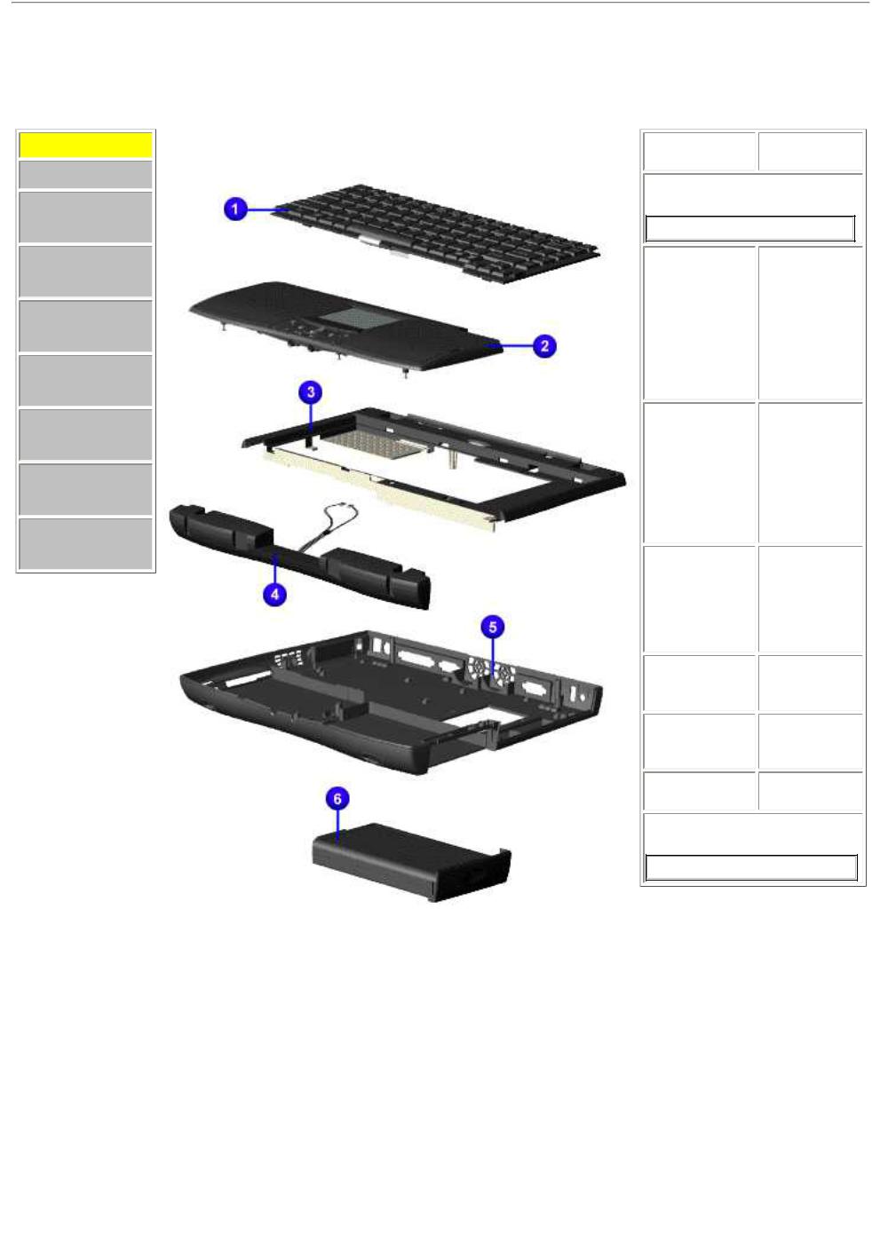
Maintenance & Service Guide
Presario Series
Models: 1246, 1247, 1277, 1278, and 1279
| Home Page | Notice | Preface | Product Description | Troubleshooting Illustrated Parts Catalog | Removal & Replacement Procedures | Specifications Pin Assignments | Battery Pack Operations
Illustrated Parts Catalog
System Unit
System Unit
Boards
Display
Assembly
Mass Storage
Devices
Miscellaneous
Cable Kit
Miscellaneous
Hardware Kit
Miscellaneous
Plastics Kit
Miscellaneous
Parts
Documentation
and Software
Description |
|
Spare Part |
|
Number |
|
|
|
|
1. Keyboard |
|
|
United States 141706-001
Palmrest
Cover
w/TouchPad
and 142654-
Button Board 001 (Models 1277
and 1278)
2. Palmrest Cover w/TouchPad
and Button 142653-001 Board
(Models: 1246, 1247, 1278)
2. Palmrest Cover
w/TouchPad 161416-001 (without Soft
Paint) (Model TBD)
3. Upper CPU
Cover w/Power 158799-001 Switch
4. Speaker
Assembly 148108-001 w/Cables
5. Base 158798-001 Enclosure
6. Battery Pack
LION Enhanced 388647-001
 Loading...