


 Loading...
User’s Reference
Publication number 16555-97015
February 1999
For Safety information, Warranties, and Regulatory information, see the pages behind the Index.
©Copyright Hewlett-Packard Company 1992–1999 All Rights Reserved
HP 16554A, HP 16555A, and
HP 16555D State/Timing
Logic Analyzer

ii
 16554A, 16555A, 16555D User Manual")
In This Book
The User’s Reference manual contains field and feature definitions. Use this manual to learn what the menu fields do, what they are used for, and how the features work.
The manual is divided into chapters covering general product information, probing, and separately tabbed chapters for each analyzer menu. Chapters on error messages and instrument specifications are also provided.
In the Configuration menu you have the choice of configuring an analyzer as either a State analyzer or a Timing analyzer. Some menus in the analyzer will change depending on the analyzer type you choose. For example, because a Timing analyzer does not use external clocks, the clock assignment fields in the Format menu will not be available.
If a menu field is only available to a particular analyzer type, the field is designated (Timing only) or (State only) after the field name. If no designation is shown, the field is available for both types.
1 General Information
2 Probing
3 The Configuration Menu
4 The Format Menu
5 The Trigger Menu
6 The Listing Menu
7 The Waveform Menu
8 The Chart Menu
9 The Compare Menu
10 The Mixed Display Menu
11 The SPA Menu
12 Error Messages
13 Specifications and
Characteristics
14 Installation
Index
iii

iv
Contents
1 General Information
User Interface 1–3 |
|
|
Configuration Capabilities 1–4 |
|
|
Key Features of the HP 16554A |
1–5 |
|
Key Features for the HP 16555A |
1–6 |
|
Key Features for the HP 16555D |
1–7 |
|
Accessories Supplied |
1–8 |
|
Accessories Available |
1–9 |
|
2 Probing
General-Purpose Probing System Description 2–17
Assembling the Probing System 2–21
Connecting the External Reference Clock 2-25
3 The Configuration Menu
Analyzer Name Field |
3–3 |
Analyzer Type Field |
3–4 |
Pod Fields 3–6 |
|
Activity Indicators |
3–8 |
4 The Format Menu
State Acquisition Mode Field (State, State Compare, and SPA only) 4–3 Timing Acquisition Mode Field (Timing only) 4–5
Data on Clocks Display 4–6 Pod Field 4–7
Pod Clock Field (State only) 4–8 Pod Threshold Field 4–12
Master and Slave Clock Fields (State modes only) 4–13 Setup/Hold Field (State only) 4–15
Symbols Field 4–17
Label Assignment Fields 4–17
Contents–1

Contents
Rolling Labels and Pods 4–17
Label Polarity Fields |
4–18 |
Bit Assignment Fields |
4–19 |
5The Trigger Menu
Predefined Trigger Macros 5–3
Timing Trigger Macro Library 5–5 State Trigger Macro Library 5–7
Sequence Levels |
5–9 |
|
||
Sequence Level Number Field 5–10 |
||||
Sequence Instruction Menu |
5–11 |
|||
Resource Terms |
5–17 |
|
||
Resource Term Fields |
5–18 |
|
||
Bit Pattern Terms |
5–21 |
|
||
Range Terms |
5–23 |
|
|
|
Timer Terms 5–25 |
|
|
|
|
Edge Terms (Timing only) |
5–27 |
|||
Combination of Terms |
5–29 |
|
||
Control Fields |
5–31 |
|
|
|
Arming Control Field |
5–32 |
|
||
Count Field (State and State Compare only) 5–35 Acquisition Control Field 5–37
Clear Trigger Field 5–42
Contents–2

Contents
6The Listing Menu
Markers Field 6–3
Pattern Markers 6–4
Find X-pattern / O-pattern Field 6–5
Pattern Occurrence Fields 6–6
From Trigger / Start / X Marker Field 6–7
Specify Patterns Field |
6–8 |
Label / Base Roll Field |
6–11 |
Stop Measurement Field |
6–12 |
Clear Pattern Field 6–14
Time Markers 6–15
Trig to X / Trig to O Fields 6–16
Statistics Markers 6–17
Data Roll Field 6–19
7The Waveform Menu
Basic Controls 7–3
Acquisition Control Field 7–4
Accumulate Field 7–5
States Per Division Field (State and State Compare only) 7–6 Seconds Per Division Field (Timing only) 7–7
Delay Field |
7–8 |
Sample Period Display (Timing only) 7–9 |
|
Markers Field |
7–11 |
Pattern Markers 7–12
X-pat / O-pat Occurrence Fields 7–13
From Trigger / Start / X Marker Field 7–14
Center Screen Field |
7–15 |
Specify Patterns Field |
7–16 |
Contents–3

Contents
Time Markers |
7–17 |
|
|
|||
Trig to X / Trig to O Fields |
7–18 |
|
||||
Marker Label / Base and Display |
7–19 |
|||||
Statistics Markers |
7–20 |
|
|
|||
Waveform Display |
7–22 |
|
|
|||
Display Location Reference Line |
7–23 |
|||||
Blue Bar Field |
7–24 |
|
|
|
||
Channel Mode Field |
7–26 |
|
|
|||
Module and Label Fields 7–27 |
|
|||||
Action Insert/Replace Field |
7–28 |
|
||||
Delete and Delete All Fields |
7–29 |
|||||
Waveform Size Field |
7–30 |
|
|
|||
8 The Chart Menu |
|
|
|
|||
The Y Markers |
8–4 |
|
|
|
||
The X Markers and the Markers Field 8–5 |
||||||
Sample |
8–5 |
|
|
|
|
|
Pattern |
8–6 |
|
|
|
|
|
Rescale |
8–13 |
|
|
|
|
|
Axis Control Field |
8–15 |
|
|
|||
Accumulate Field |
8–18 |
|
|
|||
Cancel Field 8–18 |
|
|
|
|
||
Contents–4

Contents
9The Compare Menu
Reference Listing Field 9–4
Difference Listing Field |
9–5 |
|
|
Copy Listing to Reference Field |
9–7 |
||
Find Error Field |
9–8 |
|
|
Compare Full / Compare Partial Field 9–9 |
|||
Mask Field 9–10 |
|
|
|
Specify Stop Measurement Field |
9–11 |
||
Data Roll Field |
9–14 |
|
|
Bit Editing Field |
9–15 |
|
|
Label and Base Fields |
9–16 |
|
|
Label / Base Roll Field |
9–16 |
|
|
10The Mixed Display Menu
Intermodule Configuration 10–3
Inserting Waveforms 10–4 |
|
Interleaving State Listings |
10–4 |
Time-Correlated Displays |
10–5 |
Markers 10–5 |
|
11 The SPA Menu
System Performance Analysis Software 11–2
What is System Performance Analysis? 11–4
Getting Started 11–6 |
|
SPA Measurement Processes |
11–8 |
Using State Overview, State Histogram, and Time Interval 11–21 |
|
Using SPA with other features |
11–30 |
12 Error Messages
Error Messages 12–3
Warning Messages 12–4
Advisory Messages 12–7
Contents–5

Contents
13 Specifications and Characteristics
Specifications 13–3
Supplemental Characteristics 13–4
14 Installation
To configure a single-card module |
14–2 |
||
To configure a multi-card module |
14–3 |
||
To install modules |
14–8 |
|
|
Preparing for Use |
14-9 |
|
|
Inspecting the module |
14-10 |
|
|
Cleaning the module |
14-10 |
|
|
Index
Contents–6
1
General Information

Logic Analyzer Description
The HP 16554A, 16555A, and 16555D State/Timing Analyzer modules are part of a new generation of general-purpose logic analyzers. They are used with the HP 16500 Logic Analysis System mainframe, which is designed as a standalone instrument for use by digital and microprocessor hardware and software designers. The HP 16500 mainframe has HP-IB and RS-232-C interfaces for hard copy printouts and control by a host computer.
Both State/Timing Analyzer modules have 64 data channels, and four clock/data channels. As many as two additional HP 16554A, 16555A, or 16555D cards can be added to expand the module to 200 data and
4 clock/data channels.
Memory depth on the HP 16554A is 500K in all pod pair groupings, or 1M on just one pod (timing half-channel mode). Memory depth on the HP 16555A is 1M in all pod pair groupings, or 2M on just one pod (timing half-channel mode). Memory depth on the HP 16555D is 2M in all pod pair groupings, or 4M on just one pod (timing half-channel mode). All available resource terms can be assigned to either configured state or timing analyzer machine.
Measurement data is displayed as data listings or waveforms.
The 70-MHz and 110-MHz state analyzers have master, slave, and demultiplexed clocking modes available. Measurement data can be stamped with either state or time tags. For triggering and data storage, the state analyzer uses 12 sequence levels with two-way branching, 10 pattern resource terms, 2 range terms, and 2 timers/counters.
The 250-MHz and 500-MHz conventional timing analyzers have variable width, depth, and speed selections. Sequential triggering uses 10 sequence levels with two-way branching, 10 pattern resource terms, 2 range terms, 2 timers/counters and 2 edge/glitch terms.
1–2

General Information
User Interface
User Interface
The HP 16500 Logic Analysis System has four easy-to-use user interface devices: the knob, the touchscreen, the mouse, and the optional keyboard.
The knob on the front panel is used to move the cursor on certain menus, to increment or decrement numeric fields, and to roll the display.
The touchscreen fields can be selected by touch or with the mouse or keyboard. To activate a touchscreen field by touch, simply press the screen over any dark blue box on the display with your finger until the field changes color. Then remove your finger from the screen to activate your selection.
To activate a field with the mouse, position the cursor (+) of the mouse over the desired field and press the button on the upper-left corner of the mouse.
The optional keyboard can control all instrument functions by using special function keys, the arrow keys, and the ENTER key. Alphanumeric entry is simply typed in.
All user interface devices are discussed in more detail in the HP 16500 User’s Reference.
1–3

General Information
Configuration Capabilities
|
Configuration Capabilities |
|
The HP 16554A, 16555A, and 16555D can be configured as a single card, |
|
two-card, or three-card system. The number of data channels ranges from 68 |
|
channels using just one card to 204 channels when three cards are installed. |
|
A half-channel acquisition mode is available for timing analyzers which |
|
reduces the channel width by half, but doubles memory depth from |
|
500K-deep to 1M-deep per channel on the HP 16554A, from 1M-deep to |
|
2M-deep per channel on the HP 16555A and from 2M-deep to 4M-deep per |
|
channel on the HP 16555D. |
|
Modules are made of cards cabled together to form a single timebase. A logic |
|
analyzer module may use from one to three cards. All the cards in a module |
|
must have the same model number. Because the clock is common to all |
|
cards in a module, the data is always synchronized. For tightly coupled |
|
measurements involving multiple HP 16554A, 16555A, or 16555D modules, |
|
your analyzer module provides an external reference clock. The reference |
|
clock prevents large data samples from becoming unsynchronized towards |
|
the end of a measurement. Because the internal clock on each logic analyzer |
|
card is accurate to 100 parts per million, in a 2M timing measurement using |
|
two modules, the last sample of each may be separated by as much as 100 |
|
times the sample period. The external reference clock prevents this by |
|
having multiple modules share the same clock. There is no limit to how many |
|
modules may share the clock. |
See Also |
"Connecting the External Reference Clock" in chapter 2, Probing, for |
|
information on configuring the external reference clock. |
1–4

General Information
Key Features of the HP 16554A
Key Features of the HP 16554A
∙70-MHz state and 250-MHz timing acquisition speed.
∙64 data channels/4 clocks expandable to 200 data/4 clock channels.
∙Lightweight passive probes for easy hookup and compatibility with previous HP logic analyzers and preprocessors.
∙HP-IB and RS-232-C interface for programming and hard copy printouts.
∙Variable setup/hold time, 3.5-ns window.
∙External arming to and from other modules through the intermodule bus.
∙500-K deep memory on all channels with 1 Mbyte in half-channel modes.
∙Marker measurements.
∙12 levels of trigger sequencing for state and 10 levels of sequential triggering for Timing.
∙Both state and timing analyzers can use 10 pattern resource terms, two range terms, and two timer/counters to qualify and trigger on data. The timing analyzer also has two edge terms available.
∙Time (8-ns resolution) and number-of-qualified-states tagging.
∙Full programmability.
∙Mixed State/Timing and State/State (interleaved) display.
∙Waveform display.
1–5

General Information
Key Features for the HP 16555A
Key Features for the HP 16555A
∙110-MHz state and 500-MHz timing acquisition speed.
∙64 data channels/4 clocks expandable to 200 data/4 clock channels.
∙Lightweight passive probes for easy hookup and compatibility with previous HP logic analyzers and preprocessors.
∙HP-IB and RS-232-C interface for programming and hard copy printouts.
∙Variable setup/hold time, 3.5-ns window.
∙External arming to and from other modules through the intermodule bus.
∙1-M deep memory on all channels with 2 Mbytes in half-channel modes.
∙Marker measurements.
∙12 levels of trigger sequencing for state and 10 levels of sequential triggering for Timing.
∙Both state and timing analyzers can use 10 pattern resource terms, two range terms, and two timer/counters to qualify and trigger on data. The timing analyzer also has two edge terms available.
∙Time (8-ns resolution) and number-of-qualified-states tagging.
∙Full programmability.
∙Mixed State/Timing and State/State (interleaved) display.
∙Waveform display.
1–6

General Information
Key Features for the HP 16555D
Key Features for the HP 16555D
∙110-MHz state and 500-MHz timing acquisition speed.
∙64 data channels/4 clocks expandable to 200 data/4 clock channels.
∙Lightweight passive probes for easy hookup and compatibility with previous HP logic analyzers and preprocessors.
∙HP-IB and RS-232-C interface for programming and hard copy printouts.
∙Variable setup/hold time, 3.5-ns window.
∙External arming to and from other modules through the intermodule bus.
∙2-M deep memory on all channels with 4 Mbytes in half-channel modes.
∙Marker measurements.
∙12 levels of trigger sequencing for state and 10 levels of sequential triggering for Timing.
∙Both state and timing analyzers can use 10 pattern resource terms, two range terms, and two timer/counters to qualify and trigger on data. The timing analyzer also has two edge terms available.
∙Time (8-ns resolution) and number-of-qualified-states tagging.
∙Full programmability.
∙Mixed State/Timing and State/State (interleaved) display.
∙Waveform display.
1–7

General Information
Accessories Supplied
Accessories Supplied
The table below lists the accessories supplied with your logic analyzer. If any of these accessories are missing, contact your nearest Hewlett-Packard Sales Office. If you need additional accessories, refer to the Accessories for
HP Logic Analyzers brochure.
Table 1-1 |
Accessories Supplied |
|
|
|
|
|
|
|
Accessory |
HP Part No. |
Quantity |
|
Probe tip assemblies |
01650-61608 |
4 |
|
Probe cables |
16555-61608 |
2 |
|
Grabbers (20 per pack) |
5090-4356 |
4 pkgs |
|
Extra probe leads (5 per pack) |
5959-9333 |
1 pkg |
|
Probe cable and pod labels |
01650-94310 |
1 |
|
Double probe adapter |
16542-61607 |
1 |
|
External reference cable |
16555-61608 |
1 |
|
Ferrite instructions |
16555-92000 |
1 |
|
Ferrite cores |
16555-60001 |
2 |
|
Probe grounds (5 per pack) |
5959-9334 |
4 |
|
Operating system disks |
Call |
1 |
|
User’s Reference |
Call |
1 |
1–8

General Information
Accessories Available
Accessories Available
There are a number of accessories available that will make your measurement tasks easier and more accurate. You will find these listed in Accessories for HP Logic Analyzers, available from your Hewlett-Packard Sales Office.
Preprocessor Modules
The preprocessor module accessories enable you to quickly and easily connect the logic analyzer to your microprocessor under test.
Included with each preprocessor module is a 3.5-inch disk which contains a configuration file and an inverse assembler file. When you load the configuration file, it configures the logic analyzer for making state measurements on the microprocessor for which the preprocessor is designed.
Configuration files from other analyzer modules can also be loaded. For information on translating other configuration files into the analyzer, refer to "Preprocessor File Configuration Translation and Pod Connections" in chapter 2, "Probing".
The inverse assembler file is a software routine that will display captured information in a specific microprocessor’s mnemonics. The DATA field in the State Listing is replaced with an inverse assembly field. The inverse assembler software is designed to provide a display that closely resembles the original assembly language listing of the microprocessor’s software. It also identifies the microprocessor bus cycles captured, such as Memory Read, Interrupt Acknowledge, or I/O write.
Many of the preprocessor modules require the HP10269C General Purpose Probe Interface. The HP 10269C accepts the specific preprocessor PC board and connects it to five connectors on the general purpose interface to which the logic analyzer probe cables connect.
A list of preprocessor modules is found in the Accessories for HP Logic Analyzers brochure. Descriptions of the preprocessor modules are found with the preprocessor module accessories.
1–9

1–10
2
Probing

Probing
This chapter contains a description of the probing system for the logic analyzer. It also contains the information you need for connecting the probe system components to each other, to the logic analyzer, and to the system under test.
Probing Options
You can connect the logic analyzer to your system under test in one of the following ways:
∙The standard general purpose probing (provided).
∙HP E2445A User-Definable Interface (optional).
∙Direct connection to a 20-pin, 3M-Series type header connector using the termination adapter (optional).
∙Microprocessor and bus specific interfaces (optional).
General-Purpose Probing
General-purpose probing involves connecting the logic analyzer probes directly to your target system without using any interface. General purpose probing does not limit you to specific hook up schemes, as for example, the probe interface does. General-purpose probing uses grabbers that connect to both through hole and surface mount components.
General-purpose probing is the standard probing option provided with the logic analyzer. There is a full description of its components and use later in this chapter.
2–2
Probing
The HP E2445A User-Definable Interface
The optional HP E2445A User-Definable Interface allows you to connect the logic analyzer to the microprocessor in your target system. The HP E2445A includes a breadboard that you custom-wire for your system.
You will find additional information about the HP E2445A in the
Accessories for HP Logic Analyzers brochure.
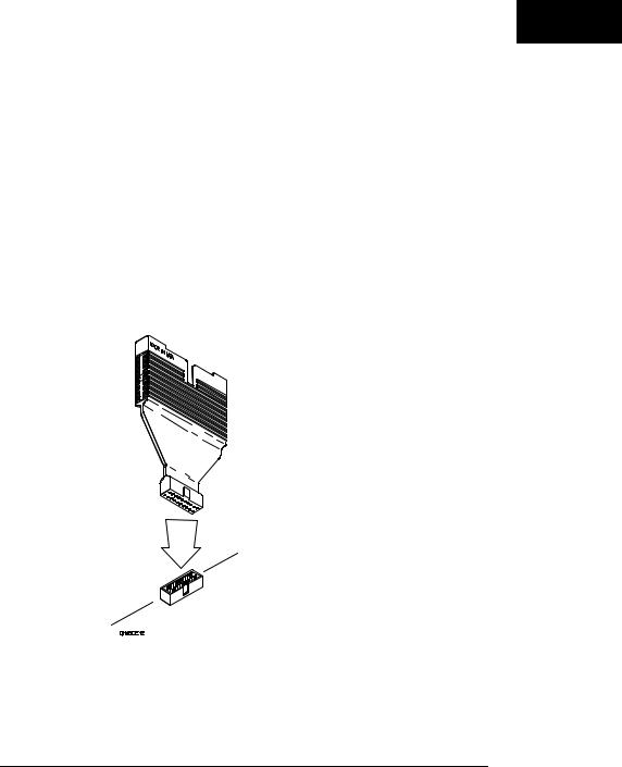
The Termination Adapter
The optional termination adapter allows you to connect the logic analyzer probe cables directly to test ports on your target system without the probes.
The termination adapter is designed to connect to a 20-pin (2x10), 4-wall, low-profile header connector, 3M-Series 3592 or equivalent.
Termination Adapter
2–3

Probing
Microprocessor and Bus-Specific Interfaces
There are a number of microprocessor and bus-specific interfaces available as optional accessories which are listed in Microprocessor and Bus Interfaces and Software Accessories for HP Logic Analyzers. Microprocessors are supported by Universal Interfaces or Preprocessor Interfaces, or in some cases both.
Preprocessor interfaces are aimed at hardware turn-on and hardware/software integration, and will provide the following:
∙All clocking and demultiplexing circuits needed to capture the system’s operation.
∙Additional status lines to further decode the operation of the CPU.
∙Inverse assembly software to translate logic levels captured by the logic analyzer into microprocessor mnemonics.
∙Bus interfaces to support bus analysis for HP-IB, RS-232-C, RS-449, SCSI, VME, VXI, ISA, EISA, MCA, FDDI, Futurebus+, JTAG, SBus, PCI, and PCMCIA.
Universal Interfaces are aimed at initial hardware turn-on, and will provide fast, reliable, and convenient connections to the microprocessor system. Universal Interfaces do not provide inverse assembly of software instructions.
2–4

Probing
Preprocessor File Configuration Translation and Pod Connections
Preprocessor configuration files from an HP 16550A can be used by the HP16554A, 16555A, and 16555D logic analyzers. However, some pods must be connected differently in order for the configuration files to work properly. The tables on the next several pages provide information on what configuration files to load and the required connections between the preprocessor interface and the HP 16554A, 16555A, and 16555D pods.
In the tables, expansion and master card pods are referred to as either A or B pods. Those designations are done for convenience. The letter designation of pods in your system will depend on the slots in which your cards reside. They may use any letter from A through E for the 16500 Logic Analysis System mainframe, or F through J for the 16501A Expander Frame
In a five-card system, for example, the master card pods would be labeled C. The expansion card pods then would be labeled A, B, D, and E. Look at the Format menu for the slot designators for expansion cards in your system.
The following three tables provide configuration file names and pod connections for older microprocessors. Look in the microprocessorspecific preprocessor manual for configuration and connection information for newer microprocessors.
2–5

Probing
Software and Hardware Translation Information
Table 2-1
Single-card HP16550A configuration loaded into single-card HP16554 or HP 16555A or HP 16555D
|
|
|
Master Card |
|
|
|||
|
|
16550A Config |
Pods |
|
|
|
|
|
HP Model |
Processor |
Filename |
B4 B3 B2 B1 |
Clocks |
Drop Pods |
|||
10300B |
Z80 |
FZ80 |
-- |
P2 |
-- |
P1 |
J+L |
No |
Inverse Assembler Labels: P1=DATA/STAT.clk |
|
|
|
|
|
|
||
P2=ADDR.clk |
|
|
|
|
|
|
|
|
10304B |
8085 |
C8085_IF |
-- |
P3 |
P2 |
P1 |
J, K |
No |
|
|
|
|
|
|
|
mclk, sclk |
|
Inverse Assembler Labels: P1=DATA/STAT.master_clk |
|
|
|
|
|
|
||
P2=ADDR.slave_clk |
|
|
|
|
|
|
|
|
10305B |
8086 |
F8086_I |
P3 |
P2 |
-- |
P1 |
J |
No |
Inverse Assembler Labels: P1=DATA.clk P2=ADDR P3=ADDR/STAT |
|
|
|
|
||||
10305B |
8088 |
F8088_I |
P3 |
P2 |
-- |
P1 |
J |
No |
Inverse Assembler Labels: P1=DATA.clk P2=ADDR P3=ADDR/STAT |
|
|
|
|
||||
10315G/H |
68HC11 |
F68HC11 |
-- |
P2 |
-- |
P1 |
L, J |
Timing |
|
|
|
|
|
|
|
mclk, sclk |
P3, P4 |
Inverse Assembler Labels: P1=ADDR/DATA.slave_clk P2=ADDR/STAT.master_clk |
|
|
||||||
10341B |
1553 |
F1553 |
-- |
P2 |
-- |
P1 |
J |
Timing |
Inverse Assembler Labels: P1=DATA.clk (no Inverse Assembler capability) |
|
P3 |
||||||
10342B |
RS232 |
FRS232 |
-- |
P3 |
P4 |
P1 |
K |
No |
Inverse Assembler Labels: P1=DATA/STAT P4=.clk |
|
|
|
|
|
|
||
10342B |
HPIB |
FHPIB |
. |
|
P3 |
P2 |
J |
No |
Inverse Assembler Labels: P2=DATA/STAT.clk P3=DATA |
|
|
|
|
|
|
||
2–6

Probing
Table 2-1 (continued)
Single-card HP16550A configuration loaded into single-card HP16554 or HP 16555A or HP 16555D
|
|
|
Master Card |
|
|
|||
|
|
16550A Config |
Pods |
|
|
|
|
|
HP Model |
Processor |
Filename |
B4 B3 B2 B1 |
Clocks |
Drop Pods |
|||
10342G |
HPIB |
FHPIB |
-- J2 |
-- J2 |
J |
No |
||
Inverse Assembler Labels: J2=DATA/STAT.clk |
|
|
|
|
|
|
||
E2409B |
80286 |
F80286S |
P3 |
P2 |
-- |
P1 |
J |
Timing |
Inverse Assembler Labels: P1=Data.clk P2=ADDR P3=ADDR/STAT |
|
|
|
P4, P5 |
||||
E2409B |
80286 |
F80286T |
P3 |
P2 |
-- |
P4 |
Timing |
Timing |
Inverse Assembler Labels: n/a |
|
|
|
|
|
|
P5 |
|
E2413B |
68331/2 |
F68332 |
P4 |
P3 |
P5 |
P1 |
J |
State |
Inverse Assembler Labels: P1=DATA.clk P3=ADDR P4=ADDR |
P5=STAT |
|
|
P2, P6 |
||||
E2414B |
68302 |
F68302 |
-- |
P4 |
P3 |
P1 |
J |
No |
Inverse Assembler Labels: P1=DATA.clk P3=ADDR P4=ADDR/STAT |
|
|
|
|
||||
E2415A |
MCS-51 |
FMCS51 |
-- |
P2 |
P3 |
P1 |
J |
State |
Inverse Assembler Labels: P1=DATA.clk P2=ADDR P3=STAT |
|
|
|
|
|
P5 |
||
E2416A |
MCS-96 |
FMCS96 |
-- |
P3 |
P2 |
P1 |
J |
No |
Inverse Assembler Labels: P1=DATA.clk P2=ADDR |
|
|
|
|
|
|
||
P3=STAT |
|
|
|
|
|
|
|
|
E2418A |
320C20/25 |
F320C25 |
J3 |
J1 |
-- |
J2 |
J |
No |
Inverse Assembler Labels: J1=DATA J2=ADDR.clk J3=STAT |
|
|
|
|
|
|
||
E2419A |
68HC16 |
FHC16 |
P4 |
P3 |
P5 |
P1 |
J |
State |
Inverse Assembler Labels: P1=DATA.clk P3=ADDR P5=STAT (P4=ADDR not required) |
P2, P6 |
|||||||
2–7

Probing
Table 2-1 (continued)
Single-card HP16550A configuration loaded into single-card HP16554 or HP 16555A or HP 16555D
|
|
|
Master Card |
|
|
|||
|
|
16550A Config |
Pods |
|
|
|
|
|
HP Model |
Processor |
Filename |
B4 B3 B2 B1 |
Clocks |
Drop Pods |
|||
E2423A |
SCSI-2 |
FSCSI2 |
P4 |
P3 |
P2 |
P1 |
J |
No |
Inverse Assembler Labels: P1=STAT.clk P2=ADDR/DATA |
|
|
|
|
|
|
||
E2424B |
68340 |
F68340 |
P4 |
P3 |
P5 |
P1 |
K |
No |
Inverse Assembler Labels: P1=DATA P3=ADDR P5=STAT.clk (P4=ADDR_B not required) |
|
|||||||
E2424B |
68340 |
FEV340 |
P4 |
P3 |
P5 |
P1 |
J |
No |
Inverse Assembler Labels: P1=DATA.clk P3=ADDR P5=STAT (P4=ADDR not |
|
|
||||||
required) |
|
|
|
|
|
|
|
|
E2431A |
320C30/31 |
P_320C3X |
P4 |
P3 |
P2 |
P1 |
J↕ |
No |
Inverse Assembler Labels: P1=DATA.clk P2=DATA P3=ADDR |
|
|
|
|
|
|
||
P4=ADDR/STAT |
|
|
|
|
|
|
|
|
E2431A |
320C30/31 |
Q_320C30 |
P6 |
P5 |
-- |
P7 |
J↕ |
No |
Inverse Assembler Labels: P5=DATA P6=DATA P7=ADDR/STAT.clk
Note: A single-card HP 16555A is not recommended for this preprocessor because it does not allow simultaneous viewing of both the primary and expansion microprocessor buses.
E2434A |
80186XL/88 |
C186EA09 |
P4 |
P3 |
-- |
P1 |
J |
No |
Inverse Assembler Labels: P1=DATA.clk P3=ADDR P4=ADDR/STAT |
|
|
|
|
||||
E2434A |
80186XL/88 |
C186EA10 |
P6 |
P5 |
P4 |
P2 |
Timing |
No |
Inverse Assembler Labels: n/a |
|
|
|
|
|
|
|
|
E2434B |
80186/88EB |
C186EB_7 |
P4 |
P3 |
-- |
P1 |
J |
No |
Inverse Assembler Labels: P1=DATA.clk P3=ADDR P4=ADDR/STAT |
|
|
|
|
||||
E2434B |
80186/88EB |
C186EB_8 |
P6 |
P5 |
P4 |
P2 |
Timing |
Timing |
Inverse Assembler Labels: n/a |
|
|
|
|
|
|
P7 |
|
2–8

Probing
Table 2-1 (continued)
Single-card HP16550A configuration loaded into single-card HP16554 or HP 16555A or HP 16555D
|
|
|
Master Card |
|
|
|
|||
|
|
16550A Config |
Pods |
|
|
|
|
|
|
HP Model |
Processor |
Filename |
B4 B3 B2 B1 |
Clocks |
|
Drop Pods |
|||
E2434C |
80186/88EC |
C186EC_7 |
P4 |
P3 |
P6 |
P1 |
J |
|
No |
Inverse Assembler Labels: P1=DATA.clk P3=ADDR P4=ADDR/STAT |
|
|
|
|
|
||||
E2434C |
80186/88EC |
C186EC_8 |
P5 |
P6 |
P7 |
P2 |
Timing |
|
Timing |
Inverse Assembler Labels: n/a |
|
|
|
|
|
|
|
P8 |
|
E2442A |
TMS320C5X |
D_320C5X |
P5 |
P2 |
P3 |
P1 |
J+K+L |
|
State |
Inverse Assembler Labels: P1=DATA.clk P2=STAT.clk P3=ADDR.clk |
|
|
|
|
P4, P6 |
||||
E2447AA |
68000 |
F68000 |
P6 |
P1 |
P4 |
P3 |
K |
|
No |
Inverse Assembler Labels: P1=DATA P3=ADDR P4=ADDR/STAT.clk |
|
|
|
|
|
||||
E2447AA |
68010 |
F68010 |
P6 |
P1 |
P4 |
P3 |
K |
|
No |
Inverse Assembler Labels: P1=DATA P3=ADDR P4=ADDR/STAT.clk |
|
|
|
|
|
||||
E2447AB |
68EC000 |
FEC000 |
P6 |
P1 |
P4 |
P3 |
K |
|
No |
Inverse Assembler Labels: P1=DATA P3=ADDR P4=ADDR/STAT.clk |
|
|
|
|
|
||||
E2451A |
Ethernet |
CETH_4 |
P4 |
P3 |
P2 |
P1 |
J |
|
No |
Inverse Assembler Labels: P1=DATA.clk P2=ADDR/DATA_B P3=ADDR/DATA_B P4=STAT |
|
|
|||||||
E2453A |
DS1 |
C_DS1_6 |
. |
|
-- |
xx |
J↕ |
|
No |
Inverse Assembler Labels: Carrier/Customer=ADDR/DATA/STAT.clk |
|
|
|
|
|
||||
E2453A |
DS1 |
C_DS1_7 |
-- |
Cu |
-- |
Ca |
J↕ |
L↕ |
No |
|
|
|
mach2 mach1 |
mach1 mach2 |
|
||||
Inverse Assembler Labels: Carrier=ADDR/DATA/STAT.clk Customer=ADDR/DATA/STAT.clk |
|
|
|||||||
2–9

Probing
Table 2-2
Single-card HP16550A configuration loaded into multi-card HP16554 or HP 16555A or HP 16555D
|
|
16550A |
Expansion |
Master Card |
|
|
||||
|
|
Config |
Card Pods |
Pods |
|
|
|
|
||
HP Model |
Processor |
Filename |
A4 A3 A2 A1 |
B4 B3 B2 B1 |
Clocks |
Drop Pods |
||||
10300B |
Z80 |
FZ80 |
|
|
-- |
P2 |
-- |
P1 |
J+L |
No |
Inverse Assembler Labels: P1=DATA/STAT.clk P2=ADDR.clk |
|
|
|
|
|
|
||||
10304B |
8085 |
C8085_IF |
. |
-- P3 |
. |
|
P2 |
P1 |
J, K |
No |
|
|
|
|
|
|
|
|
|
mclk, sclk |
|
Inverse Assembler Labels: P1=DATA/STAT.master_clk P2=ADDR.slave_clk |
|
|
|
|
||||||
10305B |
8086 |
F8086_I |
. |
P3 P2 |
. |
|
-- |
P1 |
J |
No |
Inverse Assembler Labels: P1=DATA.clk P2=ADDR P3=ADDR/STAT |
|
|
|
|
|
|
||||
10305B |
8088 |
F8088_I |
. |
P3 P2 |
. |
|
-- |
P1 |
J |
No |
Inverse Assembler Labels: P1=DATA.clk P2=ADDR P3=ADDR/STAT |
|
|
|
|
|
|
||||
10315G/H |
68HC11 |
F68HC11 |
|
|
-- |
P2 |
-- |
P1 |
L, J |
Timing |
|
|
|
|
|
|
|
|
|
mclk, sclk |
P3, P4 |
Inverse Assembler Labels: P1=ADDR/DATA.slave_clk P2=ADDR/STAT.master_clk |
|
|
||||||||
10341B |
1553 |
F1553 |
. |
-- P2 |
-- |
P3 |
-- |
P1 |
J |
No |
Inverse Assembler Labels: P1=DATA.clk (no Inverse Assembler capability) |
|
|
|
|
||||||
10342B |
RS232 |
FRS232 |
|
|
-- |
P3 |
P4 |
P1 |
K |
No |
Inverse Assembler Labels: P1=DATA/STAT P4=.clk |
|
|
|
|
|
|
|
|||
10342B |
HPIB |
FHPIB |
|
|
. |
|
P3 |
P2 |
J |
No |
Inverse Assembler Labels: P2=DATA/STAT.clk P3=DATA |
|
|
|
|
|
|
|
|||
10342G |
HPIB |
FHPIB |
|
|
-- |
J2 |
--- |
J2 |
J |
No |
Inverse Assembler Labels: J2=DATA/STAT.clk |
|
|
|
|
|
|
|
|
||
2–10
Loading...