


 Loading...
HP 15 Notebook PC
Maintenance and Service Guide
© Copyright 2015 HP Development Company,
L.P.
AMD is a trademark of Advanced Micro Devices, Inc. Bluetooth is a trademark owned by its proprietor and used by HP Inc. under license. Intel, Celeron, Centrino, and Pentium are trademarks of Intel Corporation in the U.S. and other countries. Microsoft and Windows are U.S. registered trademarks of the Microsoft group of companies.
The information contained herein is subject to change without notice. The only warranties for HP products and services are set forth in the express warranty statements accompanying such products and services. Nothing herein should be construed as constituting an additional warranty. HP shall not be liable for technical or editorial errors or omissions contained herein.
Second Edition: August 2015
First Edition: November 2014
Document Part Number: 793965-002
Product notice
This guide describes features that are common to most models. Some features may not be available on your computer.
Not all features are available in all editions of Windows. This computer may require upgraded and/or separately purchased hardware, drivers, and/or software to take full advantage of Windows functionality. See http://www.microsoft.com for details.
Software terms
By installing, copying, downloading, or otherwise using any software product preinstalled on this computer, you agree to be bound by the terms of the HP End User License Agreement (EULA). If you do not accept these license terms, your sole remedy is to return the entire unused product (hardware and software) within 14 days for a refund subject to the refund policy of your place of purchase.
For any further information or to request a full refund of the computer, please contact your local point of sale (the seller).

Important Notice about Customer Self-Repair Parts
 CAUTION: Your computer includes Customer Self-Repair parts and parts that should only be accessed by an authorized service provider. See Chapter 5, "Removal and replacement procedures for Customer Self-Repair parts," for details. Accessing parts described in Chapter 6, "Removal and replacement procedures for Authorized Service Provider only parts," can damage the computer or void your warranty.
iii
iv Important Notice about Customer Self-Repair Parts

Safety warning notice
 WARNING! To reduce the possibility of heat-related injuries or of overheating the device, do not place the device directly on your lap or obstruct the device air vents. Use the device only on a hard, at surface. Do not allow another hard surface, such as an adjoining optional printer, or a soft surface, such as pillows or rugs or clothing, to block air ow. Also, do not allow the AC adapter to contact the skin or a soft surface, such as pillows or rugs or clothing, during operation. The device and the AC adapter comply with the user-accessible surface temperature limits de ned by the International Standard for Safety of Information Technology Equipment (IEC 60950).
v
vi Safety warning notice

Table of contents
1 Product description ....................................................................................................................................... |
1 |
2 External component identi c tion .................................................................................................................. |
4 |
Right side ............................................................................................................................................................... |
4 |
Left side ................................................................................................................................................................. |
5 |
Display .................................................................................................................................................................... |
6 |
Top .......................................................................................................................................................................... |
8 |
TouchPad ............................................................................................................................................. |
8 |
Lights ................................................................................................................................................... |
8 |
Buttons and speakers ....................................................................................................................... |
10 |
Keys ................................................................................................................................................... |
11 |
Bottom ................................................................................................................................................................. |
12 |
Locating system information .............................................................................................................................. |
14 |
3 Illustrated parts catalog .............................................................................................................................. |
15 |
Computer major components .............................................................................................................................. |
15 |
Display assembly subcomponents ...................................................................................................................... |
19 |
Miscellaneous parts ............................................................................................................................................. |
20 |
Mass storage devices ........................................................................................................................................... |
21 |
4 Removal and replacement procedures preliminary requirements .................................................................... |
22 |
Tools required ...................................................................................................................................................... |
22 |
Service considerations ......................................................................................................................................... |
22 |
Plastic parts ....................................................................................................................................... |
22 |
Cables and connectors ...................................................................................................................... |
23 |
Drive handling ................................................................................................................................... |
23 |
Grounding guidelines ........................................................................................................................................... |
24 |
Electrostatic discharge damage ........................................................................................................ |
24 |
Packaging and transporting guidelines .......................................................................... |
25 |
Workstation guidelines ................................................................................................... |
25 |
Equipment guidelines ..................................................................................................... |
26 |
5 Removal and replacement procedures for Customer Self-Repair parts ............................................................. |
27 |
Component replacement procedures .................................................................................................................. |
27 |
Battery ............................................................................................................................................... |
28 |
Service door ....................................................................................................................................... |
29 |
vii
Memory module ................................................................................................................................ |
30 |
WLAN module .................................................................................................................................... |
31 |
Optical drive ....................................................................................................................................... |
33 |
6 Removal and replacement procedures for Authorized Service Provider parts ................................................... |
35 |
Component replacement procedures .................................................................................................................. |
35 |
Display panel ..................................................................................................................................... |
36 |
Keyboard ........................................................................................................................................... |
38 |
Top cover ........................................................................................................................................... |
40 |
Hard drive .......................................................................................................................................... |
44 |
Power button board .......................................................................................................................... |
47 |
TouchPad button board ..................................................................................................................... |
49 |
Optical drive connector cable ............................................................................................................ |
51 |
System board .................................................................................................................................... |
52 |
RTC battery ........................................................................................................................................ |
57 |
Fan ..................................................................................................................................................... |
59 |
Heat sink assembly ........................................................................................................................... |
61 |
Power connector cable ...................................................................................................................... |
63 |
Speakers ............................................................................................................................................ |
64 |
Display assembly ............................................................................................................................... |
65 |
7 Using Setup Utility (BIOS) in Windows 8.1 ...................................................................................................... |
73 |
Starting Setup Utility (BIOS) ................................................................................................................................ |
73 |
Updating the BIOS ................................................................................................................................................ |
73 |
Determining the BIOS version ........................................................................................................... |
73 |
Downloading a BIOS update .............................................................................................................. |
73 |
8 Using Setup Utility (BIOS) in Windows 10 ....................................................................................................... |
75 |
Starting Setup Utility (BIOS) ................................................................................................................................ |
75 |
Updating Setup Utility (BIOS) .............................................................................................................................. |
75 |
Determining the BIOS version ........................................................................................................... |
75 |
Downloading a BIOS update .............................................................................................................. |
76 |
Synchronizing a tablet and keyboard (select products only) .............................................................................. |
77 |
9 Backing up, restoring, and recovering in Windows 8.1 .................................................................................... |
78 |
Creating recovery media and backups ................................................................................................................ |
78 |
Creating HP Recovery media (select models only) ........................................................................... |
78 |
Using Windows tools ........................................................................................................................................... |
79 |
Restore and recovery ........................................................................................................................................... |
79 |
Recovering using HP Recovery Manager ........................................................................................... |
80 |
viii
What you need to know before you get started ............................................................. |
80 |
Using the HP Recovery partition (select models only) ................................................... |
81 |
Using HP Recovery media to recover .............................................................................. |
81 |
Changing the computer boot order ................................................................................ |
81 |
Removing the HP Recovery partition (select models only) ............................................ |
82 |
10 Backing up, restoring, and recovering in Windows 10 .................................................................................... |
83 |
Creating recovery media and backups ................................................................................................................ |
83 |
Creating HP Recovery media (select products only) ......................................................................... |
83 |
Using Windows tools ........................................................................................................................................... |
84 |
Restore and recovery ........................................................................................................................................... |
85 |
Recovering using HP Recovery Manager ........................................................................................... |
85 |
What you need to know before you get started ............................................................. |
85 |
Using the HP Recovery partition (select products only) ................................................. |
86 |
Using HP Recovery media to recover .............................................................................. |
86 |
Changing the computer boot order ................................................................................ |
87 |
Removing the HP Recovery partition (select products only) ......................................... |
87 |
11 Using HP PC Hardware Diagnostics (UEFI) ..................................................................................................... |
88 |
Downloading HP PC Hardware Diagnostics (UEFI) to a USB device .................................................................... |
89 |
12 peci c tions ............................................................................................................................................ |
90 |
Computer speci cations ...................................................................................................................................... |
90 |
15.6-inch display speci cations .......................................................................................................................... |
90 |
Hard drive speci cations ..................................................................................................................................... |
91 |
13 Power cord set requirements ...................................................................................................................... |
92 |
Requirements for all countries ............................................................................................................................ |
92 |
Requirements for speci c countries and regions ................................................................................................ |
92 |
14 Recycling .................................................................................................................................................. |
94 |
Index ............................................................................................................................................................. |
95 |
ix
x
1Product description
Category |
Description |
|
|
|
|
Product Name |
HP 15 Notebook PC |
|
|
|
|
Processors |
Processors are attached to the system board. |
|
|
● |
Intel Core i3-4030U, 1.9 GHz, 1333 MHz/3 MB L2 cache, 15 W |
|
● |
Intel Core i3-4010U, 1.7 GHz, 1333 MHz/3 MB L2 cache, 15 W |
|
● |
Intel Core i3-4005U, 1.7 GHz, 1333 MHz/3 MB L2 cache, 15 W |
|
● |
Intel Pentium N3540, 2.16 GHz, turbo up to 2.66 GHz, 1333 MHz/2 MB L2 cache, 4.5 W |
|
● |
Intel Pentium N3530, 2.16 GHz, turbo up to 2.58 GHz, 1333 MHz/2 MB L2 cache, 4.5 W |
|
● |
Intel Celeron N2940, 1.83 GHz, turbo up to 2.25 GHz, 1333 MHz/2 MB L2 cache, quad SDP, 4.5 W |
|
● |
Intel Celeron N2840, 2.16 GHz, turbo up to 2.25 GHz, 1333 MHz/2 MB L2 cache, 4.5 W |
|
● |
Intel Celeron N2830, 1.83 GHz, turbo up to 2.41 GHz, 1333 MHz/2 MB L2 cache, 4.5 W |
|
|
|
Chipset |
Intel Bay Trail-M SoC |
|
|
Intel Shark Bay ULT One Chip Solution |
|
|
Intel Braswell SoC |
|
|
|
|
Graphics |
Internal graphics: |
|
|
● |
Intel HD Graphics 4400 (Core i3 processors) |
|
● |
Intel HD Graphics (Pentium and Celeron processors) |
|
Supports either HD Decode, DX11.1, and HDMI or HD Decode, DX11, and HDMI |
|
|
|
|
Panel |
15.6 in, white light-emitting diode (WLED), high-de nition (HD), BrightView (1366×768) display, 3.6 mm, SVA; |
|
|
typical brightness: 200 nits |
|
|
All display assemblies include wireless local area network (WLAN) antenna cables |
|
|
16:9 Ultra Wide Aspect Ratio |
|
|
Touchscreen, multi-touch enabled |
|
|
|
|
Memory |
Two SODIMM non-customer-accessible/upgradable memory module slots (Core i3 processors) |
|
|
DDR3L-1600 MHz dual channel support (DDR3L-1600 dual channel support) |
|
|
One SODIMM non-customer-accessible/upgradable memory module slot (Pentium, Celeron processors) |
|
|
DDR3L-1333 MHz dual channel support (DDR3L-1600 downgraded to DDR3L-1333) |
|
|
Supports up to 4 GB max system memory (DDR3L-1600 MHz module) |
|
|
Supports the following system RAM con gurations |
|
|
● |
8192 MB (8192 MB×1 or 4096 MB×2) |
|
● |
6144 MB (4096 MB×1 + 2048 MB×1) |
|
● |
4096 MB (4096 MB×1 or 2048 MB×2) |
|
● |
2048 MB (2048 MB×1) |
|
|
|
1

Category |
Description |
|
|
|
|
||
Hard drive |
Supports 6.35 cm (2.5 in) hard drives in 9.5 mm (.37 in) and 7.0 mm (.28 in) thicknesses (all hard drives use the |
||
|
same bracket) |
||
|
Serial ATA |
|
|
|
Accelerometer/hard drive protection support |
||
|
Supports the following hard drives: |
||
|
● |
750 GB, 5400 rpm, 9.5 mm |
|
|
● |
500 GB, 5400 rpm, 9.5 mm and 7.0 mm |
|
|
● |
320 GB, 5400 rpm, 9.5 mm and 7.0 mm |
|
|
|
||
Optical drive |
9.5 mm tray load, SATA, xed |
||
|
DVD±RW Double-Layer SuperMulti Drive |
||
|
Zero power optical drive |
||
|
Supports M-Disc |
||
|
|
|
|
Audio and video |
HD audio |
|
|
|
Dual speakers |
||
|
VGA camera ( |
xed, no tilt with activity LED; 640×480 by 24 frames per second) |
|
|
HD camera ( |
xed, no tilt with activity LED; 1280×720 by 30 frames per second) |
|
|
Single digital microphone |
||
|
|
||
Ethernet |
Integrated 10/100 NIC |
||
|
|
||
Wireless |
Integrated wireless options with single antennas (HMC/PCIe) |
||
|
Support for the following WLAN formats: |
||
|
● |
Qualcomm Atheros AR9485 802.11bgn 1x1 Wi-Fi adapter |
|
|
● |
Realtek RTL8188EE 802.11bgn 1x1 Wi-Fi adapter |
|
|
● |
Realtek RT8723BE 802.11bgn 1x1 Wi-Fi+BT 4.0 Combo Adapter |
|
|
● |
Broadcom BCM43142 802.11bgn 1x1 Wi-Fi + BT 4.0 HMC Combo Adapter |
|
|
Compatible with iracast-certi ed devices |
||
|
Wireless display support (WiFi direct) |
||
|
|
||
External media |
HP Multi-Format Memory Card Reader slot with push-push technology, supporting the following digital card |
||
cards |
formats: |
|
|
|
● |
Secure Digital (SD) Memory Card |
|
|
● |
Secure Digital High Capacity (SDHC) Memory Card |
|
|
● |
Secure Digital eXtended Capacity (SDXC) Memory Card |
|
|
|
||
Ports |
AC Smart Pin adapter plug (4.5 mm barrel) |
||
|
Combination audio-out (headphone)/audio-in (microphone) |
||
|
RJ-45 (Ethernet) |
||
|
USB 3.0 (2 ports), USB 2.0 (1 port) |
||
|
HDMI 1.4 output supporting 1920x1200 @ 60 Hz |
||
|
|
||
Keyboard/ |
Full-size, textured island-style with black keyboard frame |
||
pointing devices |
|
|
|
2Chapter 1 Product description

Category |
Description |
|
|
|
|
|
Multitouch gestures enabled |
|
|
Supports Windows® 8 Modern TrackPad Gestures |
|
|
Support PS/2 interface |
|
|
|
|
Power |
Supports the following AC adapters: |
|
requirements |
1 M length power cord |
|
|
||
|
45 W HP Smart AC adapter (3-wire, 4.5 mm barrel) |
|
|
|
|
|
Supports the following batteries: |
|
|
● |
4 cell, 41 Whr, 2.8 AH |
|
● |
3 cell, 31 Whr, 2.8 AH |
|
|
|
Security |
Kensington Security Lock |
|
|
TPM 2.0 (SharkBay and Braswell) |
|
|
|
|
Operating system |
Preinstalled: |
|
|
Windows 10 |
|
|
Windows 8.1 with Bing image (64 bit) |
|
|
Windows 8.1 |
|
|
|
|
Serviceability |
End user replaceable parts: |
|
|
AC adapter |
|
|
Battery |
|
|
Keyboard (select model replacement only) |
|
|
Memory module |
|
|
Optical drive |
|
|
Hard drive |
|
|
WLAN module |
|
|
|
|
3
2External component identi c tion
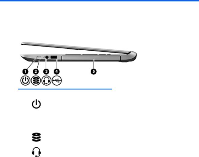
Right side
Component |
|
Description |
|
|
|
|
|
(1) |
Power light |
● |
On: The computer is on. |
|
|
● |
Blinking: The computer is in the Sleep state, a power- |
|
|
|
saving state. The computer shuts o power to the display |
|
|
|
and other unneeded components. |
|
|
● |
The computer is o or in Hibernation. Hibernation is a |
|
|
|
power-saving state that uses the least amount of power. |
|
|
|
|
(2) |
Hard drive or eMMC light |
Blinking white: The hard drive or eMMC is being accessed. |
|
|
|
|
|
(3) |
Audio-out (headphone) jack/Audio-in |
Connects optional powered stereo speakers, headphones, |
|
|
(microphone) jack |
earbuds, a headset, or a television audio cable. Also connects |
|
|
|
an optional headset microphone. This jack does not support |
|
|
|
optional microphone-only devices. |
|
|
|
WARNING! To reduce the risk of personal injury, adjust the |
|
|
|
volume before putting on headphones, earbuds, or a headset. |
|
|
|
For additional safety information, refer to the Regulatory, |
|
|
|
Safety and Environmental Notices. |
|
|
|
To access this document: |
|
|
|
Windows 8.1: |
|
|
|
From the Start screen, type support, and then select the HP |
|
|
|
Support Assistant app. |
|
|
|
‒ or – |
|
|
|
From the Windows desktop, click the question mark icon in the |
|
|
|
noti |
cation area, at the far right of the taskbar. |
Windows 10:
Select Start, select All apps, select HP Help and Support, and then select HP Documentation.
NOTE: When a device is connected to the jack, the computer speakers are disabled.
4 Chapter 2 External component identi cation
Component |
|
Description |
|
|
|
|
|
NOTE: Be sure that the device cable has a 4-conductor |
|
|
connector that supports both audio-out (headphone) and |
|
|
audio-in (microphone). |
|
|
|
(4) |
USB 2.0 port |
Connects an optional USB device, such as a keyboard, mouse, |
|
|
external drive, printer, scanner or USB hub. |
|
|
|
(5) |
Optical drive (select models only) |
Depending on your computer model, reads an optical disc or |
|
|
reads and writes to an optical disc. |
NOTE: For disc compatibility information, go to the Help and Support web page. Follow the web page instructions to select your computer model. Select Drivers & Downloads, and then follow the on-screen instructions.
In Windows 10, type help in the taskbar search box, select
Help and Support, and then type disc compatibility in the search box.
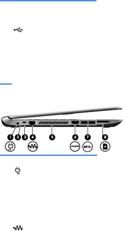
Left side
Component |
|
Description |
|
|
|
|
|
(1) |
Power connector |
Connects an AC adapter. |
|
|
|
|
|
(2) |
AC adapter light |
● |
On: The AC adapter is connected and the battery is |
|
|
|
charged. |
|
|
● |
The computer is using battery power. |
|
|
|
|
(3) |
Security cable slot |
Attaches an optional security cable to the computer. |
|
|
|
NOTE: The security cable is designed to act as a deterrent, |
|
|
|
but it may not prevent the computer from being mishandled or |
|
|
|
stolen. |
|
|
|
|
|
(4) |
RJ-45 (network) jack/status lights |
Connects a network cable. |
|
|
|
● |
White: The network is connected. |
|
|
● |
Amber: Activity is occurring on the network. |
|
|
|
|
(5) |
Vent |
Enable air ow to cool internal components. |
|
|
|
NOTE: The computer fan starts up automatically to cool |
|
|
|
internal components and prevent overheating. It is normal for |
|
|
|
the internal fan to cycle on and o during routine operation. |
|
|
|
|
|
Left side |
5 |
Component |
|
Description |
|
|
|
|
|
(6) |
HDMI port |
Connects an optional video or audio device, such as a high- |
|
|
|
de |
nition television, any compatible digital or audio |
|
|
component, or a high-speed HDMI device. |
|
|
|
|
|
(7) |
USB 3.0 ports |
Connect optional USB devices, such as a keyboard, mouse, |
|
|
|
external drive, printer, scanner or USB hub. |
|
|
|
|
|
(8) |
Memory card reader |
Reads optional memory cards that store, manage, share, or |
|
|
|
access information. |
|
|
|
To insert a card: |
|
|
|
● |
Hold the card label-side up, with connectors facing the |
|
|
|
slot, insert the card into the slot, and then push in on the |
|
|
|
card until it is rmly seated. |
|
|
To remove a card: |
|
|
|
● |
Press in on the card until it pops out. |
|
|
|
|
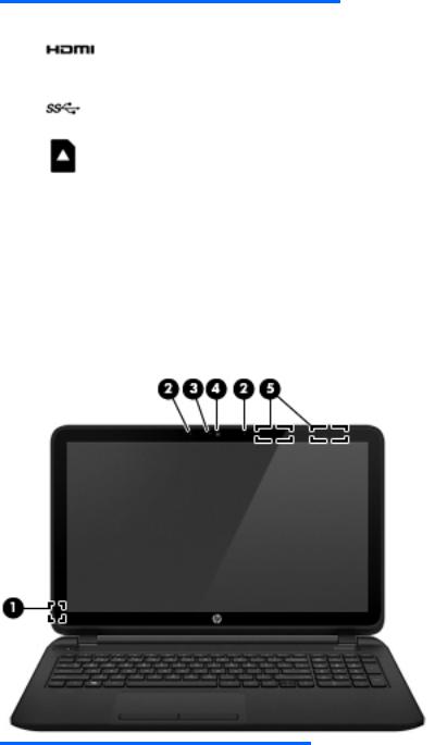
Display
Component |
Description |
|
|
|
|
(1) |
Internal display switch |
Turns o the display and initiates Sleep if the display is closed while |
|
|
the power is on. |
|
|
NOTE: The internal display switch is not visible from the outside of |
|
|
the computer. |
|
|
|
(2) |
Internal microphone |
Records sound. |
|
|
NOTE: Select models have two microphone holes. |
|
|
|
(3) |
Webcam light |
On: The webcam is in use. |
|
|
|
6 Chapter 2 External component identi cation

Component |
Description |
|
|
|
|
(4) |
Webcam |
Records video and captures photographs. Some models allow you to |
|
|
video conference and chat online using streaming video. |
|
|
To use the webcam in Windows 8.1, from the Start screen, type |
|
|
camera, and then select Camera from the list of applications. |
|
|
To use the webcam in Windows 10, type camera in the taskbar |
|
|
search box, and then select Camera. |
|
|
|
(5) |
WLAN antennas* |
Send and receive wireless signals to communicate with wireless local |
|
|
area networks (WLANs). |
*The antennas are not visible from the outside of the computer. For optimal transmission, keep the areas immediately around the antennas free from obstructions. For wireless regulatory notices, see the section of the Regulatory, Safety, and Environmental Notices that applies to your country or region.
To access this document in Windows 8.1:
From the Start screen, type support, and then select the HP Support Assistant app.
‒ or –
From the Windows desktop, click the question mark icon in the noti cation area, at the far right of the taskbar.
To access this document in Windows 10:
Select Start, select All apps, select HP Help and Support, and then select HP Documentation.
Display 7
Top
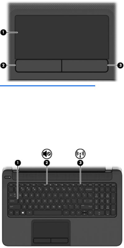
TouchPad
Component |
|
Description |
|
|
|
(1) |
TouchPad zone |
Reads your nger gestures to move the pointer or activate items |
|
|
on the screen. |
|
|
NOTE: The TouchPad also supports edge-swipe gestures. |
|
|
|
(2) |
Left TouchPad button |
Functions like the left button on an external mouse. |
|
|
|
(3) |
Right TouchPad button |
Functions like the right button on an external mouse. |
|
|
|
Lights
8 Chapter 2 External component identi cation

Component |
|
Description |
|
|
|
|
|
(1) |
Caps lock light |
On: Caps lock is on, which switches the keys to all capital letters. |
|
|
|
|
|
(2) |
Mute light |
● |
Amber: Computer sound is o . |
|
|
● |
Computer sound is on. |
|
|
|
|
(3) |
Wireless light |
On: An integrated wireless device, such as a wireless local area |
|
|
|
network (WLAN) device and/or a Bluetooth device, is on. |
|
NOTE: On some models, the wireless light is amber when all wireless devices are o .
Top 9
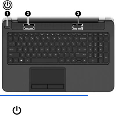
Buttons and speakers
Component |
|
Description |
|
|
|
|
|
(1) |
Power button |
● |
When the computer is o , press the button to turn on the |
|
|
|
computer. |
|
|
● |
When the computer is on, press the button brie y to initiate |
|
|
|
Sleep. |
|
|
● |
When the computer is in the Sleep state, press the button |
|
|
|
brie y to exit Sleep. |
|
|
● |
When the computer is in Hibernation, press the button |
|
|
|
brie y to exit Hibernation. |
|
|
CAUTION: Pressing and holding down the power button will |
|
|
|
result in the loss of unsaved information. |
|
|
|
If the computer has stopped responding and Windows shutdown |
|
|
|
procedures are ine ective, press and hold the power button |
|
|
|
down for at least 5 seconds to turn o the computer. |
|
|
|
To learn more about your power settings, see your power |
|
|
|
options. |
|
|
|
Windows 8.1:: |
|
|
|
▲ |
From the Start screen, type power, select Power and sleep |
|
|
|
settings, and then select Power and sleep from the list of |
|
|
|
applications. |
|
|
|
‒ or – |
|
|
|
From the Windows desktop, right-click the Start button, |
|
|
|
and then select Power Options. |
|
|
Windows 10: |
|
|
|
▲ |
Type power in the taskbar search box, and then select |
|
|
|
Power and sleep settings. |
‒ or –
10 Chapter 2 External component identi cation
Component |
Description |
Right-click the Start button, and then select Power
Options.
(2) |
Speakers |
Produce sound. |
|
|
|
Keys
Component |
|
Description |
|
|
|
(1) |
esc key |
Displays system information when pressed in combination with |
|
|
the fn key. |
|
|
|
(2) |
fn key |
Executes frequently used system functions when pressed in |
|
|
combination with the esc key or, on select models, the spacebar. |
|
|
|
(3) |
Windows key |
Windows 8.1: Returns you to the Start screen from an open app |
|
|
or the Windows desktop. |
|
|
NOTE: Pressing the Windows key again will return you to the |
|
|
previous screen. |
|
|
Windows 10: Opens the Start menu. |
|
|
NOTE: Pressing the Windows key again will close the Start |
|
|
menu. |
|
|
|
(4) |
Action keys |
Execute frequently used system functions. |
|
|
|
(5) |
num lock key |
Turns the integrated numeric keypad on and o . |
|
|
NOTE: The keypad function that is active when the computer |
|
|
is turned o is reinstated when the computer is turned back on. |
|
|
|
(6) |
Integrated numeric keypad |
When num lock has been enabled, it can be used like an external |
|
|
numeric keypad. |
|
|
|
Top 11
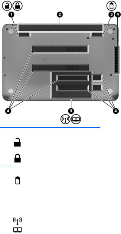
Bottom
Component |
|
Description |
|
|
|
(1) |
Battery lock |
Locks and unlocks the battery in the battery bay. |
(2) |
Battery bay |
Holds the battery. |
|
|
|
(3) |
Battery release latch |
Releases the battery. |
|
|
|
(4) |
Vents (6) |
Enable air ow to cool internal components. |
|
|
NOTE: The computer fan starts up automatically to cool |
|
|
internal components and prevent overheating. It is normal |
|
|
for the internal fan to cycle on and o during routine |
|
|
operation. |
|
|
|
(5) |
Service door |
Provides access to the wireless LAN (WLAN) module slot |
|
|
and the memory module slots. |
12 Chapter 2 External component identi cation

Component |
Description |
CAUTION: To prevent an unresponsive system, replace the wireless module only with a wireless module authorized for use in the computer by the governmental agency that regulates wireless devices in your country or region. If you replace the module and then receive a warning message, remove the module to restore computer functionality, and then contact support through Help and Support.
In Windows 8.1, from the Start screen, type h, and then select Help and Support.
In Windows 10, type support in the taskbar search box, and then select the HP Support Assistant app.
– or –
Click the question mark icon in the taskbar.
Bottom 13
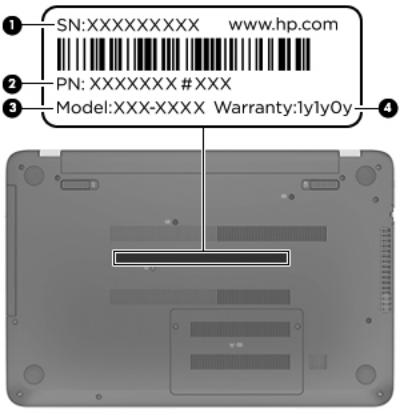
Locating system information
Important system information is located on the bottom edge of the tablet or on the keyboard base. You may need the information when travelling internationally or when you contact support:
(1): Serial number
(2): Product number
(3): Model number
(4): Warranty period
Using Windows, brie y press the fn+esc key combination to display the System Information screen, which provides the product name and serial number of your computer, as well as information about the memory, processor, BIOS, and keyboard.
14 Chapter 2 External component identi cation

3Illustrated parts catalog
Computer major components
 NOTE: HP continually improves and changes product parts. For complete and current information on supported parts for your computer, go to http://partsurfer.hp.com, select your country or region, and then follow the on-screen instructions.


 NOTE: Details about your computer, including model, serial number, product key, and length of warranty, are on the service tag at the bottom of your computer. See Locating system information on page 14 for details.
Computer major components 15

Item |
Component |
Spare part number |
|
|
|
(1) |
Display assembly: For display assembly subcomponent level spare part information, see |
not spared |
|
Display assembly subcomponents on page 19. |
|
|
|
|
|
Display assembly, touch screen |
783120-001 |
|
|
|
|
Display assembly, touch screen with HD webcam |
790204-001 |
|
|
|
|
Display assembly, touch screen, eDP |
828162-001 |
|
|
|
16 Chapter 3 Illustrated parts catalog

Item |
Component |
Spare part number |
|
|
|
(2) |
Keyboard (includes keyboard cable): |
|
|
|
|
|
For use in Canada |
776778-DB1 |
|
|
|
|
For use in Latin America |
776778-161 |
|
|
|
|
For use in the United States |
776778-001 |
|
|
|
(3) |
Top cover (includes TouchPad board and cable): |
|
|
|
|
|
Black |
776785-001 |
|
|
|
|
Red |
832758-001 |
|
|
|
|
Silver |
836863-001 |
|
|
|
(4) |
Power button board (includes cable) |
776780-001 |
|
|
|
(5) |
TouchPad button board (includes cable) |
732078-001 |
|
|
|
(6) |
Power connector bracket is available with the power connector (spare part number 732067-001) |
|
|
|
|
(7) |
Optical drive connector cable is available with the optical drive (spare part number 779456-001) |
|
|
|
|
(8) |
Audio/USB board |
732077-001 |
|
|
|
(9) |
Hard drive (does not include hard drive connector cable or hard drive rubber bracket): |
|
|
|
|
|
750 GB, 5400 rpm |
778190-001 |
|
|
|
|
500 GB, 5400 rpm |
669299-001 |
|
|
|
|
Hard Drive Hardware Kit (not illustrated, includes hard drive rubber bracket, 2 hard drive |
732071-001 |
|
retention brackets, and hard drive connector cable). |
|
(10)System board (includes replacement thermal material): All system boards use the following part numbers: xxxxxx-001: Non-Windows operating systems xxxxxx-501: Windows 8.1 Standard operating system
xxxxxx-601: Windows 8.1 Professional or Windows 10 operating system
Models with a hard drive and optical drive:
System board with Intel Core i3-4030U processor |
790202-001, -501 |
|
|
System board with Intel Core i3-4010U processor |
782103-001, -501 |
|
|
System board with Intel Core i3-4005U processor |
782101-001, -501 |
|
|
System board with Intel Pentium N3540 processor |
786901-001, -501 |
|
|
System board with Intel Pentium N3540 processor (eDP models) |
828166-001, -601 |
|
|
System board with Intel Pentium N3530 processor |
782100-001, -501 |
|
|
System board with Intel Celeron N3150 processor (eDP models) |
828169-001, -601 |
|
|
System board with Intel Celeron N3050 processor (eDP models) |
828168-001, -601 |
|
|
System board with Intel Celeron N2940 processor |
804044-001, -501 |
|
|
System board with Intel Celeron N2940 processor (eDP models) |
828165-001, -601 |
|
|
System board with Intel Celeron N2920 processor |
792575-001, -501 |
|
|
Computer major components 17

Item |
Component |
Spare part number |
|
|
|
|
System board with Intel Celeron N2840 processor |
786899-001, -501 |
|
|
|
|
System board with Intel Celeron N2840 processor (eDP models) |
828164-001, -601 |
|
|
|
|
System board with Intel Celeron N2830 processor |
779457-001, -501 |
|
|
|
|
System board with Intel Celeron N2820 processor |
789103-001, -501 |
|
|
|
|
System board with Intel Celeron N2815 processor |
789101-001, -501 |
|
|
|
|
System board with Intel Celeron N2805 processor |
787077-001, -501 |
|
|
|
|
Models with a hard drive and no optical drive: |
|
|
|
|
|
System board with Intel Core i3-4030U processor |
790201-001, -501 |
|
|
|
|
System board with Intel Core i3-4010U processor |
782104-001, -501 |
|
|
|
|
System board with Intel Core i3-4005U processor |
782102-001, -501 |
|
|
|
|
System board with Intel Pentium N3540 processor |
786900-001, -501 |
|
|
|
|
System board with Intel Pentium N3530 processor |
782106-001, -501 |
|
|
|
|
System board with Intel Celeron N2920 processor |
792574-001, -501 |
|
|
|
|
System board with Intel Celeron N2840 processor |
786898-001, -501 |
|
|
|
|
System board with Intel Celeron N2830 processor |
782105-001, -501 |
|
|
|
|
System board with Intel Celeron N2820 processor |
789102-001, -501 |
|
|
|
|
System board with Intel Celeron N2815 processor |
789100-001, -501 |
|
|
|
|
System board with Intel Celeron N2805 processor |
787076-001, -501 |
|
|
|
(11) |
Fan |
732068-001 |
|
|
|
(12) |
RTC battery |
697917-001 |
|
|
|
(13) |
Heat sink assembly (includes replacement thermal material): |
|
|
|
|
|
For computers with Intel Core processors |
742581-001 |
|
|
|
|
For computers with Intel Pentium N3540, Celeron N2940, and Celeron N2840 processors |
749040-001 |
|
|
|
|
For computers with Intel Celeron N3150 and N3050 processors |
828173-001 |
|
|
|
(14) |
Power connector (includes bracket): |
732067-001 |
|
|
|
(15) |
Hard drive connector cable is available in the hardware kit, part number 732071-001 |
|
|
|
|
(16) |
Memory modules (2, PC3L, 12800, 1600-MHz): |
|
|
|
|
|
2 GB memory module |
691739-001 |
|
|
|
|
4 GB memory module |
691740-001 |
|
|
|
|
8 GB memory module |
693374-001 |
|
|
|
(17) |
WLAN module: |
|
|
|
|
|
Ralink RT3290LE 802.11 bgn 1×1 Wi-Fi and Bluetooth 4.0 combo adapter |
690020-001 |
|
|
|
|
Realtek RTL8188EE 802.11bgn Wi-Fi Adapter for use on all computer models |
709848-001 |
|
|
|
|
Broadcom BCM43142 802.11 bgn 1x1 Wi-Fi + BT4.0 HMC Combo Adapterr |
753076-001 |
|
|
|
18 Chapter 3 Illustrated parts catalog
Item |
Component |
Spare part number |
|
|
|
(18) |
Speakers (include, speaker cables, and 4 rubber isolators) |
732084-001 |
|
|
|
(19) |
Li-ion battery |
|
|
|
|
|
4 cell, 41 Wh, 2.8 Ah |
752237-001 |
|
|
|
|
3 cell, 31 Wh, 2.8 Ah |
776622-001 |
|
|
|
(20) |
Base enclosure (includes battery release latch mechanism and RJ-45 cover) |
|
|
|
|
|
For use in models with an optical drive |
776772-001 |
|
|
|
|
For use in models without an optical drive |
777664-001 |
|
|
|
(21) |
DVD±RW Double-Layer SuperMulti Drive (includes cable, bezel, bracket, and screws) |
779456-001 |
|
|
|
(22) |
Service door (part of the plastics kit 776781-001) |
|
|
|
|
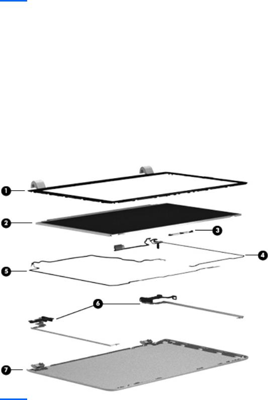
Display assembly subcomponents
Item |
Component |
Spare part number |
|
|
|
(1) |
Display bezel (includes 2 rubber screws) |
776774-001 |
|
|
|
(2) |
Raw display panel (includes 2 rubber screw covers) |
|
|
|
|
Display assembly subcomponents 19

Item |
Component |
Spare part number |
|
|
|
|
HD, BrightView |
732080-001 |
|
|
|
|
HD, BrightView, eDP |
828163-001 |
|
|
|
(3) |
Webcam/microphone module (includes adhesive) |
776787-001 |
|
|
|
|
HD webcam/microphone module (includes adhesive) |
790203-001 |
(4)Display panel cable (includes webcamera/microphone module cable and two rubber screws)
|
For use in models without eDP displays |
732066-001 |
|
|
|
|
For use in models with eDP displays |
828161-001 |
|
|
|
(5) |
Antenna Kit (includes left and right wireless antenna cables and transceivers and 2 rubber |
776770-001 |
|
screws) |
|
|
|
|
(6) |
Display Hinge Kit (includes left and right hinges and 2 rubber screws): |
732072-001 |
|
|
|
(7) |
Display back enclosure (includes 2 rubber screw covers): |
|
|
|
|
|
Black |
776771-001 |
|
|
|
|
Red |
832757-001 |
|
|
|
|
Silver |
836862-001 |
|
|
|
Miscellaneous parts
Component |
Spare part number |
|
|
|
|
45 W HP Smart AC adapter (nPFC, RC, 3-wire, 4.5 mm) |
741727-001 |
|
|
|
|
Power cord (3-pin, black, 1.00 m) |
|
|
|
|
|
For use in Denmark |
755530-081 |
|
|
|
|
For use in Europe |
755530-021 |
|
|
|
|
For use in the United Kingdom |
755530-031 |
|
|
|
|
For use in the United States |
755530-001 |
|
|
|
|
Screw Kit |
|
776782-001 |
|
|
|
HDMI to VGA Adapter |
701943-001 |
|
|
|
|
HP USB |
sh drive, 8 GB |
786830-001 |
|
|
|
HP USB |
sh drive, 8 GB, black |
829843-001 |
|
|
|
20 Chapter 3 Illustrated parts catalog
Loading...