


SAFETY
This instrument has been designed and tested according to IEC Publication 348, "Safety Requirements for Electronic Measuring apparatus," and has been supplied in safe condition . This is a Safety Class I instrument. To ensure safe operation and to keep the instrument safe, rhe information, cautions, and warnings in this manual must be heeded . Refer to Section I for general safety considerations applicable to this instrument.
CERTIFICATION
Hewlett-Packard Company certifies that this instrument met its published specifica tions at the time of shipment from the factory. Hewlett-Packard Company further certifies that its calibration measurements are traceable to the United States National Bureau of Standards, to the extent allowed by the Bureau's calibration facility, and to the calibration facilities of other International Standards Organization members.
WARRANTY AND ASSISTANCE
This Hewlett-Packard product is warranted against defects in materials and work manship for a period of one year from the date of shipment, except that in the
case |
of certain components, if any, listed in Section I of this operating manual, |
the |
warranty shall be for the specified period. Hewlett-Packard will, at its option, |
repair or replace products which pro ve to be defective during the warranty period provided they are returned to Hewlett-Packard, and provided the proper preven tive maintenance procedures as listed in this manual are followed . Repairs necessi tated by misuse of the product are not covered by this warranty. NO OTHER WARRANTIES ARE EXPRESSED OR IMPLIED, INCLUDING BUT NOT LIMITED TO THE IMPLIED WARRANTIES OF MERCHANTABILITY AND FITNESS FOR A PARTICULAR PURPOSE. HEWLETT-PACKARD IS NOT LIABLE FOR CONSEQUENTIAL DAMAGES
If this product is sold as a part of a Hewlett-Packard integrated instrument system, the above warranty shall not be applicable, and this product shall be covered only by the system warranty.
Service contracts or customer assistance agreements are available for Hewlett Packard products that require maintenance and repair on-site.
For any assistance, contact your nearest Hewlett-Packard Sales and Service Office . Addresses are provided at the back of this manual .


Con ten ts |
Modell1666A |
CONTENTS
Section |
|
|
Page |
||
|
GENERAL INFORMATION. . . . . . . . . . . . . |
I-I |
|||
|
I-I. |
Introduction.. |
|
. ...... |
I-I |
|
1-5. |
Instruments Covered by Manual |
. . . . . .. |
I-I |
|
|
1-10. |
Description |
............ |
|
I-I |
|
1-12.0ptions...... |
..._ ......... |
|
I-I |
|
|
1-14. Equipment Supplied |
........... |
|
I-I |
|
|
1-16. Equipment Required but not Supplied ... |
1-3 |
|||
|
1-18 |
Swept Amplitud e Analyzer ........ |
. |
1-3 |
|
|
1-20 |
Oscilloscope. . . . . . |
. .. |
.. . ... .. |
1-3 |
|
1-22 |
Modulator . . ... . .. |
_ ... |
_ . . . . |
1-3 |
|
1-24 |
Detector. . . . . . . . |
. ..... . . . . |
1-3 |
|
|
I-26 |
Sweep Oscillator ..... |
. __ . |
. _ . . .. |
1-3 |
|
1-28 |
Equipment Avail able ...... |
. ... |
. .... |
1-3 |
|
1-30 |
Warranty. . . . |
|
. .. . .... |
1-4 |
|
I-33 |
Recommended Test Equipmen t ........ |
|
1-4 |
|
II |
INSTALLATION |
.. . .......... |
|
2-1 |
|
|
2- 1. |
Introduction . |
. ... .. _ .... . .. |
2-1 |
|
|
2-3. |
Initial Inspection . . . . . |
.... . |
... . . ... |
2-1 |
|
2-5. |
Prepara tion for Use. |
|
|
2-1 |
|
2-6. |
Power Requirements.. . ......... |
2-1 |
||
|
2-8. |
Selecting RF Input Connector ... . ... |
2-1 |
||
|
2-10. |
Incident and Reflected Lead |
|
|
|
|
|
Identification ................ |
|
|
2-1 |
|
2-12. |
Connecting the 11 666A Retlectometer |
|
||
|
|
Bridge. . . . . . . |
|
|
2- I |
|
2-14. |
Using APC-7 RF Connectors. . . . . .. |
2-1 |
||
|
2- 16. |
Mating Connectors. |
. . |
|
2-1 |
|
2- 18. |
Operating Environment ... |
... _.. _ . |
2- 1 |
|
|
2-22. Storage and Shipment. |
. . . . . |
|
2-2 |
|
|
2-23. |
Environment ..... |
.. . __ |
. . . . .... |
2-2 |
|
2-25. |
Packaging..... . .. |
. ............ |
|
2-2 |
III |
OPERATION ......... . |
... . ........ |
.. |
3-1 |
|
|
3-1. |
Introduction......... |
. ... |
. __ .. . .. |
3-1 |
|
3-3. |
Features ... ........ |
.... |
. ... . ... |
3-1 |
|
3-5. |
Operator's Check... . |
......... |
_.... |
3-1 |
|
3-7. |
Operating In structions |
.. . ..... |
_ . . ... |
3-1 |
Section |
|
|
|
|
Page |
|
IV |
PERFORMANCE TESTS |
.. . . |
_ . _ . . . |
. . . .. |
4-1 |
|
|
4-1. |
Introduction........... |
|
...... |
.. |
4-1 |
|
4-3. |
Equipment Required. . . |
. . . . . . . |
. . |
4· 1 |
|
|
4-5. |
Test Record. . . . . . . . . . . . . . . . . . .. |
4- I |
|||
|
4-7. |
Equivalen t Directivi ty and Output |
|
|
||
|
|
SWR Test. .......... |
|
.......... |
|
4- I |
|
4-8. |
Input SWR Test ......... |
|
. . . . |
... .. |
4·6 |
|
4-9. |
Frequency Tracking Test |
.. _ ........ |
. |
4-7 |
|
V |
ADJUSTMENTS . . ....... |
_ |
... .. ..... |
_ . 5· I |
||
|
5- I. |
Introduction........ |
.. |
_ . . . . |
_ . . ... |
5· I |
|
5-3. |
Equipment Required .... |
. .... .. |
.... |
5-1 |
|
|
5-5. |
Location of Adjustment ............. |
|
|
5-1 |
|
|
5-7. |
Directional Bridge Bias Adjustment. . . .. |
5-1 |
|||
VI |
REPLACEABLE PARTS |
... . |
.... . ....... |
|
6- I |
|
|
6-1. |
Introdu ction ........ |
.......... |
|
... |
6-1 |
|
6-3. |
Abbreviations ........ |
|
_ _.. . ..... |
.. |
6-1 |
|
6-5. |
Replaceable Parts list . . |
. . . . . . . |
. . |
6· I |
|
|
6-7. |
Ordering Instructions ... |
_ . . ..... |
. ... |
6-1 |
|
VII |
MANUAL CHANGES . .......... |
|
. ...... |
|
7-1 |
|
|
7-1. |
Introduction ............. |
|
. ....... |
|
7·1 |
VIII |
SERVICE... . ... |
. . . ... . ........ 8-1 |
||||
|
8-1. |
Introducti on.. |
........... . . . . . |
8·1 |
||
|
8-3. |
Principl es of Operation .............. |
|
|
8-1 |
|
|
8-5. |
TroublesllOoting............ |
|
. . |
8- I |
|
|
8-7. |
Recommended Test Equipment. . |
. . . . . |
8- 1 |
||
|
8-9. |
Repair. |
|
|
|
8- I |
|
8-12. Printed Circuit Board Removal |
|
|
|||
|
|
and Installation. |
. . . . |
. . . . . . .. |
8-1 |
|
|
8-14. |
Changing Type N Connectors. .. |
|
8- 1 |
||
|
8-16. |
APC Connector Center Collet |
|
|
||
|
|
Replacemen t ................ |
|
|
8-1 |
|
|
8-18. |
Soldering Cable Leads. . . . . . |
. . . .. |
8-5 |
||
|
8-20. |
Soldering to Etched Circuit Boards . ... |
8-5 |
|||
|
8-22. |
Compon en t Replacement .......... |
|
8-5 |
||
|
8-23. |
Transistor Replacement. . . . . |
. |
8-5 |
||
|
8-25. Troubleshooting Procedures ..... |
. . ... |
8-6 |
|||
|
8-27. Troubleshooting Hints. |
. _ _... . .. |
8-6 |
|||
II

Model ll666A |
|
|
|
Con ten ts |
||
|
ILLUSTRATIONS |
|
|
|||
Figure |
|
Page |
Figure |
|
Page |
|
I-I . |
Model I J 666A Reflectometer Bridge with |
|
8-1. |
Prin ted Circui t Board Removal |
|
|
|
Accessories Supplied . ...... .. . . . . |
.. 1-0 |
|
and Replacemen t. .... ..... .... |
... . 8-2 |
|
2-1. |
Use of APC-7 Connectors . .. ..... . ..... |
2-2 |
8-2. |
Schematic Diagram Notes |
8-7 |
|
3-1. |
Model 11666A Features |
3-2 |
||||
8-3. |
Test Setup for Measuring AC Gain |
8-9 |
||||
3-2. |
Operator's Check |
' 3-3 |
||||
|
|
|
||||
3-3. |
Model 11666A Typical Measurement Setup .. |
3-4 |
8-4. |
Model 11666A Troubleshooting |
|
|
4-1. |
Equivalent Directivity and Output SWR |
|
|
Flow Diagram .. .......... . ....... |
8-10 |
|
|
Test Setup. . . . . . . . . . . . . . . . . . . |
4-2 |
8-5. |
Isolating Trouble to an Individual Componen t |
||
4-2 . |
Graph for Approximating Equivalent |
|
||||
|
|
in the Amplifier |
8-11 |
|||
|
Output SWR |
4-4 |
|
|||
|
8-6 . |
A4 Mas ter Board, Component Location |
8-12 |
|||
4-3. |
Input SWR Test Setup |
4-6 |
||||
|
|
|
||||
4-4. |
Frequency Tracking Test Setup ...... ... . |
4-8 |
8-7. |
Model 11666A, Schematic Diagram ....... |
8-1 3 |
|
5-1 . |
Directional Bridge Bias Adjustment Test |
|
8-8. |
A21A3 Preamplifier Component |
|
|
|
Setup |
5-1 |
|
|||
|
|
Identification Illustration |
8-14 |
|||
6-1. |
RF IN Connector J I Exploded View |
6-4 |
|
|||
|
|
|
||||
6-2. |
Model 11666A Illustrated Parts |
|
8-9. |
A21 A3 Preamplifier Assembly , |
|
|
|
Breakdown .. . ... .. . . ...... .. . .. . |
6-5 |
|
Schematic Diagram . .... ... .. ...... |
8-15 |
|
TABLES
Table |
|
Page |
Table |
|
Page |
I-I. |
Specifications ...... .... ... ..... |
.... 1-2 |
6-1. |
Reference Designators and Abbreviations |
6-1 |
1-2. |
Supplemental Characteristics .... ... . .. |
.. 1-3 |
|
Used in Manual ......... ... ..... |
|
1-3. |
Recommended Test Equipment . .... ..... |
1-5 |
|
|
6-2 |
4-1. |
Model 11666A Performance Test Record ... |
A-IO |
6-2. |
Replaceable Parts .. ... .............. |
111

Model J 1666A |
General Information |
SECTION I
GENERAL INFORMATION
1-1. INTRODUCTION
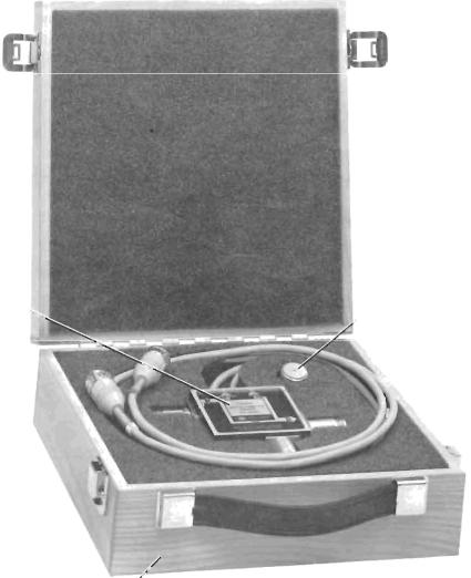
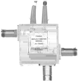
1-2. This manual contains operating and service in formation for the Hewlett-Packard Model 11666A Re flectom e ter Bridge. The instrumen t is shown in Figure I-I .
1-3. On the first page of this manual, below the manual part number, is a "Microfiche" part num ber. This number may be used to order 4x6-inch microfilm transparencies of the manual. Each microfiche contains up to 60 photo-duplicates of the manual pages. The microfiche package also in cludes the latest Manual Changes supplement as well as all pertinent Service Notes.
1-4. |
Instrument specifications are listed in Table |
1- l. |
These speci fications are performanance stan |
dards or limits against which the instrument may be tested. Table 1-2 1ists supplemental chracteristics. Supplemental characteristics are not speci fications but are typical characteristics included as additional infonnation for the user.
1-5. INSTRUMENTS COVERED 8Y MANUAL
1-6. This instrument has a two-part serial number. The first four digits and the letter comprise the serial number prefix. The last five digits form the sequential suffix that is unique to each instrument. The contents of this manual apply directly to instruments having the same serial number prefix(es) as listed under SERIAL NUMBERS on the title page.
1-7. An instrument manufactured after the printing of this manual may have a serial prefix that is not listed on the title page. This unlisted serial prefix indicates that the instrument is different from those documented in this manual. The manual for this instrument is supplied with a yellow Manual Changes supplement that contains "change information" that documents the differences.
1-8 . In addition to change information, the supple ment contains information for correcting errors in the manual. To keep this manual as current and accurate as possible, Hewlett-Packard recommends that you periodically request the latest Manual Changes sup plement. The supplement for this manual is keyed to
this manual's print date and part number, both of which appear on the title page. Complimentary copies of the supplement are available from Hewlett Packard .
1-9. For information concerning a serial number listed in the Manual Changes supplement, contact your nearest Hewlett-Packard office.
1-10. DESCRIPTION
1-11. The Model 11666A Reflectome ter Bridge is used with the HP Model 8755A Swept Amplitude Analyzer for reflection and transmission measure
men ts |
over the 40 MHz to 18 GHz frequency |
range. |
Effec ti ve external leveling is accomplished |
by measuring the ratio of Ref1ected and Test port signals to the RF input signal.
1-12. OPTIONS
1-13. The foHowing connectors are available for the 11666A:
Option 00 I : RF IN, Type N Female; TEST, Type N Male
Option 002: RF IN, Type N Female TEST, APC-7
Option 003: RF IN, APC-7; TEST, APC-7
1-14. EQUIPMENT SUPPLIED
I-IS. The equipment supplied is shown in Figure 1-1. A set of color-coded snap-on clips is also pro vided to identify the ends of the Incident and Reflected cables.
NOTE
All operation and maintenance pro cedures in this manual utilize the 116658 Modulator. The 116658 may be eliminated if the RF plug-in used is 8755A compatible. With the 116658 eliminated the 8755A MOD ULATOR DRIVE is connected to the 8620A EXT AM rear panel connector.
1- J

Generallnfonnation |
Model 11666A |
Table i-i. Specifications
SPECI FICATIONS
Frequency Range: 40 MHz to J8 GHz
Maxjmum Inpu t Power: +15 dBm (31.6 mW)
Frequency Range |
Equivalent Directivity |
||
40 to 100 MHz |
~ 30 dB |
||
0.1 to I GHz |
> 38 |
dB |
|
I to 2 |
GHz |
> 36 dB |
|
2 to 4 |
GHz |
~ 33 |
dB |
4 to 8 |
GHz |
~29 dB |
|
8 to 12 GHz |
~ 27 |
dB |
|
12 to 18 GHz |
> 26 |
dB |
|
Input SWR: .;;; 1.92
Frequency Tracking:
Between Incident and Reflected ports: .;;; 3.2 dB Bet\veen Incident and Test ports: .;;; 4.2 dB
(In cludes 11664A Detector)
Connecto rs:
Standard: Ty pe N-FemaJe (Input and Output)
Option 001: Input Type N-FemaJ e, Output Type N~\lale Option 002: Input Type N-FemaJe, Output APC-7 Option 003: APC-7 (Input and Output)
Dimensio ns :
69.9 nun wide X 69 .9 mm high X46.6 mm de ep (2.75 inches X 2.75 inches X 1.83 in che s)
Cabl e Length: 1219 mm (48 in ches)
Weight: |
Net , 0.7 kg (J.5 lb.) |
|
Shipping, 2.26 kg (5 .13 lb.) |
Equivalent Output SWR
.;;; 125
.;;; 1.25
.;;; 1.25
.;;; 1.25
.;;; 125
.;;; 127
.;;; 1.52
1-2


General Information
1-30. WARRANTY
I -3 I. Any attempt to disassemble or repair the Di rectional Bridge (A 1), Reference Termination (AT I), or TEST port (A I J3) will automatically void the war ranty. See Paragraph 8-9 in the Service section for the recommended repair procedures.
1-32. Subj ection of the |
instrument to excess ive |
RF INPUT power (>+ 15 |
dBm or 31.6 mw) will |
ModeJ 1 1666A
automatically void the warranty.
1-33. RECOMMENDED TEST EQUIPMENT
1-34 . Table I -3 lists recommended test equipment. This equipment is used in performance testing or troubleshooting the Model 1 I 666A. Other equipment may be substituted, provided its specifications equal or exceed the specifications given under Critical Specifications .
1-4
Model 1l666A
Instrument
Type
Sweep Oscillator
Swept Amplitude
Analyzer
Audio Oscillator
Modulator
Reflectometer Bridge
Detector
20-crn Air Lines (2)
Sliding Load
Coaxial Termination
General Information
Table 1-3. Recommended Test Equipment
Critical Specifications
Frequency,40MHz to 18 GHz
Provides 27.8 kHz modulation signal
Powers I 1666A Retlectometer
Bridge and 11664A Detector
Processes and displays the detected signaJs.
Recommended Model |
Use* |
HP Model 8620A mainframe with: |
P, T |
HP Model 86222 A (40 MHz to 2 GHz) |
|
HP Model 86290A (2 to 18 GHz) |
|
HP 8755 A/l82 T |
P, T |
Frequency: |
27 .8 kHz |
HP 200CD |
T |
Output: |
10 mV adjustable |
|
|
Frequency: |
40 MHz to 18 GHz |
HP 11665 B |
P, T |
Modulation: |
27.8 kHz |
|
|
|
|
HP 11666A |
P |
Frequency: |
40 MHz to 18 GHz |
HP 11 664A |
P,T |
Frequency: |
40 MHz to 18 GHz |
I-lP 11567 A |
P |
Frequency: |
2 GHz to 18 GHz |
HP905A |
P |
Load SWR: |
,;;; 1.05 |
|
|
Frequ ency: |
40 MHz to 2 GHz |
HP 909A Option 012 |
P |
Load SWR: |
,;;; 1.05 |
|
|
Connector: |
Type N MaJe |
|
|
Coaxial Short |
Fits 11666A TEST port connector |
HP 11512A (Type N Male) |
P |
|
|
|
|
HP J 1511A (Type N Female) |
|
|
|
|
HP 11565A (APC-7) |
|
Open-End Wrench |
Thin 1/2 x 9/l6-inch wrench |
HP Part No. 87 10-0877 |
P, T |
|
Soldering Iron |
Wattage: |
37.5 watts |
Ungar No. 776 Handle with |
T |
|
Tip Temp : |
750 to 800 0 F |
Ungar No. 1237 Heating Unit |
|
|
Tip Size: |
1/8" 00 |
|
|
Soldering Tip |
Shape: |
cllisel |
Ungar No. PL 113 |
T |
|
Size: |
1/8" |
|
|
De-soldering Aid |
Su ction device to remove |
Soldavac by the Edsyn Company, |
T |
|
|
molten solder from connection |
Arleta, Cali fornia |
|
|
Protective Coating |
Good electIica l insulation , |
Krylon No. 1302 |
T |
|
|
corrosion-prevention properties |
|
|
|
OsciUosco pe |
Vert. Bandwidth: ~250 kHz |
HP 182 A/ 180 I A/ 1802 C |
T |
|
|
Vert. Sensitivity: >1 mV/cm |
|
|
|
"P = Performance Testing |
T = Troubleshooting |
|
|
|
1-5/1-6

Model I t666A |
Installation |
SECTION II
INSTALLATION
2-1. INTRODUCTION
2-2. This section contains information concerning initial inspection, preparation for use, mating connec tors, and storage and shipment.
2-3. INITIAL INSPECTION
2-4 . If the shipping container or cushioning material is damaged, it should be kept until the contents of the shipment have been checked for completeness and the instrument has been checked mechanically and elec trically. The contents of the shipment should be as shown in Figure I-I . Procedures for checking electri cal performance are given in Section IV. If the con tents are incomplete, if there is mechanical damage or defect, or if the instrument does not pass the electrical performance test, notify the carrier as well as the Hewlett-Packard office. Keep the shipping materials for the carrier's inspection. The HP office will arrange for repair or replacement without waiting for claim settlement.
2-5. PREPARATION FOR USE
2-6. Power Requirements
2- 7. Power for the Model 11666A Reflectometer Bridge is obtained from the Model 8755A Swept Amplitude Analyzer.
2-8. Selecting RF Input Connector
2-9. The RF Input Connector outer shell and inner conductor assembly may be replaced, thereby chang ing the type of RF Input connector. This can be done by the operator using a thin open-end wrench. Refer to the Service section of this manual, Paragraph 8-14 for details.
2-10. Incident and Reflected Lead Identifica tion
2- 1I. Colored clip-on clips are furnished for lead identification. Place matching clips on both ends of each cable.
2-12. Connecti ng the 11666A Reflectometer Bridge
2-13 . To connect the 11666A to the 8755A, proceed as follows:
a. Insert the 11666A dc connectors into the corres ponding 8755A mating connectors INDICENT to Channel Rand REFL to Channel A. The co nnec tors are keyed and the plug should be inserted with the key facing down wards.
b.Secure the dc connector in the 8755A turning the outer shell clockwise. This tightens the connector.
c.To connect the RF Input
I. Read CAUTION in paragraph 3-8.
2.If either connector is an APC-7, refer to Figure 2-1 for instructions.
2-14. Using APC-7 RF Connectors
2- I 5. Figure 2-1 shows the use of APC-7 connec tors . Read the instructions on this figure before at tempting to use APC-7 connectors.
2-16. Mating Connectors
2-17. Mating connectors for Type N connectors are the corresponding Type N connectors whose dimensions conform to US specification MIL-C 39012. Mating connectors for the APC-7 connec tors are other APC-7 connectors. Mating connec tors for other connector types are the corres ponding connector of the same series.
2-18. Operating Environment
2-19. Temperature. The instrument may be op
erated in temperatures from - 25°C to 55°C.
2-20. Humidity. The instrument may be operat ed in environments with humidity up to 95%. However, the instrumen ts should also be protected from tempe rature extremes which cause conden sation within the 11666A.
2-1


Section III |
Operation |
SECTION III
OPERATION
3-1. INTRODUCTION
3-2. This section contains instructions concerning operation of the Model 11666A Reflectometer Bridge.
3-3. FEATURES
3-4. Features of the Model 11666A are shown In Figure 3-1.
3-5. OPERATOR'S CHECK
3-6. Figure 3-2 is an operator's check procedure, allowing the operator to make a quick check of the main system functions prior to use. The test covers the
entire measurement system and incorrect indications may be caused by any portion of the system. If the
Reflectometer Bridge is suspected, use the perfor mance tests in Section IV to determine if the Reflec
tometer Bridge is working correctly. Otherw ise, fol low the troubleshooting tree in Section VIII to isolate the problem.
3-7. OPERATING INSTRUCTIONS
3-8. Figure 3-3 provides instruc tions for making reflection and transmission measurements. The test setup in Figure 3-3 shows a typical reflectometer test setup for simultaneollsly measuring reflection and transmission characteristics of a device under test.
Do NOT apply more than + 15 dBm RF Power or more than ± 10 volts de into the 11666A. If more than this power or voltage is applied, the 11666A will be damaged.
3-1


 Loading...