


11 G5

HP Chromebook and HP Chromebook 11 G5
Maintenance and Service Guide
IMPORTANT! This document is intended for
HP authorized service providers only.

© Copyright 2016 HP Development Company,
L.P.
Bluetooth is a trademark owned by its
proprietor and used by HP Inc. under license.
Intel and Celeron are trademarks of Intel
Corporation in the U.S. and other countries. SD
Logo is a trademark of its proprietor.
The information contained herein is subject to
change without notice. The only warranties for
HP products and services are set forth in
the express warranty statements
accompanying such products and services.
Nothing herein should be construed as
constituting an additional warranty. HP shall
not be liable for technical or editorial errors or
omissions contained herein.
First Edition: July 2016
Document Part Number: 854544-001
Product notice
This guide describes features that are common
to most models. Some features may not be
available on your computer.

Safety warning notice
WARNING! To reduce the possibility of heat-related injuries or of overheating the device, do not place
the device directly on your lap or obstruct the device air vents. Use the device only on a hard, at surface. Do
not allow another hard surface, such as an adjoining optional printer, or a soft surface, such as pillows or rugs
or clothing, to block airow. Also, do not allow the AC adapter to contact the skin or a soft surface, such as
pillows or rugs or clothing, during operation. The device and the AC adapter comply with the user-accessible
surface temperature limits dened by the International Standard for Safety of Information Technology
Equipment (IEC 60950-1).
iii

iv Safety warning notice

Table of contents
1 Product description ....................................................................................................................................... 1
2 External component identication .................................................................................................................. 3
Right side ............................................................................................................................................................... 3
Left side ................................................................................................................................................................. 4
Display .................................................................................................................................................................... 5
Top .......................................................................................................................................................................... 6
TouchPad ............................................................................................................................................. 6
Button .................................................................................................................................................. 7
Bottom ................................................................................................................................................................... 8
Labels ..................................................................................................................................................................... 8
3 Illustrated parts catalog .............................................................................................................................. 10
Computer major components .............................................................................................................................. 11
Display assembly subcomponents ...................................................................................................................... 14
Miscellaneous parts ............................................................................................................................................. 16
4 Removal and replacement preliminary requirements ..................................................................................... 18
Tools required ...................................................................................................................................................... 18
Service considerations ......................................................................................................................................... 18
Plastic parts ....................................................................................................................................... 18
Cables and connectors ...................................................................................................................... 18
Drive handling ................................................................................................................................... 19
Grounding guidelines ........................................................................................................................................... 20
Electrostatic discharge damage ........................................................................................................ 20
Packaging and transporting guidelines .......................................................................... 21
Workstation guidelines ................................................................................ 21
5 Removal and replacement procedures ........................................................................................................... 23
Component replacement procedures .................................................................................................................. 23
Computer feet ................................................................................................................................... 23
Keyboard/top cover ........................................................................................................................... 24
WLAN module .................................................................................................................................... 27
Hall sensor board .............................................................................................................................. 28
Connector board and cable ............................................................................................................... 29
Battery ............................................................................................................................................... 30
v

Speakers ............................................................................................................................................ 32
System board .................................................................................................................................... 33
Heat sink ............................................................................................................................................ 35
Display assembly ............................................................................................................................... 37
Power connector and cable ............................................................................................................... 43
6 Specications .............................................................................................................................................. 45
7 Power cord set requirements ........................................................................................................................ 46
Requirements for all countries ............................................................................................................................ 46
Requirements for specic countries and regions ................................................................................................ 47
8 Recycling .................................................................................................................................................... 49
Index ............................................................................................................................................................. 50
vi

1 Product description
Category Description
Product Name HP Chromebook
HP Chromebook 11 G5
Processor Intel® Celeron® N3060 1.60 GHz (SC turbo up to 2.48 GHz) 1600
MHz/2 MB L2, Dual 6 W TDP, 4 W SDP
Chipset Integrated soldered-on-circuit (SoC) integrated with processor
Graphics Internal Graphics: Intel HD Graphics
Supports HD decode, DX12, and HDMI
Panel 11.6 in, high-denition (HD), AntiGlare, (1366×768), SVA, white
light-emitting diode (WLED), non-touch, at (3.6 mm); 16:9
aspect ratio; typical brightness: 220 nits, eDP, non-touch sku (for
use with HP Chromebook models only)
11.6 in, high-denition (HD), AntiGlare, (1366×768), UWVA, white
light-emitting diode (WLED), non-touch, slim (3.0 mm); 16:9
aspect ratio; typical brightness: 220 nits, eDP, non-touch sku
11.6 in, HD, (1366×768), SVA, WLED, touch, at (3.0 mm); 16:9
aspect ratio; typical brightness: 220 nits, eDP, touch solution with
Gorilla Glass NBT, multi-touch enabled.
Memory Supports up to 4096 MB maximum on-board system memory.
LPDDR3-1600 single channel (LPDDR3-1866 downgraded to
LPDDR3-1600)
2048 MB (8 GB, 128 M x 32 x 2 x 2 pcs and 4096 MB (8 GB, 128 M x
32 x 2 x 4 pcs
Storage Supports 16 GB (32 GB for HP Chromebook 11 G5) embedded
MultiMedia Controller (eMMC)
Audio and video Dual speakers
Fixed (no tilt) integrated HP TrueVision HD camera
1280×720 by 30 frames per second with LED
Single digital microphone with appropriate echo-cancellation,
noise-suppression software
Security Mini-Kensington security lock
Ultraslim Kensington Security Lock (for use with HP Chromebook
11 G5 models only)
Wireless Integrated wireless local area network (WLAN) options by way of
wireless module.
Two built-in WLAN antennas
Supports Intel Dual Band Wireless 7265 802.11 AC 2 x 2 WiFi +
Bluetooth® 4.2 Combo Adapter
Ports
●
HP Smart Plug AC adapter (4.5 mm barrel)
1

Category Description
●
Headphone/microphone combo jack
●
High-denition multimedia interface (HDMI) v.1.4b,
supporting up to 1080b, 1920×1080 at 60 Hz
●
USB 3.0 ports (2)
●
Connector board
Keyboard/pointing devices Full-size, textured, island-style, Google keyboard, ash gray
Touchpad requirements:
Clickpad with image sensor
Multitouch gestures enabled
Taps enabled as default
Power requirements Supports a 2-cell, 43.7 Wh, polymer battery
Supports a 65 W HP Smart AC adapter (non-PFC, EM, 4.5 mm) and
45 W HP Smart AC adapter (non-PFC, RC, 4.5 mm) AC adapter
Operating system Preinstalled: Google Chrome operating system
Serviceability End user replaceable parts: AC adapter
2 Chapter 1 Product description

2 External component identication
Right side
Component Description
(1) USB 3.0 charging (powered) port Connects an optional USB device, such as a keyboard,
mouse, external drive, scanner or USB hub. Standard
USB ports will not charge all USB devices or will charge
using a low current. Some USB devices require power
and require you to use a powered port.
(2) HDMI port Connects an optional video or audio device, such as a
high-denition television, any compatible digital or
audio component, or a high-speed High-Denition
Multimedia Interface (HDMI) device.
(3) MicroSD card reader Reads optional memory cards that store, manage,
share, or access information.
(4) AC adapter and battery light
●
White: The AC adapter is connected and the
battery is charged.
●
Amber: The AC adapter is connected and the
battery is charging.
●
O: The computer is using battery power.
(5) Power connector Connects an AC adapter.
Right side 3

Left side
Component Description
(1) Security cable slot Attaches an optional security cable to the computer.
NOTE: The security cable is designed to act as a
deterrent, but it may not prevent the computer from
being mishandled or stolen.
(2) USB 3.0 charging (powered) port Connects an optional USB device, such as a keyboard,
mouse, external drive, scanner or USB hub. Standard
USB ports will not charge all USB devices or will
charge using a low current. Some USB devices require
power and require you to use a powered port.
(3) Audio-out (headphone)/Audio-in
(microphone) combo jack
Connects optional powered stereo speakers,
headphones, earbuds, a headset, or a television audio
cable. Also connects an optional headset microphone.
This jack does not support optional standalone
devices.
WARNING! To reduce the risk of personal injury,
adjust the volume before putting on headphones,
earbuds, or a headset.
NOTE: When a device is connected to the jack, the
computer speakers are disabled.
NOTE: Be sure that the device cable has 4-
conductor connector that supports both audio-out
(headphone) and audio-in (microphone).
(4) Duplicate power light
●
White: Computer is on.
●
Pulsing white: Computer is in the sleep state.
●
O: Computer is o.
4 Chapter 2 External component identication

Display
Component Description
(1) WLAN antennas* Send and receive wireless signals to communicate with wireless local
area networks (WLANs).
NOTE: WLAN antennas are not visible on the exterior of the device.
(2) Internal microphones** Record sound.
(3) Camera light On: The camera is in use.
(4) HD camera Record video and capture still photographs in HD resolution
*The antennas and sensors are not visible from the outside of the computer. For optimal transmission, keep the areas immediately
around the antennas and sensors free from obstructions. For wireless regulatory notices, see the section of the Regulatory, Safety,
and Environmental Notices that applies to your country or region.
** The position of the internal microphones may dier, depending on the model.
Display 5
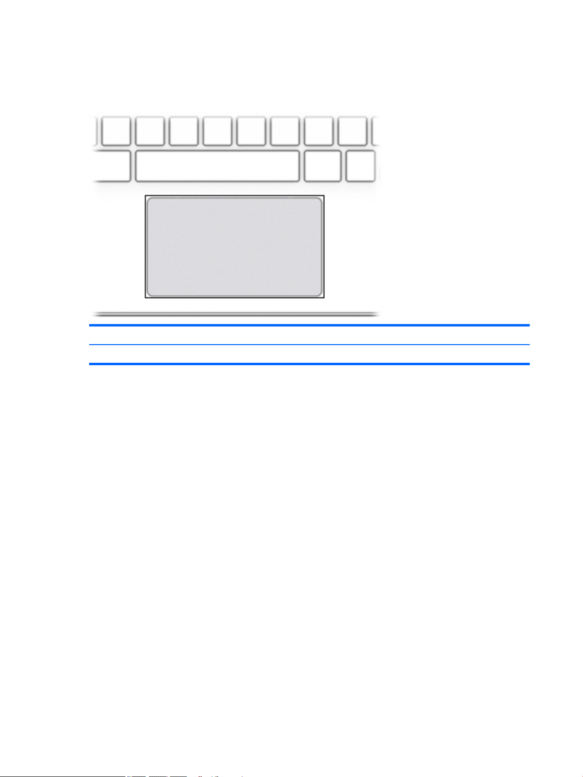
Top
TouchPad
Component Description
TouchPad Reads your nger gestures to move the pointer or activate items on the screen.
6 Chapter 2 External component identication

Button
Component Description
Power button
●
When the computer is o, press the button to turn on the
computer.
●
When the computer is in the Sleep state, press the button
briey to exit Sleep.
●
When the computer is on and you want to lock the screen,
press the button until you see the sign-in screen appear.
Pressing the power button during screen-lock mode turns
o the computer.
●
When the computer is on and you want to turn it o, press
and hold the button to lock the screen, and then continue
to press the button until the computer powers o.
Top 7
Bottom
Component Description
Speakers (2) Produce sound.
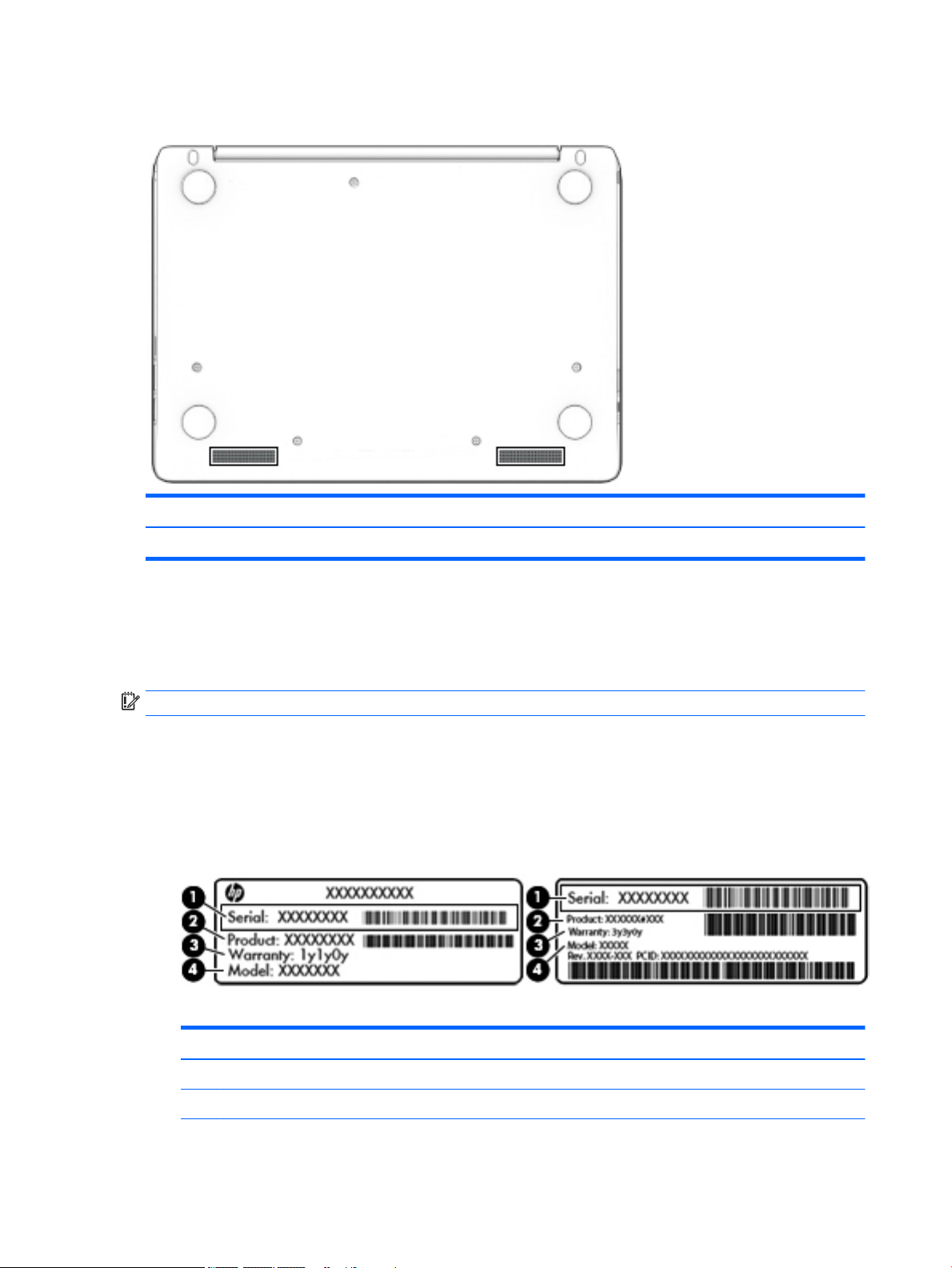
Labels
The labels axed to the computer provide information you may need when you troubleshoot system
problems or travel internationally with the computer.
IMPORTANT: All labels described in this section will be axed to the bottom of the computer.
●
Service label—Provides important information to identify your computer. When contacting support, you
will probably be asked for the serial number, and possibly for the product number or the model number.
Locate these numbers before you contact support.
Your service label will resemble one of the examples shown below. Refer to the illustration that most
closely matches the service label on your computer.
Component
(1) Serial number
(2) Product number
8 Chapter 2 External component identication

Component
(3) Warranty period
(4) Model number (select products only)
Component
(1) Model name (select products only)
(2) Product number
(3) Serial number
(4) Warranty period
●
Regulatory label(s)—Provide(s) regulatory information about the computer.
●
Wireless certication label(s)—Provide(s) information about optional wireless devices and the approval
markings for the countries or regions in which the devices have been approved for use.
Labels 9

3 Illustrated parts catalog
NOTE: HP continually improves and changes product parts. For complete and current information on
supported parts for your computer, go to http://partsurfer.hp.com, select your country or region, and then
follow the on-screen instructions.
10 Chapter 3 Illustrated parts catalog

Computer major components
Computer major components 11

Item Component Spare part number
(1) Display assembly: Non-touch display assemblies are spared at the subcomponent level
only. For display assembly spare part information, see Display assembly subcomponents
on page 14.
The HP Chromebook 11 G5 model touch displays are only spared as full hinge-ups.
Individual components are not spared for these touch screen displays.
901252-001
(2) Keyboard/top cover (includes keyboard cable):
NOTE: Keyboard/top cover is spared with the TouchPad under spare part kits with spare part numbers 900818-xxx. The
TouchPad cable spare part number is 900814-001.
For use with HP Chromebook and HP Chromebook 11 G5 models
For use in Belgium 900818-A41
For use in Canada 900818-DB1
For use in Denmark, Finland, and Norway 900818-DH1
For use in France 900818-051
For use in Germany 900818-041
For use in Italy 900818-061
For use in the Netherlands 900818-B31
For use in Russia 900818-251
For use in Romania 900818-271
For use in Spain 900818-071
For use in Switzerland 900818-BG1
For use in the United Kingdom 900818-031
For use in the United States 900818-001
For use with HP Chromebook 11 G5 models only
For use in the Czech Republic and Slovenia 900818-FL1
For use in Israel 900818-BB1
For use in Japan 900818-291
For use in Saudi Arabia 900818-171
For use in Taiwan 900818-AB1
For use in Thailand 900818-281
(3) System board (includes replacement thermal material):
Intel Celeron N3060 2.16 GHz, 2.0 GB of system memory, and 16 GB of eMMC system
storage
900041-001
Intel Celeron N2840 2.16 GHz, 4.0 GB of system memory, and 16 GB of eMMC system
storage
900042-001
Intel Celeron N2840 2.16 GHz, 4.0 GB of system memory, and 32 GB of eMMC system
storage (for use with HP Chromebook 11 G5 models only)
901250-001
(4) WLAN module:
12 Chapter 3 Illustrated parts catalog
 Loading...