


Operating Instructions
GB RS
English, 1 |
Русский, 12 |
7OFZ G RU /HA
7OFZ G IX RU /HA
7OFH G RU/HA
7OFH G IX RU/HA
7OFHRG RU/HA
OVEN
Contents
GB
Installation, 2-5
Positioning Electrical connection Gas connection Data plate
Description of the appliance, 6
Overall view
Control panel
Start-up and use, 7-8
Starting the oven
How to use the timer
Burner and nozzle specifications
Cooking modes, 9
Cooking modes
Practical cooking advice
Cooking advice table
Precautions and tips, 10
General safety
Disposal
Respecting and conserving the environment
Maintenance and care, 11
Switching the appliance off
Cleaning the appliance
Cleaning the oven door
Replacing the light bulb
Assistance

Installation
Before operating your new appliance please read GB this instruction manual carefully. It contains important
information for safe use, installation and care of the appliance.
Please keep these operating instructions for future reference. Pass them on to possible new owners of the appliance.
Positioning
Keep packaging material out of the reach of children. It can become a choking or suffocation hazard (see Precautions and tips).
The appliance must be installed by a qualified person according to the instructions provided. Incorrect installation may cause harm to people and animals or may damage property.
This appliance should only be installed and used in permanently ventilated rooms in compliance with current National regulations. The following requirements must be observed:
•The room must be equipped with an air extraction system that expels any combustion fumes. This may consist of a hood or an electric fan that automatically starts each time the appliance is switched on.
|
|
|
|
|
|
|
|
|
|
|
|
|
|
|
|
|
|
|
|
|
|
|
|
|
|
|
|
|
|
|
|
|
|
|
|
|
|
|
|
|
|
|
|
|
|
|
|
|
|
|
|
|
|
|
|
|
|
|
|
|
|
|
|
|
|
|
|
|
|
|
|
|
|
|
|
|
|
|
|
|
|
|
|
|
|
|
|
|
|
|
|
|
|
|
|
|
|
|
|
|
|
|
|
|
|
|
|
|
|
|
|
In a chimney stack or branched flue. |
Directly to |
|
|
||||||||||||
(exclusively for cooking appliances) |
the Outside |
|
|
||||||||||||
|
|
|
|
|
|
|
|
|
|
|
|
|
|
|
|
•The room must also allow proper air circulation, as air is needed for combustion to occur normally. The
flow of air needed for combustion must not be less than 2 m3/h per kW of installed power.
The air circulation system may take air directly from the
outside by means of a pipe with an inner cross section of at least 100 cm2; the opening must not be vulnerable to any type of blockages.
A
Examples of ventilation holes for comburant air.
The system can also provide the air needed for combustion indirectly, i.e. from adjacent rooms fitted with air circulation tubes as described above. However, these rooms must not be communal rooms, bedrooms or rooms that may present a fire hazard.
•Liquid petroleum gas sinks to the floor as it is heavier than air. Therefore, rooms containing LPG cylinders must also be equipped with vents to allow gas to escape in the event of a leak. As a result LPG cylinders, whether partially or completely full, must not be installed or stored in rooms or storage areas that are below ground level (cellars, etc.). It is a good idea to keep only the cylinder being used in the room, positioned so that it is not subject to heat produced by external sources (ovens, fireplaces, stoves, etc. ) which could raise the temperature of the cylinder above 50°C.
Fitting the appliance
Use a suitable kitchen unit to ensure that the appliance functions properly.
•The panels adjacent to the oven must be made from heat-resistant material.
•Cabinets with a veneer exterior must be assembled with a glue that can withstand temperatures of up to 100°C.
•To install the oven under the counter (see diagram) or in a kitchen unit, the cabinet must have the following dimensions:
|
|
|
|
|
|
|
in. |
|
|
|
|
|
|
|
.m |
|
|
|
|
|
mm.23 |
|
|
mm |
|
mm. |
|
|
|
|
547 |
|
|||
|
|
|
|
|
|
|
. |
|
|
|
|
|
|
45 |
mm |
|
|
|
|
|
|
|
|
|
|
|
mm.595 |
|
|
|
mm.567 |
|
558 |
m |
593 |
|
|
|
|
|
||||
|
|
|
|
|
|
|
m. |
|
|
|
|
5 mm. |
|
|
|
|
|
595 |
|
|
|
m |
|
|
|
|
|
m |
|
|
. |
|
|
|
|
|
m. |
545 |
m |
|
|
|
|
|
|
|
|
|
|
|
|
||
|
|
|
|
|
|
|
|
|
|
|
. |
|
|
|
|
|
|
|
|
m |
|
|
|
|
|
|
|
m |
|
|
|
|
|
|
|
24 |
|
|
|
|
|
|
|
|
The appliance must not come into contact with electrical parts once it has been installed.
The figures indicated on the data plate have been calculated for this type of installation.
2
 User manual")
Ventilation
To ensure adequate ventilation, the back panel of the cabinet must be removed. It is advisable to install the oven so that it rests on two strips of wood, or on a completely flat surface with an opening of at least 45 x 560 mm (see diagrams).
|
|
. |
45 |
mm |
|
|
|
m |
|
. |
|
|
0 |
m |
|
|
|
6 |
|
|
|
|
|
5 |
|
|
|
|
|
Centring and fastening
Position the 4 tabs on the side of the oven according to the 4 holes on the outer frame. Adjust the tabs according to the thickness of the cabinet side panel, as shown below:
20 mm thick: take off the removable part of the tab (see diagram).
18 mm thick: use the first groove, which has already been set in the factory (see diagram).
16 mm thick: use the second groove (see diagram).
Secure the appliance to the cabinet by opening the oven door and fastening 4 screws into the 4 holes of the outer frame.
All parts ensuring the safe operation of the appliance must not be removable without the aid of a tool.
GB
Electrical connections
Ovens equipped with a three-pole power supply cable are designed to operate with alternating current at the voltage and frequency indicated on the data plate located on the appliance (see below).
Fitting the power supply cable
1. Open the terminal board by inserting a screwdriver into the side tabs of the cover. Use the screwdriver as a lever by pushing it down to open the cover (see diagram).
2.Loosen the cable clamp screw and remove it, using a screwdriver as a lever (see figure).
3.Remove the wire contact
screws L-N-  , then fasten the wires under the screw heads, respecting the colour code: Blue (N), Brown (L) and Yellow-Green Verde (
 ).
).
Connecting the supply cable to the mains
Install a standardised plug corresponding to the load indicated on the data plate (see adjacent box). The appliance must be directly connected to the mains using an omnipolar circuit-breaker with a minimum contact opening of 3 mm installed between the appliance and the mains. The circuit-breaker must be suitable for the charge indicated and must comply with current electrical regulations (the earthing wire must not be interrupted by the circuitbreaker). The supply cable must not come into contact with surfaces with temperatures higher than 50°C.
The installer must ensure that the correct electrical connection has been made and that it is compliant with safety regulations.
3
Before connecting to the power supply, make sure GB that:
•the appliance is earthed and the plug is compliant with the law.
•the socket can withstand the maximum power of the appliance, which is indicated on the data plate (see below).
•the voltage is in the range between the values indicated on the data plate (see below).
•the socket is compatible with the plug of the appliance. If the socket is incompatible with the plug, ask an authorised technician to replace it. Do not use extension cords or multiple sockets.
Once the appliance has been installed, the power supply cable and the electrical socket must be easily accessible.
The cable must not be bent or compressed.
The cable must be checked regularly and replaced by authorised technicians only (see Assistance).
The manufacturer declines any liability should these safety measures not be observed.
Gas connection
The appliance should be connected to the main gas supply or to a gas cylinder in compliance with current National regulations. Before carrying out the connection, make sure the cooker is compatible with the gas supply you wish to use. If this is not the case, follow the instructions indicated in the paragraph “Adapting to different types of gas.” When using liquid gas from a cylinder, install a pressure regulator that complies with current National regulations.
Check that the pressure of the gas supply is consistent with the values indicated in Table 1 (“Burner and nozzle specifications”) since this will ensure the safe operation and longevity of your appliance while maintaining efficient energy consumption.
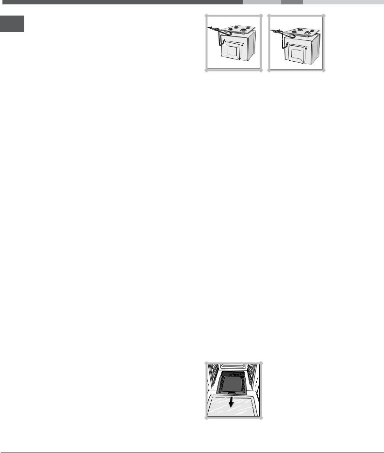
Should you need to install a gas hob on top of a built-in gas oven, it is strictly forbidden to connect the two or to use a single cut-off tap. The two appliances should be connected separately, and each one should have its own stop tap in order to make them completely independent from one another (see figures).
NO |
OK |
Connection with a rigid pipe (copper or steel)
Connection to the gas system must be carried out in such a way as not to place any strain of any kind on the appliance.
There is an adjustable L-shaped pipe fitting on the appliance supply ramp and this is fitted with a seal in order to prevent leaks. The seal must always be replaced after rotating the pipe fitting (the seal is provided with the appliance). The gas supply pipe fitting is a threaded 1/2 gas cylindrical male attachment.
Connecting a flexible jointless stainless steel pipe to a threaded attachment
The gas supply pipe fitting is a threaded 1/2 gas cylindrical male attachment.
These pipes must be installed so that they are never longer than 2000 mm when fully extended. Once connection has been carried out, make sure that the flexible metal pipe does not touch any moving parts and is not compressed.
Only use pipes and seals that comply with current National regulations.
Checking the tightness of the connection
When installation has been completed, check the pipe fittings for leaks using a soapy solution. Never use a flame.
Adapting to different types of gas
In order to adapt the oven to a type of gas other than the type for which it was manufactured (indicated on the label), follow these simple steps:
• Replacing the oven burner nozzle 1. Open the oven door fully.
2. Slide out the bottom of the oven.
4

V |
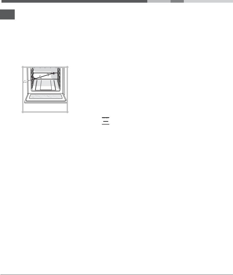
3.Unscrew the burner fastening screws.
4.Remove screw “V” and then the oven burner.
5. Unscrew the oven burner nozzle using the special socket spanner for the nozzles, or better still a 7 mm socket spanner, and replace it with a nozzle suited to the new type of gas (see Table 1).
6.Replace all the parts, following the steps described above in the reverse order.
Take particular care when handling the spark plug wires and the thermocouple pipes.
•Primary air regulation for the oven burner The burner was designed not to need any adjustments to the primary air.
•Setting the oven burner to minimum
1.Turn the knob first to the Max setting for about 10 minutes and then to Min.
2.Remove the knob.
3.Remove the disk fastened to the control panel.
4.Adjust the screw located outside the thermostat cock pin until the flame is small but steady (the flame can be seen through the slots on the oven bottom).
5. Make sure the burner does not switch off when |
GB |
you turn the knob from Max to Min quickly, or |
|
when you open and close the oven door quickly. |
|
|
If the appliance is connected to liquid gas, the regulation screw must be fastened as tightly as possible.
Once this procedure is finished, replace the old rating sticker with one indicating the new type of gas used. This sticker is available from any of our Service Centres.
If the gas pressure is different from the recommended pressure, a suitable pressure regulator must be fitted to the inlet pipe in accordance with current National Regulations.
DATA PLATE
|
width 43.5 cm |
|
Dimensions |
height 31 cm |
|
|
depth 43.5 cm |
|
Volume |
58 l |
|
Electrical |
see data plate |
|
connections |
||
|
||
Gas features |
see data plate |
|
|
This appliance conforms to the |
|
|
following European Economic |
|
|
Community directives: |
|
|
2006/95/EEC dated 12/12/06 |
|
|
(Low Voltage) and subsequent |
|
|
amendments - 2004/108/EEC |
|
|
dated 15/12/04 (Electromagnetic |
|
|
compatibility) and subsequent |
|
|
amendments - 93/68/EEC dated |
|
|
22/07/93 and subsequent |
|
|
amendments. 90/336/EEC dated |
|
|
29.06.90 (Gas) and subsequent |
|
|
amendments. |
|
|
2002/96/EC and subsequent |
|
|
amendments. |
5

Description of the appliance
Overall view
GB
Control panel |
GUIDES for the |
|
|
sliding racks |
|
GRILL |
position 5 |
|
|
position 4 |
|
DRIPPING PAN |
position 3 |
|
position 2 |
||
|
||
|
position 1 |
Control panel
|
|
GRILL |
|
TIMER |
|
|
indicator light |
|
knob |
|
|
0 |
|
|
|
|
|
0 |
|
|
|
|
1 |
|
|
|
Min |
|
|
|
|
|
45 |
15 |
Max |
|
150 |
|
|
|
220 |
180 |
|
30 |
|
|
|
||
|
|
OVEN/GRILL |
OVEN LIGHT |
|
|
|
knob |
button |
|
6

Start-up and use
The first time you use your appliance, heat the empty oven with its door closed at its maximum temperature for at least half an hour. Ensure that the room is well ventilated before switching the oven off and opening the oven door. The appliance may produce a slightly unpleasant odour caused by the burning away of protective substances used during the manufacturing process.
Starting the oven
This knob is used not only to select the different oven modes, but also to choose the right cooking temperature for various foods from among the temperatures shown on the knob itself (the range is from 140°C to 240°C inclusive). The electronic ignition device of the oven is built into the control knob. To light the oven burner, press the OVEN knob in as far as possible and turn it anti-clockwise, setting it to position (keeping the oven door shut). The oven is equipped with a safety device. After lighting the burner allow the gas to circulate until the safety thermocouple is heated by keeping the OVEN knob pressed in for about 6 seconds.
The electronic ignition device of the oven burner must not be activated for more than 15 seconds. If the burner fails to light after 15 seconds, stop pressing the OVEN knob, open the oven door and wait for at least one minute before you try to light the burner again.
The cooking temperature is selected by matching the desired temperature with the reference mark on the control panel; the complete range of temperatures is shown below:
Min |
• |
150 • |
180 • |
220 • |
Max |
|
|
|
|
|
|
" |
"# |
$ |
|
! |
" |
|
|
|
|
|
|
The oven will automatically reach the temperature set, and the thermostat, which is controlled by the knob, will keep the temperature constant.
Switching the oven on manually
GB
In the event of a power failure, the oven burner can be lit manually:
1. Open the oven door.
F |
2. Hold a match or lighter near the burner hole as shown in the figure, press knob F (see figure) in fully and turn it anticlockwise, setting it to the Max position.
The oven is equipped with a safety device. After lighting the burner allow the gas to circulate until the safety thermocouple is heated by keeping the OVEN knob pressed in for about 6 seconds.
3. Once the burner is lit, shut the oven door.
If the burner flame is accidentally extinguished, turn the OVEN control knob to the off position, open the oven door and wait for at least one minute before trying to light the burner again.
The GRILL knob
Your oven is equipped with an electric grill. The extremely high and direct temperature of the grill makes it possible to brown the surface of meats and roasts while locking in the juices to keep them tender. The grill is also highly recommended for dishes that require a high surface temperature: beef steaks, veal, rib steak, fillets, hamburgers etc...
Some examples of how the grill may be used are included in the “Practical Cooking Advice” section.
When using the grill, the oven door must be kept shut.
Never put objects directly on the bottom of the oven - this could result in damage to the enamel coating.
Always place cookware on the rack(s) provided.
7
Cooling ventilation
GB
In order to cool down the external temperature of the oven, some models are fitted with a cooling fan that blows air out between the control panel and the oven door.
Once the cooking has been completed, the cooling fan remains on until the oven has cooled down sufficiently.
Turnspit (only available in certain models)
To operate the rotisserie (see diagram) proceed as follows:
1. Place the dripping pan in position 1.
2. Place the rotisserie support in position 3 and insert the spit in the hole provided on the back panel of the oven.
3. Start the rotisserie using the knob to select 


Oven light
This is switched on by pressing the LIGHT button.
How to use the timer
1.To set the buzzer, turn the TIMER knob clockwise almost one complete revolution.
2.Turn the knob anticlockwise to set the desired time: align the minutes shown on the knob with the indicator on the control panel.
3.The timer operates in minutes: when the selected time has elapsed, a buzzer will sound.
The timer does not switch the oven on or off.
Burner and Nozzle specifications
Table 1 |
|
|
|
Liquid Gas |
|
|
|
|
|
Natural Gas |
|
|
||
|
|
|
|
|
|
|
|
|
|
|
|
|
|
|
Burner |
Thermal Power |
By-Pass |
Nozzle |
|
Flow* |
|
Nozzle |
|
Flow* |
Nozzle |
|
Flow* |
||
|
kW (p.c.s.*) |
1/100 |
1/100 |
|
g/h |
|
1/100 |
|
l/h |
1/100 |
|
l/h |
||
|
|
|
|
|
|
|
|
|
|
|
|
|
|
|
|
Nominal |
Reduced |
(mm) |
(mm) |
*** |
|
|
** |
(mm) |
|
|
(mm) |
|
|
|
|
|
|
|
|
|
|
|
|
|
|
|
|
|
Oven |
2,60 |
1,00 |
49 |
78 |
189 |
|
|
186 |
119 |
|
248 |
132 |
|
248 |
|
|
|
|
|
|
|
|
|
|
|
|
|
|
|
Supply |
Nominal (mbar) |
|
|
28-30 |
|
37 |
20 |
|
|
13 |
||||
Minimum (mbar) |
|
|
20 |
|
|
25 |
17 |
|
|
6,5 |
||||
Pressures |
|
|
|
|
|
|
||||||||
Maximum (mbar) |
|
|
35 |
|
|
45 |
25 |
|
|
18 |
||||
|
|
|
|
|
|
|
||||||||
|
|
|
|
|
|
|
|
|
|
|
|
|
|
|
* At 15°C and 1013 mbar-dry gas
**Propane P.C.S. = 50.37 MJ/Kg
***Butane P.C.S. = 4'.47 MJ/Kg Natural P.C.S. = 37.78 MJ/m3
8
 Loading...