


HGD 640 GH
Hoover HGD 640 GH, HGD 640 SGH, HGH 640 B, HGD 750 X, HGD 750 SGH User Manual
...
HOBS
USER INSTRUCTIONS
❐ HGD 640 SGH ❐ HGD 750 X
❐ HGD 640 GH ❐ HGD 750 SGH
❐ HGH 640 SX ❐ HGD 750 GH
❐ HGH 640 X
❐ HGH 640 SW
❐ HGH 640 W
❐ HGH 640 SB
❐ HGH 640 B
HOOVER
1
TECHNICAL CHARACTERISTICS
* Manufacturer setting IE cat. II2H3 + GB cat. II2H3 +
Tab.1
A
This appliance has been designed for non-professional, i.e. domestic, use.
GBIE
BUILT IN HOBS
Burners/hotplates
Type / reference
Flame failure device
Fish burner PES
Double ring burner
Ultra rapid burnes
Semirapid burner
Rapid burner
Griddle 174x160 mm
Griddle 229x379
Electric plate Ø 80 PE
Electric plate Ø 145 PE
Electric plate 160x265 mm PE
Installed gas Type/Power
G20 20mbar* (METHANE)
G30 28-30 mbar (GPL)
Installation class
Voltage/ Frequency V/Hz
Electrical imput power
Electronic ignition
Product dimension WDX (mm)
A/B
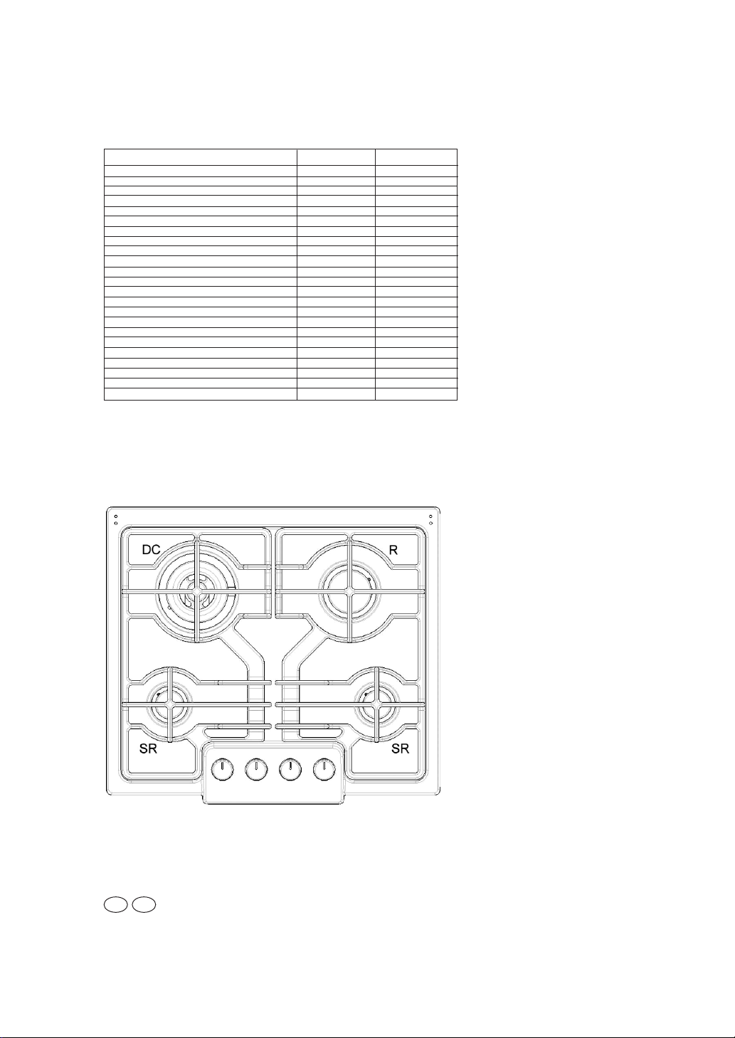
4 gas
-
PL03/PL04
- / yes
1
1
2
1
-
-
-
-
-
8,95 kW
649 g/h
3
230/50
-
yes
590x510
C
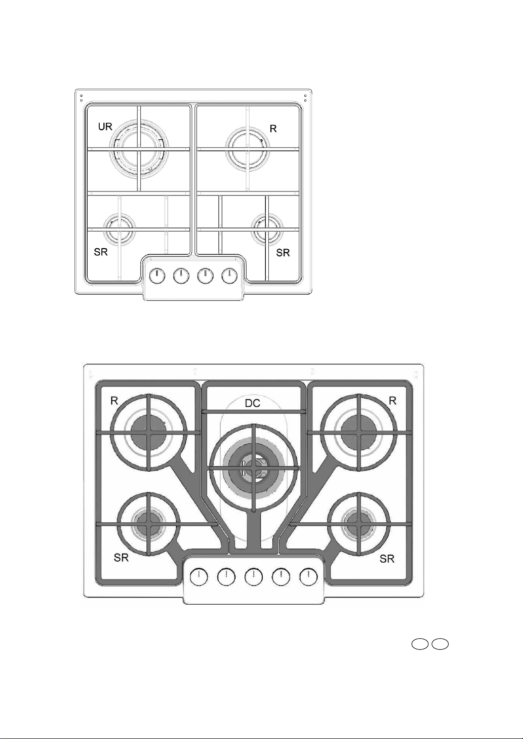
5 gas
-
PL73/PL74
- / yes
1
1
2
2
-
-
-
-
-
11,6kW
842 g/h
3
230/50
-
yes
745x510
DC ø 110 mm
UR ø 110 mm
SR ø 51 mm
R ø 71 mm
2
B
C
GBIE
3
INSTRUCTIONS FOR THE INSTALLER
INSTALLATION
The Purchaser is responsible for the installation of the hob. The Manufacturer does not
accept any responsibility for any damage or loss resulting from incorrect installation,
and as such this will not covered by the Manufacturer’s Guarantee.
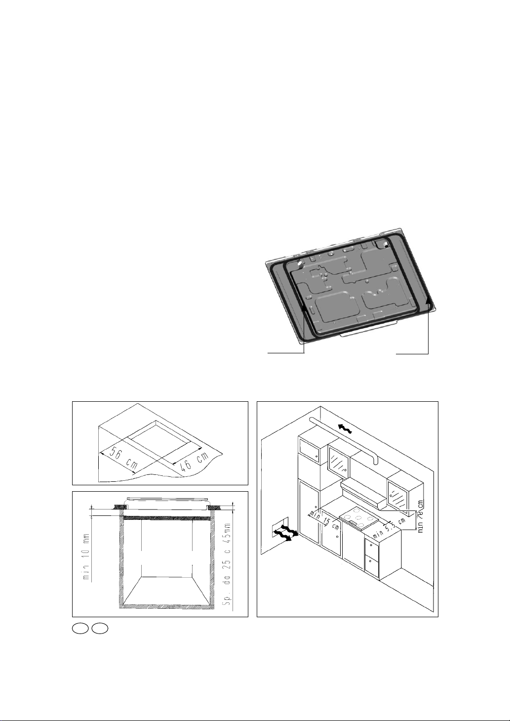
The hob may be installed in any worktop which is heat resistant to a temperature of
100° C, and has a thickness of 25 - 45 mm. The dimensions of the insert to be cut out
of the worktop are in shown in Fig. 1.
If the Hob is fitted next to a cabinet on either side, the distance between the Hob and the
cabinet must be at least 15 cm (see Fig. 2); while the distance between the hob and the
rear wall must be at least 5,5 cm.
The distance between the hob and any
other unit or appliance above it (e.g. An extractor hood) must be no less than 70 cm
(fig.2).
When there is an accessible space between
the built-in hob and the cavity below, a dividing wall made of insulating material should
be inserted (wood or a similar material).
The wall should be at least 10 mm away from
bottom of the drawer. (fig. 3)
Important - The diagram below shows
how the sealant should be applied.
The Hob unit is fitted by attaching the Fixing Clamps supplied, using the holes at the base
of the unit.
Fig. 1
Fig. 2
Fig. 3
accessible space
GB IE
Plan 60 Plan 75
 Loading...