


Hobart TWII Installation Manual

TURBOWASH
TM
. . . Pot and Pan Sink
MODEL
TWII ML-110971
701 S. RIDGE AVENUE
TROY, OHIO 45374-0001
937 332-3000
www.hobartcorp.com
FORM 34504 Rev. B (June 2002)
Installation, Operation, and Care of
TM
TurboWash
Pot and Pan Sink
SAVE THESE INSTRUCTIONS
GENERAL
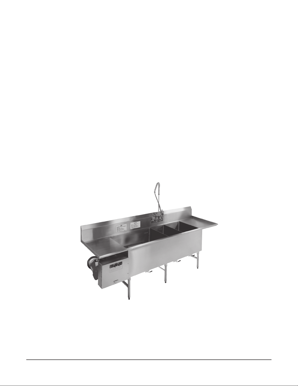
The TurboWash pot and pan sink is the scullery manager's dream. Soiled pots, pans and utensils can
be cleaned in swirling hot water for as long as necessary until soil-adhesion is eliminated. Significantly
less manual effort is required on difficult to clean items. Once washed, the pots, pans and utensils can
be moved to the optional rinse and sanitizer sinks.
• The wash pump motor is rated 2 H.P. and has permanently sealed bearings.
• Sinks can be specified for left-to-right or right-to-left wash/rinse/sanitize flow.
• A scrapper sink is optional between soiled end and wash sink and may be equipped with or
without disposer.
• The AutoFill option provides an automatic timed initial fill for the wash sink.
• Wash Tank Pump Auto Shutoff and Wash Tank Heater are optional.
• The utensil basket accessory allows small items to be washed in the wash sink.
Nominal Dimensions
Front-to-back 34" overall. Sink depth 18"; to water level mark 14". Sink front-to-back 28". Counter
height 34". Height to counter rim 36"; to top of backsplash 45". Optional end styles (hemmed, rolled,
end splash, or dishwasher connection) add incrementally to the overall length. See table, next page.
© HOBART CORPORATION, 1997
– 2 –
sehcnInishtgneLnoitceSelbaliavA
DNEDELIOS
EGDEEGDE
EGDEEGDE
EGDE
"0=demmeH"0"0"03"0"0"0"0=demmeH
1
1=delloR
/2""21resopsido/w"02"23"51"5.81"211=delloR
=hsalpSdnE
1
2
/2"
rehsawhsiD
noitcennoC
muminim"63
DNEDELIOS
DRAOBNIARDDRAOBNIARD
DRAOBNIARDDRAOBNIARD
DRAOBNIARD
)lanoitpO()lanoitpO(
)lanoitpO()lanoitpO(
)lanoitpO(
"02resopsido/w"63"63"81"02"5.812=hsalpSdnE
"42resopsidhtiw"63"24"02"42"42
"03"84"42"03"03
"63"45"03"63"63
"24"06"63"24
"84 "84
"45 "45
"06 "06
REPPARCS
KNISKNIS
KNISKNIS
KNIS
)lanoitpO()lanoitpO(
)lanoitpO()lanoitpO(
)lanoitpO(
KNISHSAW
)dradnatS()dradnatS(
)dradnatS()dradnatS(
)dradnatS(
KNISESNIR
)lanoitpO()lanoitpO(
)lanoitpO()lanoitpO(
)lanoitpO(
KNISREZITINAS
)lanoitpO()lanoitpO(
)lanoitpO()lanoitpO(
)lanoitpO(
DNENAELC
DRAOBNIARDDRAOBNIARD
DRAOBNIARDDRAOBNIARD
DRAOBNIARD
)lanoitpO()lanoitpO(
)lanoitpO()lanoitpO(
)lanoitpO(
DNENAELC
EGDEEGDE
EGDEEGDE
EGDE
1
/2"
1
/2"
rehsawhsiD
noitcennoC
muminim"02
INSTALLATION
UNPACKING
Immediately after unpacking, check for possible shipping damage. If the TurboWash is found to be
damaged, save the packaging material and contact the carrier within 15 days of delivery.
Prior to installation, verify that the electrical service agrees with the specifications on the data plate(s).
ASSEMBLY
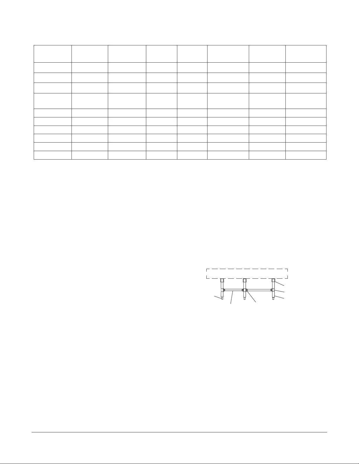
Assemble the H-frame leg sets into the front-rear
leg sockets and tighten the set screws. Fill set
screw heads with silicone sealant (NSF approved).
Allow space for the drain connection and assemble
the frame crossmembers between the rear legs
5
using clamps and
¦16"-18 Screws, Washers,
Lockwashers and Nuts, provided (Fig. 1).
Leveling Foot
TURBOWASH SINK
Frame Crossmember
Middle-Clamp - Bolts
Fig. 1
Leg Socket - Set Screw
End-Clamp - Bolt
Rear Leg
Location
Provide necessary space for proper operation of the TurboWash, including faucet head clearance and
turning diameter so each sink can be filled. Place the TurboWash so it does not interfere with the
operation of other equipment in the area. Place the TurboWash backsplash several inches from the
wall to allow room for leveling.
Leveling
Turn feet in or out to level the unit front-to-back and side-to-side. Slide the TurboWash flush against
the wall so the backsplash can be sealed with silicone sealant.
– 3 –

PLUMBING CONNECTIONS
WARNING: PLUMBING CONNECTIONS MUST COMPLY WITH APPLICABLE SANITARY, SAFETY,
AND PLUMBING CODES.
Drains
Drains underneath the TurboWash should be properly connected to a suitable drain (use 2" dia. pipe).
Recommended drain height is 10 inches above finished floor.
If a grease trap is required by code, it should have a minimum flow capacity of 42 gallons per minute.
Hot Water Connections
Hot water should be connected as required (temperature range 120 – 140°F). Total water hardness
of 4 – 6 grains per gallon is recommended.
Cold Water Connections
Cold water should be connected as required (temperature range 45 – 80°F). Total water hardness of
4 – 6 grains per gallon is recommended.
PLUMBING FITTINGS and Other Options
Temperature mix is provided by faucet(s), optional. Pre-rinse spray is optional. Manual, twist-handleoperated drains (optional) with- or without-overflow (optional) can be provided for installation on each
wash, rinse, and sanitizer sink. A free-flow drain (optional) is available for the scrapper sink when it
is not equipped with a disposer. A wash sink sump with strainer basket is optional — when so equipped,
the recommended drain height is 7 inches above finished floor. A wash sink separater is optional when
the wash sink is at least 42 inches long. Dishwasher connectability (optional) requires a drainboard
with minimum length of 36 inches at the soiled end or 20 inches at the clean end. Over-shelves
(optional) can be installed on the wall above the sink. Under-shelves (optional) can be provided for
installation on frame crossmembers underneath clean-end drainboards that are at least 30 inches long.
When supplied by others, all plumbing fittings and pipes must be copper, stainless steel or brass. When
auto-fill option is used with plumbing supplied by others, an ASSE-certified vacuum breaker must be
installed in accordance with local plumbing codes.
ELECTRICAL CONNECTION
WARNING: ELECTRICAL AND GROUNDING CONNECTIONS MUST COMPLY WITH THE
APPLICABLE PORTIONS OF THE NATIONAL ELECTRICAL CODE AND/OR OTHER LOCAL
ELECTRICAL CODES.
WARNING: DISCONNECT THE ELECTRICAL POWER TO THE MACHINE AND FOLLOW
LOCKOUT/TAGOUT PROCEDURES.
WARNING: IF MORE THAN ONE ELECTRICAL SUPPLY CONNECTION IS PRESENT, ALL SUCH
CONNECTIONS MUST BE DISCONNECTED BEFORE SERVICING.
– 4 –
 Loading...