


|
|
|
|
|
For More Precise Control |
For General Purpose Use |
|
||
 Hitachi Industrial Equipment Systems Co.,Ltd.

Series |
S |
700 |
|
J |
|
Line up |
|
For More Precise Control
High starting Torque,
Powerful Drive and easy setting
High starting Torque
Improved Sensorless Vector Control and Auto Tuning produce high starting torque of 200% or more at 0.3Hz.*1 Easy setup of motor constants
Ideal for applications which need high torque, such as cranes, extruders and lifts.
|
|
Motor Torque vs. Speed |
|
|||||
|
200 |
|
|
|
|
|
|
|
0.3Hz |
|
|
|
|
|
|
||
[%] |
100 |
|
|
|
|
|
|
|
0 |
|
|
|
|
|
|
||
Torque |
300 |
600 |
900 |
1200 |
1500 |
1800 |
||
-100 |
||||||||
|
|
|
|
|
|
|||
-200 |
|
|
|
|
|
|
||
|
|
|
|
|
|
|
||
|
|
|
Speed (min-1) |
|
|
|||
*1 Starting torque |
|
|
|
|
|
|||
Series |
|
Applicable motor |
|
Starting torque |
||||
SJ700 |
|
0.4 to 55kW |
|
|
0.3Hz/200% |
|||
|
75 to 132kW |
|
|
0.3Hz/180% |
||||
|
|
185 to 400kW |
|
|
0.3Hz/150% |
|||
SJ700B |
11 to 75kW |
|
|
0.5Hz/150% |
||||
90 to 160kW |
|
|
0.5Hz/120% |
|||||
|
|
|
|
|||||
Possible with SJ700 Series
Hitachi exclusive
0Hz Domain sensorless vector control *) 

Develops 150%(SJ700B:120%)*2 torque at 0Hz speed reference Ideal for cranes and other applications
that require high torque at starting.
*2 when inverter is one frame size larger than motor.
Position Control Function*)
The SJ700, with optional feedback board installed, together with an encoder-equipped motor can perform position control. For many applications, suitable performance can be achieved at a lower cost than servo systems.
Based on your four motion parameters (position command, speed command, acceleration time and deceleration time), the SJ700 will move an object from original position A to target position B.
After the movement, the inverter keeps servo lock status.
SJ700B
For General Purpose Use
Trip avoidance function
Over current &
voltage suppress function
Higher internal calculation speed improves current control performance.
Over-current suppress and Over-voltage suppress functions avoid inverter trip during acceleration and deceleration.
Frequency |
OC-Trip |
Motor current |
Over-current suppress OFF |
Impact load |
Suppresses over current and continues running |
Over-current suppress ON |
DC Bus AVR Function
During Deceleration
The SJ700 controls deceleration time so that the DC bus voltage does not exceed the over-voltage trip level, providing trip-less operation during deceleration.
Motor current |
Voltage of the |
main circuit DC |
Output frequency |
*) Derating is applied for SJ700B. Please consult technician at Hitachi or its distributor before use.
1

High performance, powerful functions, yet user friendly.
Programming [EzSQ: Easy Sequence] function
Inverter control by Built-in Programming function
Sequence operation is realized by downloading to an inverter a program created with Hitachi's EzSQ software.
Tailor inverter operation to meet changing process requirements, and replace separate PLCs in some cases. By simplifying or eliminating external hardware, signficant cost savings can be achieved.
Password function is incorporated to provide security for proprietary program data against loss or unauthorized modification.
Typical Example - Replacing External Relay Circuit |
||||
Standard Inverter |
SJ700 Using EzSQ |
|||
PB1 |
PB2 |
RY1 |
|
|
|
T2 |
|
|
|
RY1 |
|
RYA |
|
|
|
|
T1 |
|
|
PB2 |
PB1 |
|
EzSQ |
|
|
T1 |
RY2 |
Programming |
|
|
|
|
|
|
RY2 |
|
RYB |
|
|
|
T2 |
|
Programming Window |
|
Operation |
|
|||
circuit |
|
|
Download |
|
|
|
|
||
|
|
|
PB1 |
1 |
|
|
|
|
|
RYA |
FW |
|
PB2 |
2 |
RYB |
8 |
|
||
|
|
CM1 |
||
|
CM1 |
|
|
|
|
|
|
|
|
|
Item |
|
Description |
|
||
|
Language type |
BASIC Like |
|
|
|
|
Spec |
Supported Device |
Windows(DOS/V)OS:Windows2000, WindowsXP) |
||||
Memory area |
1,024 steps or 6k byte |
|
||||
Language |
(Smaller of these)Program is stored in internal of inverter. |
|||||
|
||||||
Programming |
Editor(Windows), Display(Windows) |
|
||||
environment |
Grammar check(Windows) |
|
||||
Program download/upload, All clear |
|
|||||
|
|
|
||||
|
Executable format |
Interpreter 2.0ms/command (Sub routine supported. 8 nested) |
||||
|
|
|
Contact signal/Open collector signal input |
|||
|
|
External digital |
(Internal DC24V power supply available) |
|||
|
|
Program RUN |
|
FW terminal is reserved |
||
|
|
contact input |
command |
|
|
|
|
External input |
|
General-purpose |
|
Maximum of 8 point(X(00)-X(07)) |
|
function |
|
|
input |
|
|
|
|
External analog |
XA(0) : 0-10V (O terminal) |
||||
|
XA(1) : 4-20mA (OI terminal) |
|||||
I/O |
|
input |
||||
|
XA(2) : 0-10V (O2 terminal) |
|||||
|
|
|
||||
|
|
General-purpose |
Maximum of 8 point(Y(00)-Y(05)) |
|||
|
|
output terminal |
|
|
|
|
|
External output |
External analog |
YA(0) : Setup for FM terminal is possible. |
|||
|
YA(1) : Setup for AM terminal is possible. |
|||||
|
|
output |
|
|
|
|
|
|
YA(2) : Setup for AMI terminal is possible. |
||||
|
|
Programmable flow control <Loop, Unconditional jump, conditional jump, |
||||
|
|
Time control, Sub routine, Others> |
|
|||
|
Command |
Operation command <+,-,,*, /, substitution, mod, abs> |
||||
|
I/O control(Bit input, Word input, Bit output, Word output) |
|||||
|
|
|||||
|
|
Timer control <on delay, off delay> |
|
|||
|
|
Inverter parameter setting |
|
|||
|
|
User |
U(00)-U(31)/32 point |
|||
|
|
Timer |
UL(00)-UL(07)/8 point |
|||
word |
|
Set frequency |
SET-Freq |
|
||
|
Acceleration time |
ACCEL |
|
|||
|
|
|
||||
Reserved |
|
Deceleration time |
DECEL |
|
||
|
Monitor |
Output voltage, Power, Cumulative RUN time, |
||||
|
|
|
Output frequency, Output current, Rotative direction, |
|||
|
|
|
PID feedback, Converted frequency, Output torque, |
|||
|
Variable |
|
Cumulative power-on time, trip |
|||
|
|
General-purpose |
X(00)-X(07)/8 point |
|||
|
|
input contact |
|
|
|
|
|
|
General-purpose |
Y(00)-Y(05)/6 point(1 point is relay output) |
|||
|
|
output contact |
|
|
|
|
|
|
Internal user |
UB(00)-UB(07)/8 point |
|||
|
|
Internal timer |
TD(0)-TD(7)/8 point |
|||
|
|
contact |
||||
|
|
|
|
|
||
|
|
Inverter input |
In a remote operator display code. |
|||
|
|
and output |
||||
|
|
|
|
|
|
|
*Windows® is a registered trademark of Microsoft Corporation.U.S.A and other countries.
EMC Filter & Brake circuit integrated as Standard
Built-in EMC Filter up to 150kW*
Cost and space reduction compared with external EMC Filter. Reduces electromagnetic noise.
Meets EN61800-3 2nd-Environment
*SJ700: European Version and Japanese Version does not have 150kW SJ700B: All models
Brake circuit up to 22kW*
Cost and Space reduction compared with external Braking Controller.
*SJ700B: Up to 30kW
Level [db]
|
Example (SJ700-110HFEF2) |
|
||||
130 |
|
|
|
|
|
|
120 |
|
|
EN61800-3 2nd Envinment |
|||
110 |
|
|
[C3]QP Limit Level |
|
||
100 |
|
|
|
|
|
|
90 |
|
|
|
|
|
|
80 |
|
|
|
|
|
|
70 |
|
|
|
|
|
|
60 |
|
|
|
|
|
|
50 |
|
|
|
|
|
|
40 |
|
|
|
|
|
|
30 |
|
|
|
|
|
|
20 |
|
|
|
|
|
|
10 |
|
|
|
|
|
|
0 |
500k |
1M |
2M |
5M |
7M 10M |
20M 30M |
150k200k |
||||||
|
|
Frequency |
[Hz] |
|
QP: Quasi Peak |
|
|
|
|
|
|
|
|
2
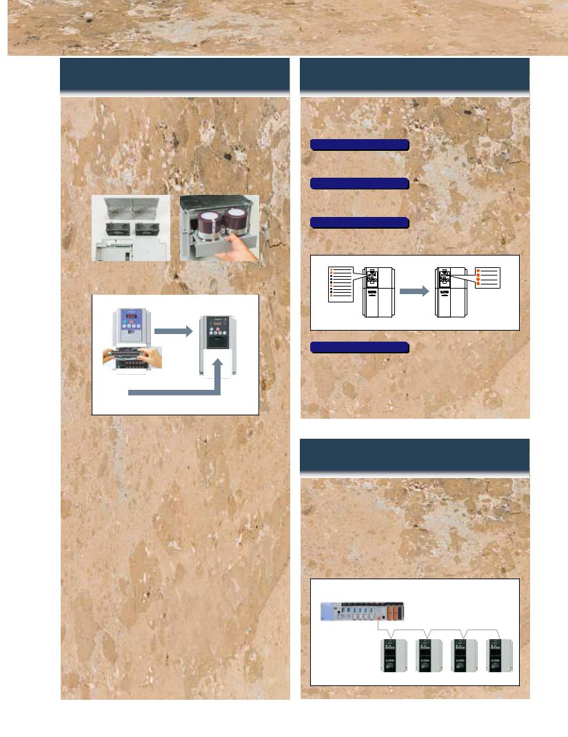
Ease of Maintenance
Easy-removable construction for maintenance
Field replacement of cooling fan(s) and DC bus capacitors can be accomplished in a fraction of the time.
Using Logic terminal move to SJ700 without wiring change. Read SJ300 Parameter by SRW remote operator and write them in to SJ700
|
|
|
|
|
|
|
|
Easy-removable |
|
|
|
Easy-removable |
|||
Cooling Fan |
|
|
|
DC bus Capacitors |
|||
|
|
|
|
|
|
|
(SJ700: above 15kW |
|
|
|
|
|
|
|
SJ700B: above 18.5kW) |
|
SJ300series |
|
|
|
SJ700series |
||
|
|
|
|
Parameter |
|||
|
|
|
|
read write |
|||
|
|
|
|
|
|
|
|
|
|
|
|
|
|
|
|
|
|
|
|
|
|
|
|
Removable Control circuit terminals (Move to SJ700 without rewiring)
|
*1 Control circuit terminals comparison table |
|
|
|
|
Series |
Input terminals |
Output terminals |
|
|
SJ700 |
9terminals |
5terminals |
|
|
SJ700B |
|
||
|
(Intelligent 8terminals,FW) |
(Open collector outputs) |
|
|
|
SJ300 |
|
||
|
|
|
|
|
|
L300P |
6terminals |
2terminals |
|
|
(Intelligent 5terminals,FW) |
(Relay outputs) |
|
|
|
|
|
|
|
|
|
|
|
|
Long life time components & Life time warning function
Long life time components
Design lifetime 10 Years or more for DC bus capacitors & Cooling Fan.
Cooling Fan ON/OFF control function for longer fan life.
*Ambient temperature: Average 40 deg C (SJ700B: 30 deg C) (no corrosive gases, oil mist or dust)
Design lifetime is calculated, and not guaranteed.
Life time warning function
Perform preventive maintenance before a failure occurs using the Lifetime Warning function.
DC bus capacitor, cooling fan, heat sink temperature and motor temperature can be monitored in order to replace components prior to failure.
Easy Operation
User selection of Displayed Parameters
Data comparison function
Allows display of only parameters changed from default.
User selected function
Display of up to 12 User Defined Parameters U001 to U012.
Basic mode (default)
Basic display mode for commonly used parameters.
Basic
mode
Indication only

 Basic Parameter Chose Basic
Parameter
Other Functions
-The direct input of function code selection is possible rather than scrolling through the list.
-Holding down the function key for 3 seconds, causes the display to jump to output frequency monitor (d001) mode from any menu location.
Network compatibility
A serial RS-485 Modbus-RTU port is standard. The SJ700 can communicate with DeviceNet,
PROFIBUS-DP, and other networks with communication options.
-DeviceNet is a trade mark of Open DeviceNet Vender Association, Inc. -PROFIBUS-DP is a registered trade mark of PROFIBUS Nutzer Organization
Simple & Low cost wiring, Ease of installation and replacement
3

Global standards
Conformity to global standards
CE, UL, c-UL, C-Tick approvals.
Logic input & output Terminal apply sink & source logic
Wide Input power voltage range
Input voltage 240V for 200V class and 480V for 400V class as standard.
Environmental Friendliness
Micro Surge Voltage suppress function
Hitachi original PWM control method limits motor terminal voltage to less than two of inverter DC bus voltage. Lower than Hitachi motor Max. insulation voltage (1,250V)
(During regeneration, the motor terminal voltage may exceed the motor maximum insulation voltage(1,250V))
Motor terminal voltage
1,250V
E=650V, cable=100m
EU RoHS compliant
EU RoHS compliant (except solder in power module)
Improvement of environment
Varnish coating of internal PC board & plating of main circuit copper bus bar are standard.
Versatile Functions
Instantaneous Power Failure Disregard Function
The SJ700 ignores instantaneous power failure when power fluctuation happens frequently, as long as DC bus voltage remains higher than under-voltage trip level.
Emergency stop
Shuts down the inverter by hardware, bypassing
the CPU, to achieve a reliable, emergency stop function.
Intelligent input terminal and output terminal ON/OFF delay function
Helps simplify external circuits.
Active frequency matching function
Motor frequency match restart function operates effectively even without motor residual voltage.
Controlled deceleration and stop on power loss
Analog Input Disconnection Detection Function
The SJ700 (SJ700B) outputs a disconnection signal when frequency command through analog input is lost.
Acceleration/Deceleration curve functions
The curve shape (five kinds, such as S-curve, etc.) can be chosen according to the application requirements.
Analog Command Holding Function (AHD)
Output frequency can be changed with UP/DOWN Function, or with an analog signal as reference value. The set frequency at power shutdown can be saved, too.
Pulse train input function
Pulse train input for Frequency reference or PID
feed back signal, with SJ-FB (speed feed back card option).
Integrated Input Electric Power monitor
Input electric power (kW) and Integrated input electric power for monitoring energy saving.
Automatic Carrier Frequency Adjustment Function
The SJ700 detects motor current and automatically reduces carrier frequency according to the current.
The resolution of analog outputs (voltage, current) is improved to 10 bits.
4

STANDARD SPECIFICATIONS
SJ700 Series
 3-phase 200V class
Model SJ700- |
|
|
JP Version |
004LFF2 |
007LFF2 |
015LFF2 |
022LFF2 |
037LFF2 |
055LFF2 |
075LFF2 |
110LFF2 |
150LFF2 |
185LFF2 |
220LFF2 |
300LFF2 |
370LFF2 |
450LFF2 |
550LFF2 |
|
|
|
US Version |
004LFUF2 |
007LFUF2 |
015LFUF2 |
022LFUF2 |
037LFUF2 |
055LFUF2 |
075LFUF2 |
110LFUF2 |
150LFUF2 |
185LFUF2 |
220LFUF2 |
300LFUF2 |
370LFUF2 |
450LFUF2 |
550LFUF2 |
||
|
|
|
|
||||||||||||||||
Enclosure (*1) |
|
|
|
|
|
|
|
|
|
|
IP20 |
|
|
|
|
|
|
|
|
Applicable motor (4-pole, kW(HP)) (*2) |
|
0.4(1/2) |
0.75(1) |
1.5(2) |
2.2(3) |
3.7(5) |
5.5(7.5) |
7.5(10) |
11(15) |
15(20) |
18.5(25) |
22(30) |
30(40) |
37(50) |
45(60) |
55(75) |
|||
|
|
Rated capacity |
|
200V |
1.0 |
1.7 |
2.6 |
3.6 |
5.7 |
8.3 |
11.0 |
15.9 |
22.1 |
26.3 |
32.9 |
41.9 |
50.2 |
63.0 |
76.2 |
|
|
(kVA) |
|
240V |
1.2 |
2.0 |
3.1 |
4.3 |
6.8 |
9.9 |
13.3 |
19.1 |
26.6 |
31.5 |
39.4 |
50.3 |
60.2 |
75.6 |
91.4 |
Output Ratings |
Rated output current (A) |
3 |
5 |
7.5 |
10.5 |
16.5 |
24 |
32 |
46 |
64 |
76 |
95 |
121 |
145 |
182 |
220 |
|||
|
|
Overload capacity(output current) |
|
|
|
|
|
|
150%,60sec., 200%,3sec. |
|
|
|
|
|
|
||||
|
|
Rated output voltage (*3) |
|
|
|
3-phase (3-wire) 200 to 240V (corresponding to input voltage) |
|
|
|
|
|||||||||
Input Rating |
|
Rated input voltage (V) |
|
|
|
|
3-phase 200 to 240V+10%, -15%, 50/60Hz±5% |
|
|
|
|
|
|||||||
|
Rated input current (A) |
3.3 |
5.5 |
8.3 |
12 |
18 |
26 |
35 |
51 |
70 |
84 |
105 |
133 |
160 |
200 |
242 |
|||
|
|
||||||||||||||||||
Braking |
|
Dynamic braking (Short-time) (*4) |
|
|
|
Built-in BRD circuit (optional resistor) |
|
|
|
External dynamic braking unit (option) |
|||||||||
|
Minimum value of resistor (Ω) |
50 |
50 |
35 |
35 |
35 |
16 |
10 |
10 |
7.5 |
7.5 |
5 |
|
- |
|
||||
|
|
|
|
||||||||||||||||
Vibration (*5) |
|
|
|
|
|
|
|
5.9m/s2(0.6G), 10-55Hz |
|
|
|
|
2.9m/s2(0.3G), 10-55Hz |
||||||
EMC filter |
|
|
|
|
|
|
|
|
Built-in (EN61800-3 category C3) |
|
|
|
|
|
|||||
Zero-phase Reactor |
|
|
|
|
|
|
|
|
Built-in |
|
|
|
|
|
|
|
|||
Weight [kg] (lbs.) |
|
|
|
3.5(7.7) |
3.5(7.7) |
3.5(7.7) |
3.5(7.7) |
3.5(7.7) |
6(13.2) |
6(13.2) |
6(13.2) |
14(30.8) |
14(30.8) |
14(30.8) |
22(48.4) |
30(66) |
30(66) |
43(94.6) |
|
 3-phase 400V class
|
|
|
JP Version |
007HFF2 |
015HFF2 |
022HFF2 |
037HFF2 |
055HFF2 |
075HFF2 |
110HFF2 |
150HFF2 |
185HFF2 |
220HFF2 |
300HFF2 |
370HFF2 |
450HFF2 |
550HFF2 |
|
Model SJ700- |
|
European Version |
007HFEF2 |
015HFEF2 |
022HFEF2 |
040HFEF2 |
055HFEF2 |
075HFEF2 |
110HFEF2 |
150HFEF2 |
185HFEF2 |
220HFEF2 |
300HFEF2 |
370HFEF2 |
450HFEF2 |
550HFEF2 |
||
|
|
|
US Version |
007HFUF2 |
015HFUF2 |
022HFUF2 |
040HFUF2 |
055HFUF2 |
075HFUF2 |
110HFUF2 |
150HFUF2 |
185HFUF2 |
220HFUF2 |
300HFUF2 |
370HFUF2 |
450HFUF2 |
550HFUF2 |
|
Enclosure (*1) |
|
|
|
|
|
|
|
|
IP20 |
|
|
|
|
|
|
|
||
Applicable motor (4-pole, kW(HP)) (*2) |
0.75(1) |
1.5(2) |
2.2(3) |
4.0(5)3.7(5) |
5.5(7.5) |
7.5(10) |
11(15) |
15(20) |
18.5(25) |
22(30) |
30(40) |
37(50) |
|
45(60) |
55(75) |
|||
|
|
Rated capacity |
400V |
1.7 |
2.6 |
3.6 |
6.2 |
9.7 |
13.1 |
17.3 |
22.1 |
26.3 |
33.2 |
40.1 |
51.9 |
|
63.0 |
77.6 |
|
|
(kVA) |
480V |
2.0 |
3.1 |
4.4 |
7.4 |
11.6 |
15.8 |
20.7 |
26.6 |
31.5 |
39.9 |
48.2 |
62.3 |
|
75.6 |
93.1 |
Output Ratings |
|
Rated output current (A) |
2.5 |
3.8 |
5.3 |
9.0 |
14 |
19 |
25 |
32 |
38 |
48 |
58 |
75 |
|
91 |
112 |
|
|
|
Overload capacity(output current) |
|
|
|
|
|
150%,60sec., 200%,3sec. |
|
|
|
|
|
|
||||
|
|
Rated output voltage (*3) |
|
|
|
3-phase (3-wire) 380 to 480V (corresponding to input voltage) |
|
|
|
|
|
|||||||
Input Rating |
|
Rated input voltage (V) |
|
|
|
|
3-phase 380 to 480V +10%, -15%, 50/60Hz±5% |
|
|
|
|
|
||||||
|
Rated input current (A) |
2.8 |
4.2 |
5.8 |
9.9 |
17 |
23 |
30 |
35 |
42 |
53 |
64 |
83 |
|
100 |
123 |
||
|
|
|
||||||||||||||||
Braking |
|
Dynamic braking (Short-time) (*4) |
|
|
|
Built-in BRD circuit (optional resistor) |
|
|
|
External dynamic braking unit (option) |
||||||||
|
Minimum value of resistor (Ω) |
100 |
100 |
100 |
70 |
70 |
35 |
35 |
24 |
24 |
20 |
|
|
- |
|
|||
|
|
|
|
|
||||||||||||||
Vibration (*5) |
|
|
|
|
|
5.9m/s2(0.6G), 10-55Hz |
|
|
|
2.9m/s2(0.3G), 10-55Hz |
||||||||
EMC filter |
|
|
|
|
|
|
|
Built-in (EN61800-3 category C3) |
|
|
|
|
|
|
||||
Zero-phase Reactor |
|
|
|
|
|
|
|
Built-in |
|
|
|
|
|
|
|
|||
Weight [kg] (lbs.) |
|
|
3.5(7.7) |
3.5(7.7) |
3.5(7.7) |
3.5(7.7) |
6(13.2) |
6(13.2) |
6(13.2) |
14(30.8) |
14(30.8) |
14(30.8) |
22(48.4) |
30(66) |
|
30(66) |
30(66) |
|
|
|
|
|
|
|
|
|
|
|
|
|
|
|
|
|
|
|
|
|
|
|
European Version |
750HFEF2 |
900HFEF2 |
1100HFEF2 |
1320HFEF2 |
1850HFE2 |
2200HFE2 |
3150HFE2 |
4000HFE2 |
|
|
|
|
|
|
|
Model SJ700- |
|
US Version |
750HFUF2 |
900HFUF2 |
1100HFUF2 |
1500HFUF2 |
1850HFU2 |
2200HFU2 |
3150HFU2 |
4000HFU2 |
|
|
|
|
|
|
|
|
|
|
|
JP Version |
750HFF2 |
900HFF2 |
1100HFF2 |
1320HFF2 |
1850HF2 |
2200HF2 |
3150HF2 |
4000HF2 |
|
|
|
|
|
|
|
Enclosure (*1) |
|
|
|
|
|
IP00 |
|
|
|
|
|
|
|
|
|
|
||
Applicable motor (4-pole, kW(HP)) (*2) |
75(100) |
90(125) |
110(150) |
132(175) |
185(250) |
220(300) |
315(400) |
400(550) |
|
|
|
|
|
|
|
|||
|
|
Rated capacity |
400V |
103.2 |
121.9 |
150.3 |
180.1 |
256 |
305 |
416 |
554 |
|
|
|
|
|
|
|
|
|
(kVA) |
480V |
123.8 |
146.3 |
180.4 |
216.1 |
308 |
366 |
499 |
665 |
|
|
|
|
|
|
|
Output Ratings |
|
Rated output current (A) |
149 |
176 |
217 |
260 |
370 |
440 |
600 |
800 |
|
|
|
|
|
|
|
|
|
|
Overload capacity(output current) |
150%,60sec., 200%,0.5sec. |
150%,60sec., 180%,0.5sec. |
|
|
|
|
|
|
|
|||||||
|
|
Rated output voltage (*3) |
3-phase (3-wire) 380 to 480V (corresponding to input voltage) |
|
|
|
|
|
|
|
||||||||
Input Rating |
|
Rated input voltage (V) |
|
3-phase 380 to 480V +10%, -15%, 50/60Hz±5% |
|
|
|
|
|
|
|
|
||||||
|
Rated input current (A) |
164 |
194 |
239 |
286 |
389 |
455 |
630 |
840 |
|
|
|
|
|
|
|
||
|
|
|
|
|
|
|
|
|
||||||||||
Braking |
|
Dynamic braking (Short-time) (*4) |
|
|
External dynamic braking unit (option) |
|
|
|
|
|
|
|
|
|
||||
|
Minimum value of resistor (Ω) |
|
|
|
- |
|
|
|
|
|
|
|
|
|
|
|||
|
|
|
|
|
|
|
|
|
|
|
|
|
|
|
||||
Vibration (*5) |
|
|
2.9m/s2(0.3G), 10-55Hz |
1.96m/s2(0.2G), 10-55Hz |
|
|
|
|
|
|
|
|||||||
EMC filter |
|
|
Built-in (EN61800-3 category C3) |
|
External Option |
|
|
|
|
|
|
|
|
|||||
Zero-phase Reactor |
|
|
Built-in |
|
|
External Option |
|
|
|
|
|
|
|
|
||||
Weight [kg] (lbs.) |
|
|
60(132) |
60(132) |
80(176) |
80(176) |
140(308) |
145(319) |
210(462) |
360(792) |
|
|
|
|
|
|
|
|
5

STANDARD SPECIFICATIONS
SJ700B Series
 3-phase 400V class
Model SJ700B- |
|
|
|
110HFF |
150HFF |
185HFF |
220HFF |
300HFF |
370HFF |
450HFF |
550HFF |
750HFF |
|
900HFF |
1100HFF |
1320HFF |
1600HFF |
Enclosure (*1) |
|
|
|
|
|
|
|
IP20 |
|
|
|
|
|
|
IP00 |
|
|
Applicable motor (4-pole, kW(HP)) (*2) |
|
11(15) |
15(20) |
18.5(25) |
22(30) |
30(40) |
37(50) |
45(60) |
55(75) |
75(100) |
|
90(125) |
110(150) |
132(150) |
160(220) |
||
|
Rated capacity |
|
400V |
15.2 |
20.0 |
25.6 |
29.7 |
39.4 |
48.4 |
58.8 |
72.7 |
93.5 |
|
110.8 |
135.1 |
159.3 |
200.9 |
Output Ratings |
(kVA) |
|
480V |
18.2 |
24.1 |
30.7 |
35.7 |
47.3 |
58.1 |
70.6 |
87.2 |
112.2 |
|
133 |
162.1 |
191.2 |
241.1 |
Rated output current (A) |
22 |
29 |
37 |
43 |
57 |
70 |
85 |
105 |
135 |
|
160 |
195 |
230 |
290 |
|||
|
Overload capacity(output current) |
|
|
|
|
|
|
120%,60sec |
|
|
|
|
|
|
|||
|
Rated output voltage (*3) |
|
|
|
3-phase (3-wire) 380 to 480V (corresponding to input voltage) |
|
|
|
|||||||||
Input Rating |
Rated input voltage (V) |
|
|
|
|
3-phase 380 to 480V +10%, -15%, 50/60Hz±5% |
|
|
|
|
|
||||||
Rated input current (A) |
24 |
32 |
41 |
47 |
63 |
77 |
94 |
116 |
149 |
|
176 |
199 |
253 |
300 |
|||
|
|
||||||||||||||||
Braking |
Dynamic braking (Short-time) (*4) |
Built-in BRD circuit (optional resistor) |
|
|
External dynamic braking unit (option) |
|
|
||||||||||
Minimum value of resistor (Ω) |
35 |
35 |
24 |
24 |
20 |
|
|
|
|
- |
|
|
|
||||
|
|
|
|
|
|
|
|
||||||||||
Vibration (*5) |
|
|
|
|
5.9m/s2(0.6G), 10-55Hz |
|
|
|
2.9m/s2(0.3G), 10-55Hz |
|
|
||||||
EMC filter |
|
|
|
|
|
|
|
|
Built-in (EN61800-3 category C3) |
|
|
|
|
|
|||
Zero-phase Reactor |
|
|
|
|
|
|
|
Built-in |
|
|
|
|
|
|
|
||
Weight (lbs.) |
|
|
|
6(13.2) |
6(13.2) |
14(30.8) |
14(30.8) |
14(30.8) |
22(48.4) |
30(66) |
30(66) |
30(66) |
|
55(121) |
55(121) |
70(154) |
70(154) |
*1: The protection method conforms to JEM 1030.
*2: The applicable motor refers to Hitachi standard 3-phase motor (4-pole).To use other motors, be sure to prevent the rated motor current (50Hz) from exceeding the rated output current of the inverter. *3: The output voltage decreases as the main power supply voltage decreases except for the use of AVR function.
*4: Braking resistor is not integrated in the inverter. Please install optional braking resistor or dynamic braking unit when large braking torque is required. *5: Conforms to the test method specified in JIS C 60068-2-6 : 2010 (IEC 60068-2-6 : 2007).
*6: To operate the motor beyond 50/60Hz, please consult with the motor manufacturer about the maximum allowable rotation speed. *7: Storage temperature refers to the temperature in transportation.
*8: The frequency command is the maximum frequency at 9.8V for input voltage 0 to 10VDC, or at 19.6mA for input current 4 to 20mA. If this characteristic is not satisfactory for your application,contact your Hitachi representative.
Model Name Indication
SJ700 series |
SJ700-055 H F E F 2 |
Series Name 


 Applicable Motor Capacity 004:| 0.4kW(1/2HP)
4000:400kW(500HP)
Power Source L: 3-phase 200V class
H: 3-phase 400V class
F: With keypad
U : US version
E : European version
Note: Japanese version
F: Integrated EMC filter
Version
SJ700B series |
SJ700B-110 H F F |
|||||||||||||||||||
Series Name |
|
|
|
|
|
|
|
|
|
|
|
|
|
|
|
|
|
|
|
|
|
110:| 11kW(15HP) |
|
|
|
|
|
|
|
|
|
|
|
|
|
|
|
||||
Applicable Motor Capacity |
|
|
|
|
|
|
|
|
|
|
|
|
|
|
|
|||||
|
|
|
|
|
|
|
|
|
|
|
|
|
|
|
||||||
|
|
1600:160kW(220HP) |
|
|
|
|
|
|
|
|
||||||||||
Power Source |
H: 3-phase 400V class |
|
|
|
|
|
|
|
|
|
|
|
|
|||||||
|
|
|
|
|
|
|
|
|
|
|
|
|||||||||
|
|
F: With keypad |
|
|
|
|
|
|
|
|
|
|
|
|
|
|||||
|
|
|
|
|
|
|
|
|
|
|
|
|
|
|
||||||
|
|
F: Integrated EMC filter |
|
|
|
|
|
|
|
|
|
|||||||||
|
|
|
|
|
|
|
|
|
|
|
||||||||||
Model Configuration  Available
Applicable Motor kW (HP) |
(1/2) |
(1) |
(2) |
(3) |
(5) |
(5) |
(7.5) |
(7.5) |
(15) |
(20) |
(25) |
(30) |
(40) |
(50) |
(60) |
(75) |
(100) |
(125) |
(150) (175) (200) (220) (250) |
(300) |
(400) |
(550) |
||||
|
0.4 |
0.75 |
1.5 |
2.2 |
3.7 |
4.0 |
5.5 |
7.5 |
11 |
15 |
18.5 |
22 |
30 |
37 |
45 |
55 |
75 |
90 |
110 |
132 |
150 |
160 |
185 |
220 |
315 |
400 |
|
|
|
|
|
|
|
|
|
|
|
|
|
|
|
|
|
|
|
|
|
|
|
|
|
|
|
SJ700
3-phase 200V |
|
LFUF2 |
|
|
|
|
|
|
|
|
|
|
|
|
|
||||
|
|
|
|
|
|
|
|
|
|
|
|
|
|
|
|
|
|
||
LFF2 |
|
|
|
|
|
|
|
||
|
|
|
|
|
|
|
|
||
|
|
|
|
|
|
|
|||
|
|
|
|
|
|
|
|||
3-phase 400V |
|
HFEF2 |
|
|
|
|
|
||
|
|
|
|
|
|||||
|
|
|
|
|
|
|
|||
|
|
|
|
|
|||||
|
HFUF2 |
|
|
|
|
|
|||
|
|
|
|
||||||
|
|
|
|
|
|
|
|||
|
|
|
|
|
|
||||
|
|
HFF2 |
|
|
|
|
|
||
|
|
|
|
|
|
||||
|
|
|
|
|
|
|
|
|
|
SJ700B
3-phase 400V |
|
HFF |
|
|
|
|
|
|
|||
|
|
|
|
|
|
6

SPECIFICATIONS
 General Specifications
|
Items |
|
General Specifications |
||
|
Control method |
|
Line to line sine wave pulse-width modulation (PWM) control |
||
|
Output frequency range (*6) |
0.1-400.0Hz(400kW:0.1-120Hz) |
|||
|
Frequency accuracy |
|
Digital: ±0.01% of the maximum frequency, Analog: ±0.2%(25±10˚C) |
||
|
Frequency resolution |
Digital setting: 0.01Hz, Analog setting: (Maximum frequency)/4,000 (O terminal: 12bit 0-10V, O2 terminal: 12bit -10-+10V) |
|||
|
V/f characteristics |
|
V/f optionally variable (30-400Hz of base frequency), V/f control (constant torque, reduced torque), Sensorless vector control, 0Hz domain sensorless vector |
||
|
|
control, vector control (SJ-FB card option) |
|||
|
|
|
|
||
Control |
Speed fluctuation |
|
±0.5% (sensorless vector control) |
||
|
Acceleration/deceleration time |
0.01-3,600sec. (Linear/curve, accel./decel. selection), Two-stage accel./decel. |
|||
|
|
|
|
SJ700 (Sensorless vector control): 200% at 0.3Hz/ 75kW to 150kW:180% at 0.3Hz,185kW and over:150% at 0.3Hz. |
|
|
Starting Torque |
|
SJ700B (Sensorless vector control): 150% at 0.5Hz/ 90kW and over:120% at 0.5Hz, |
||
|
|
|
|
SJ700 (0Hz domain with motor one frame size down):150% at around 0Hz/ 75kW and over: 130% at around 0Hz. |
|
|
Carrier frequency range |
SJ700: 0.5-15.0kHz(185kW and over:0.5-3.0kHz)/SJ700B: 0.5-12.0kHz(90kW and over:0.5-8.0kHz) |
|||
|
DC braking |
|
Performs at start: under set frequency at deceleration, via an external input (braking force, time, and operating frequency). |
||
|
Frequency |
|
Operator |
Up and Down keys |
|
|
|
External signal*8 |
DC 0-10V, -10-+10V (input impedance 10kΩ), 4-20mA (input impedance 100Ω) |
||
|
setting |
|
|||
|
|
External port |
Setting via RS485 communication |
||
|
|
|
|||
|
Forward /reverse |
|
Operator |
Start/stop commands (forward/reverse switching by parameter setting) |
|
|
|
External signal |
Forward-operation start/stop commands (reverse-operation start/stop possible when relevant commands are assigned to intelligent input terminals)3-wire |
||
|
Start /stop |
|
input possible (when relevant commands are assigned to control circuit terminals) |
||
|
|
|
External port |
Setting via RS485 communication |
|
|
|
|
Terminals |
8 terminals, NO/NC switchable, sink logic/source logic switchable |
|
|
|
|
|
Reverse operation (RV), Multi-speed 1 setting (CF1), Multi-speed 2 setting (CF2), Multi-speed 3 setting (CF3), Multi-speed 4 setting (CF4), Jogging (JG), |
|
|
|
|
|
external DC braking (DB), 2nd motor control (SET), 2-stage acceleration/deceleration (2CH), free-run stop (FRS), external trip (EXT), unattended start |
|
Input signal |
|
|
|
protection (USP), commercial power supply switching (CS), software lock (SFT), analog input switching (AT), 3rd motor control (SET3), reset (RS), starting by |
|
|
|
|
3-wire input (STA), stopping by 3-wire input (STP), forward/reverse switching by 3-wire input (F/R), PID disable (PID), PID integration reset (PIDC), control |
||
|
|
|
|
gain switching (CAS), acceleration by remote control (UP), deceleration by remote control (DWN), data clearance by remote control (UDC), forcible operation |
|
|
Intelligent |
|
|
(OPE), Multi-speed bit 1 (SF1), Multi-speed bit 2 (SF2), Multi-speed bit 3 (SF3), Multi-speed bit 4 (SF4), Multi-speed bit 5 (SF5), Multi-speed bit 6 (SF6), |
|
|
|
Functions |
Multi-speed bit 7 (SF7), overload restriction selection (OLR), torque limit selection (enabling/disabling) (TL), torque limit 1 (TRQ1), torque limit 2 (TRQ2), P/PI |
||
|
input terminals |
|
switching (PPI), braking confirmation (BOK), orientation (ORT), LAD cancellation (LAC), clearance of position deviation (PCLR), permission of 90˚shift phase |
||
|
|
|
|
(STAT), trigger for frequency addition (A145) (ADD), forcible-terminal operation (F-TM), permission of torque command input (ATR), cumulative power |
|
|
|
|
|
clearance (KHC), servo-on (SON), pre-excitation (FOC), general-purpose input 1 (MI1), general-purpose input 2 (MI2), general-purpose input 3 (MI3), |
|
|
|
|
|
general-purpose input 4 (MI4), general-purpose input 5 (MI5), general-purpose input 6 (MI6), general-purpose input 7 (MI7), general-purpose input 8 (MI8), |
|
|
|
|
|
analog command holding (AHD), Multistage position settings selection 1 (CP1), Multistage position settings selection 2 (CP2), Multistage position settings |
|
|
|
|
|
selection 3 (CP3), Zero-return limit function (ORL), Zero-return trigger function (ORG), Forward drive stop (FOT), reverse drive stop (ROT), Speed / position switching |
|
|
|
|
|
(SPD), Pulse counter (PCNT), Pulse counter clear (PCC), Emergency stop (EMR) ,no assignment (no) |
|
|
Thermistor input |
|
1 terminal (PTC characteristics) |
||
|
|
|
Terminals |
5 open-collector output terminals, NO/NC switchable, sink logic/source logic switchable 1 relay (1c-contact) output terminal: NO/NC switchable |
|
|
|
|
|
Running (RUN), constant-speed reached (FA1), set frequency overreached (FA2), overload notice advance signal (1) (OL), output deviation for PID control |
|
|
|
|
|
(OD), alarm signal (AL), set frequency reached (FA3), over-torque (OTQ), instantaneous power failure (IP), undervoltage (UV), torque limited (TRQ), |
|
|
|
|
|
operation time over (RNT), plug-in time over (ONT), thermal alarm signal (THM), brake release (BRK), braking error (BER), 0Hz detection signal (ZS), |
|
|
|
|
|
speed deviation maximum (DSE), positioning completed (POK), set frequency overreached 2 (FA4), set frequency reached 2 (FA5), overload notice |
|
|
Intelligent |
|
|
advance signal (2) (OL2), PID feedback comparison (FBV), communication line disconnection (NDc), logical operation result 1 (LOG1), logical operation |
|
Output signal |
|
Functions |
result 2 (LOG2), logical operation result 3 (LOG3), logical operation result 4 (LOG4), logical operation result 5 (LOG5), logical operation result 6 (LOG6), |
||
output terminals |
|
|
capacitor life warning (WAC)(*11), cooling-fan speed drop (WAF), starting contact signal (FR), heat sink overheat warning (OHF), low-current indication |
||
|
|
|
|
signal (LOC), general-purpose output 1 (M01), general-purpose output 2 (M02), general-purpose output 3 (M03), general-purpose output 4 (M04), |
|
|
|
|
|
general-purpose output 5 (M05), general-purpose output 6 (M06), inverter ready (IRDY), forward rotation (FWR), reverse rotation (RVR), major failure |
|
|
|
|
|
(MJA), window comparator O (WCO), window comparator OI (WCOI), window comparator O2 (WCO2), alarm code 0 to 3 (AC0 to AC3) |
|
|
|
|
Monitor output |
Analog voltage output, analog current output, pulse-string output (e.g., A-F, D-F [n-fold, pulse output only], A, T, V, P) |
|
|
|
|
terminals |
|
|
Monitoring on display |
|
Output frequency, output current, output torque, frequency conversion data, trip history, input/output terminal status, electric power, and others |
|||
|
|
|
|
Free V/f setting (7 breakpoints), frequency upper/lower limit, jump (center) frequency, acceleration/deceleration according to characteristic curve, manual |
|
|
|
|
|
torque boost level/breakpoint, energy-saving operation, analog meter adjustment, start frequency setting, carrier frequency adjustment, electronic thermal |
|
|
|
|
|
function (available also for free setting), external start/end frequency/frequency rate, analog input selection, retry after trip, restart after instantaneous power |
|
Other functions |
|
|
|
failure, output of various signals, starting with reduced voltage, overload restriction, initial-value setting, automatic deceleration at power failure, AVR |
|
|
|
|
|
function, fuzzy acceleration/deceleration, online/offline auto-tuning, high-torque multi-motor operation(*11) (sensorless vector control of two motors by one |
|
|
|
|
|
inverter) |
|
Protective functions |
|
Overcurrent protection, overvoltage protection, undervoltage protection, electronic thermal protection, temperature error protection, instantaneous power |
|||
|
failure protection, phase loss input protection, braking-resistor overload protection, ground-fault current detection at power-on, USP error, external trip, |
||||
|
|
|
|
emergency stop trip, CT error, communication error, option board error, and others |
|
Environmental |
Ambient operating/storage |
-10-50˚C(*9) / -20-65˚C / 20-90%RH (No condensation) |
|||
temperature(*7)/ humidity |
|||||
conditions |
Location |
|
Altitude 1,000m or less, indoors (no corrosive gases or dust) |
||
|
Digital input expansion card |
SJ-DG (4digits BCD, 16bits binary) |
|||
Options |
Feedback expansion card |
SJ-FB (vector control loop speed sensor) |
|||
Network interface card |
SJ-DN2(DeviceNet(TM)), SJ-PBT(PROFIBUS) |
||||
|
|||||
|
Others |
|
EMI filters, input/output reactors, radio noize filters, braking resistors, braking units, LCR filter, communication cables |
||
*1: The protection method conforms to JEM 1030.
*2: The applicable motor refers to Hitachi standard 3-phase motor (4-pole).
To use other motors, be sure to prevent the rated motor current (50Hz) from exceeding the rated output current of the inverter. *3: The output voltage decreases as the main power supply voltage decreases except for the use of AVR function.
*4: Braking resistor is not integrated in the inverter. Please install optional braking resistor or dynamic braking unit when large braking torque is required. *5: Conforms to the test method specified in JIS C 60068-2-6:2010 (IEC 60068-2-6:2007).
*6: To operate the motor beyond 50/60Hz, please consult with the motor manufacturer about the maximum allowable rotation speed. *7: Storage temperature refers to the temperature in transportation.
*8: The frequency command is the maximum frequency at 9.8V for input voltage 0 to 10VDC,or at 19.6mA for input current 4 to 20mA.If this characteristic is not satisfactory for your application,contact your Hitachi representative. *9: SJ700B series is -10 to 45 .
*10: Please be sure to connect DC reactor attached to 1850HF,2200HF,3150HF and 4000HF. *11: 1850HF,2200HF,3150HF and 4000HF:The function is not provided.
7

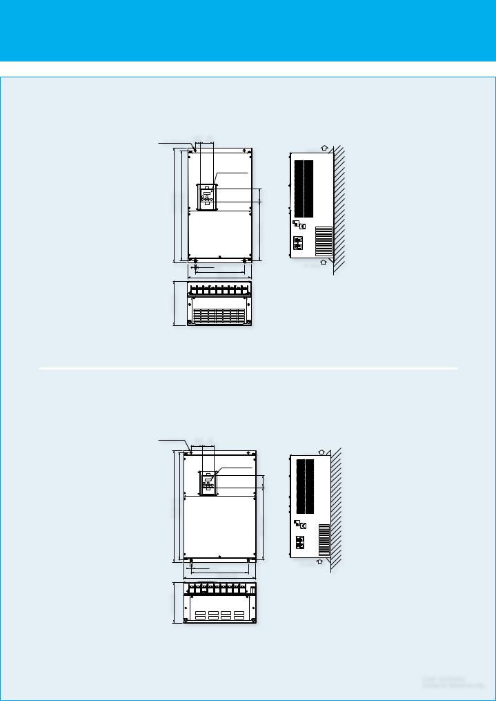
DIMENSIONS |
|
|
|
|
|
|
|
|
|
|
|
|
SJ700-004 037 LFUF2, LFF2 |
|
|
|
SJ700-055 110 LFUF2,LFF2 /HFEF2, HFUF2,HFF2 |
||||||||
SJ700-007 040HFEF2, HFUF2, 007 037HFF2 |
SJ700B-110 150HFF |
|
|
|
||||||||
|
150(5.91) |
|
|
|
|
|
|
210(8.27) |
|
Digital Operator |
|
|
|
|
|
|
|
Exhaust |
|
189(7.44) |
|
|
|||
25(0.98) |
130(5.12) |
|
|
Digital Operator |
|
|
|
|
|
|||
|
|
|
80(3.15) |
|
2-φ7 (φ0.28) |
Exhaust |
||||||
2-φ6(φ0.24) |
80(3.15) |
|
|
|
|
|
24.5(0.97) |
|
||||
164(6.46) 79(3.11) |
|
241(9.49) |
255(10.04) |
|
|
169(6.65) 79(3.11) |
|
246(9.69) |
260(10.274) |
|
Wall |
|
|
|
Wall |
|
|
|
|||||||
|
|
|
|
|
|
|||||||
|
|
|
|
|
|
|
2-7(0.28) |
|
|
|
|
Air intake |
|
|
|
|
|
|
|
|
189(7.44) |
|
|
|
|
|
|
|
|
|
|
|
|
3 -33x28(1.30x1.10) |
|
|||
|
|
|
|
|
|
|
|
|
|
|||
2-6(0.24) |
130(5.12) |
3 -22x25(0.87x0.98) |
|
|
|
Wiring Hole |
|
|||||
|
Air intake |
|
|
|
|
|
|
|||||
|
|
Wiring Hole |
|
|
|
|
|
|
||||
|
|
62(2.44) |
140(5.51) |
|
|
|
203 (7.99) |
13.6(0.25) |
82 (3.23) |
170(6.69) |
|
|
|
143(5.63) |
|
|
|
|
|
||||||
|
|
|
|
|
|
|
||||||
SJ700-150 220 LFUF2,LFF2 /HFEF2, HFUF2,HFF2 |
SJ700-300 LFUF2,LFF2 /HFEF2, HFUF2, HFF2 |
|||||||||||
SJ700B-185 300HFF |
|
|
|
|
|
SJ700B-370HFF |
|
|
|
|
||
2-φ7(φ0.28) |
250(9.84) |
|
|
|
|
Exhaust |
|
Digital Operator |
|
|
||
229(9.02) |
Digital Operator |
45(1.77) |
80(3.15) |
2-φ10 |
|
|
||||||
24.5(0.97) |
80(3.15) |
|
|
Exhaust |
||||||||
|
|
|
|
|
|
|
|
|
|
|||
79(3.11) |
|
|
|
|
|
|
79(3.11) |
|
|
|
|
|
273.4(10.75) |
|
376(14.80) |
390(15.35) |
|
Wall |
368(14.49) |
|
510(20.08) 540(21.26) |
|
|
||
|
|
|
|
|
Wall |
|||||||
|
|
|
|
|
|
|||||||
2-7(0.28) |
229(9.02) |
|
|
|
|
Air intake |
|
|
|
|
|
|
|
3 -42x42.5(1.65x1.67) |
2-10(0.39) |
|
|
|
|
|
|||||
|
|
Wiring Hole |
|
|
|
|
|
Air intake |
||||
|
|
|
|
|
|
|
|
265(10.43) |
|
|
|
|
|
|
|
|
|
|
|
|
|
5-φ25(φ0.98) |
|
||
|
|
|
|
|
190(7.48) |
|
|
310(12.20) |
|
|
||
|
|
|
|
|
|
|
|
Wiring Hole |
|
|||
|
|
|
|
|
|
|
|
|
|
|||
|
244(9.61) |
9.5(0.37) |
83(3.27) |
|
|
|
|
195(7.68) |
|
|
||
|
|
|
|
|
|
|
|
|||||
SJ700-370 450 LFUF2,LFF2 |
|
|
|
SJ700-550 LFUF2,LFF2 |
|
|
||||||
SJ700-370 550 HFEF2, HFUF2,HFF2 |
|
|
|
|||||||||
SJ700B-450 750HFF |
|
|
|
|
|
|
|
Digital Operator |
|
|||
|
Digital Operator |
|
|
125(4.92) 80(3.15) |
|
2-φ12(φ0.47) |
Exhaust |
|||||
32.5(1.28) |
80(3.15) |
2-φ12(φ0.47) |
Exhaust |
|
|
|
|
|
||||
|
|
|
|
|
|
|||||||
277(10.91) 79(3.11) |
|
|
520(20.47) 550(21.65) |
|
Wall |
352(13.87) 79(3.11) |
|
|
670(26.38) |
700(27.56) |
|
|
|
|
|
|
|
|
Wall |
||||||
|
|
|
|
|
|
|
||||||
2-12(0.47) |
300(11.81) |
|
|
|
|
Air intake |
|
|
|
|
|
|
|
|
|
|
|
|
|
|
|
|
|
||
|
|
|
|
|
|
2-12(0.47) |
|
|
|
|
||
|
390(15.35) |
|
|
|
|
|
|
|
|
Air intake |
||
|
|
|
5-41(φ1.61) |
|
|
380(14.96) |
|
|
|
|||
|
|
|
|
|
|
|
6-φ41(φ1.61) |
|
||||
|
|
|
|
Wiring Hole |
|
|
480(18.90) |
|
|
|||
|
|
|
|
|
|
|
Wiring Hole |
|
||||
|
|
|
|
250(9.84) |
|
|
|
|
|
|
||
|
|
|
|
|
|
|
|
|
250(9.84) |
|
[Unit: mm(inch)] |
|
|
|
|
|
|
|
|
|
|
|
|
|
Inches for reference only. |
* Please refer to page 30 for detailed information about compatibility with SJ300.
8
DIMENSIONS |
|
|
|
|
|
SJ700-750, 900HFEF2, HFUF2, HFF2 |
|
|
|
|
|
SJ700B-900, 1100HFF |
|
|
|
|
|
2-φ12(φ0.47) |
32.5 |
80 |
|
|
|
(12.8) (3.15) |
|
|
|||
|
|
|
|
Exhaust |
|
|
|
|
Digital Operator |
|
|
700(27.56) |
670(26.38) |
|
|
79(3.11) |
Wall |
|
|
|
|||
|
|
|
|
357(14.06) |
|
|
|
2-12(0.47) |
Air intake |
|
|
|
|
|
300(11.81) |
|
|
|
|
|
390(15.35) |
|
|
270(10.63) |
|
|
|
|
|
SJ700-1100HFEF2, HFUF2, HFF2 /1320HFEF2, HFF2, 1500HFUF2 |
|
||||
SJ700B-1320, 1600HFF |
|
|
|
|
|
2-φ12(φ0.47) |
62.5 |
80 |
|
|
|
|
|
(2.46) (3.15) |
|
|
|
|
|
|
|
Exhaust |
|
|
|
|
Digital Operator |
|
|
|
|
|
|
79(3.11) |
|
740(29.13) |
710(27.95) |
|
|
|
Wall |
|
|
480(18.90) |
|
||
|
|
2-12(0.47) |
Air intake |
|
|
|
|
|
|
||
|
|
|
380(14.96) |
|
|
|
|
|
480(18.90) |
|
|
270(10.63) |
|
|
|
|
|
|
|
|
|
|
[Unit: mm(inch)] |
|
|
|
|
|
Inches for reference only. |
9 |
|
|
|
|
|
DIMENSIONS
SJ700-1850,2200HFE2 |
Attachment DCreactor(DCL-H-185-H-R),(DCL-H-220-H-R) |
|
|
|
|
15(0.59) |
|
|
|
|
|
305 |
|
W |
|
|
3-φ15(0.59) |
2-M12 Eyebolts |
|
|
|
|
Exhaust |
150 |
|
|
|
||
|
|
|
|
|
|
|
|
|
|||||
|
Digital Operator |
|
|
|
|
|
|
|
|
|
|
X |
|
|
|
|
|
|
|
|
|
|
|
H |
|
|
|
|
|
|
|
965(37.99) |
995(39.17) |
|
|
|
Wall |
230 |
11x18 |
245 |
|
|
|
|
|
|
|
|
|
|
|
|
φ18 |
25 |
|
|
|
|
|
|
|
|
|
|
|
200 |
|
|
|
|
|
|
|
|
|
|
|
|
|
|
|
|
|
|
|
|
|
|
|
|
|
|
|
|
|
50 |
|
57.5 |
15(0.59) |
|
|
(0.59) |
|
|
|
|
370(14.56) |
|
|
Downward details drawing |
|
|
|
15 |
|
|
|
|
Air Intake |
|
|
|
|
||
(22.63) |
290(11.41) |
290(11.41) |
57.5(2.26) |
|
|
|
|
Model |
H |
W |
X |
||
|
695(27.36) |
|
|
|
|
|
4-M12 Screw Holes For Eyebolts |
DCL-H-185-H-R |
350 |
305 |
5 |
||
|
|
|
|
|
|
DCL-H-220-H-R |
395 |
315 |
6 |
||||
|
|
|
|
|
|
|
|
|
|
||||
SJ700-3150HFE2 |
2-M12 Eyebolts |
|
15(0.59) |
|
|
|
|
|
Attachment DCreactor(DCL-H-315-H-R) |
||||
|
φ |
|
|
|
|
|
Exhaust |
|
|
|
|
||
|
|
|
|
2-M12 Screw Holes |
|
|
|
|
|||||
|
3- 15(0.59) |
|
|
|
|
|
|
|
|
|
|||
|
|
|
|
|
|
|
|
|
|
325 |
|
365 |
|
|
|
|
|
|
|
|
|
|
|
150 |
|
|
|
|
|
Digital Operator |
|
|
|
|
|
|
Vent Holes B(*1) |
|
|
|
5 |
|
|
|
|
|
|
|
|
460 |
|
|
|
||
|
|
|
|
|
|
|
|
|
|
|
|
|
|
|
|
|
1270(50.0) |
1300(51.18) |
|
|
|
|
Wall |
|
|
|
|
|
|
|
|
|
|
|
Vent Holes A(*1) |
|
|
|
|
||
|
|
|
|
|
|
|
|
|
|
|
|
|
|
|
|
|
|
|
|
|
|
|
|
285 |
15x25 |
335 |
|
|
|
|
|
|
|
|
|
|
|
|
2-φ14 |
|
25 |
|
|
|
|
|
|
|
|
|
|
285 |
|
|
|
|
|
|
|
|
|
|
|
|
|
|
|
|
|
|
15(0.59) |
|
(0.59) |
|
|
|
|
|
|
|
50 |
|
|
|
|
|
|
|
|
450(17.71) |
|
|
100 |
|
|||
50 |
|
|
15 |
|
|
|
|
|
|
|
|
||
290(11.41) |
290(11.41) |
50(1.96) |
|
|
|
|
Air Intake |
|
|
|
|
||
(1.96) |
|
|
|
|
|
|
Downward details drawing |
||||||
|
680(26.77) |
|
|
|
|
|
4-M12 Screw Holes For Eyebolts |
|
|
||||
|
|
|
|
|
|
|
|
|
|
|
|
||
|
|
|
|
|
|
|
*1 Vent-Holes A are formed on both right and left side portions. Vent-Holes B are just on right side. |
|
|
||||
SJ700-4000HFE2 |
|
|
|
|
|
|
|
|
Attachment DC reactor(DCL-H-400-H-R) |
||||
|
4-φ15(0.59) |
2-M16 Eyebolts |
|
|
2-M16 Screw Holes |
|
|
|
|
|
|||
|
|
|
|
|
|
15(0.59) |
|
|
Exhaust |
|
|
|
|
|
|
|
|
|
|
|
|
|
365 |
|
365 |
|
|
|
|
|
|
|
|
|
|
|
|
|
|
||
|
|
|
|
|
|
|
|
|
|
180 |
|
|
|
|
|
|
|
|
|
|
|
|
|
|
|
|
5 |
|
|
|
|
|
|
|
|
|
|
460 |
|
|
|
Digital Oprator |
|
|
|
|
|
1670(65.74) |
1700(66.92) |
|
|
|
|
|
|
|
|
|
|
|
|
|
Wall |
285 |
15x25 |
335 |
|
||
|
|
|
|
|
|
|
|
|
|
||||
|
|
|
|
|
|
|
|
|
|
|
2-φ14 |
|
25 |
|
|
|
|
|
|
|
|
|
|
285 |
|
|
|
|
|
|
|
|
|
|
|
|
|
|
|
|
|
|
|
|
|
|
|
|
|
|
|
|
|
50 |
|
|
|
|
|
|
|
|
|
|
|
|
|
100 |
|
|
|
|
|
|
|
|
|
|
|
|
|
Downward details drawing |
|
|
15(0.59) |
|
|
|
|
|
15 |
|
450(17.71) |
|
|
|
|
75(2.95) |
|
|
|
|
|
|
|
|
|
|
[Unit: mm(inch)] |
||
300(11.81) |
300(11.81) |
300(11.81) |
|
|
|
Air Intake |
|
|
|
||||
|
|
(0.59) |
|
|
|
|
|||||||
|
|
1050(41.33) |
|
|
|
75(2.95) |
|
4-M16 Screw Holes For Eyebolts |
|
|
|
Inches for reference only. |
|
* 1850H,2200H,3150H and 4000H of US/JP Version:Please contact Hitachi sales office.
10
 Loading...