


SJ200-****EF Type
 Hitachi Industrial Equipment Systems Co.,Ltd.
Compact, high-torque, full-featured drive,
Hitachi's new technology inverter family is suitable for a wide High performance is now within your grasp.
<![endif]>DRIVE FREQUENCY VARIABLE
<![if ! IE]><![endif]>SeriesSJ200
1 |
High starting torque of 200% |
or greater at 1Hz |
|
|
Newly developed technology - Intelligent Sensorless Vector Control - cope |
|
provides optimal high torque without motor tuning. |
2 |
Trip avoidance function |
Advanced over-current trip avoidance function for acceleration, and |
|
|
over-voltage trip avoidance function for deceleration. |
|
Reduced trip likelihood means improved drive system reliability |
|
availability. |
3 |
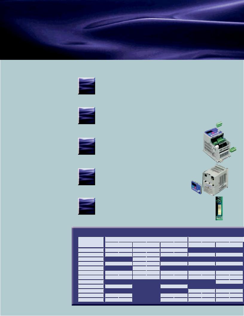
Removable Control Terminal |
Connector type control terminal minimizes control terminal |
|
|
wiring when performing field maintenance. |
|
Input logic is selectable from Sink or Source to match |
|
external device (PLCs, etc.). |
4 |
Removable Keypad |
Keypad (digital operator) can be connected via a cable. |
Remote operation ready. Three LEDs (power, alarm, run)
on the inverter display drive's status.
Operation Source Switch
5 Run command/frequency source are easy to select with a DIP switch.
ApplicablekW(HP)MotorDefaultUSisversionkeypad settingsEuropean1-/3-.phaseversion200V classJP version US version 3-phaseEuropean400Vversionclass
Sliding the switch changes the sources to the control terminals.
Model Configuration
|
|
|
|
|
|
|
|
|
|
|
|
0.2(1/4) |
SJ200-002NFU2 |
SJ200-002NFEF2 |
SJ200-002LFR |
|
|
|
|
||||
0.4(1/2) |
SJ200- |
004NFU2 |
SJ200-004NFEF2 |
SJ200- |
|
004LFR |
SJ200- |
004HFU2 |
SJ200- |
004HFEF2 |
|
0.55(3/4) |
|
|
SJ200-005NFEF2 |
|
|
|
|
|
|
|
|
0.75(1) |
SJ200- |
007NFU2 |
SJ200-007NFEF2 |
SJ200- |
|
007LFR |
SJ200- |
007HFU2 |
SJ200- |
007HFEF2 |
|
1.1(1.5) |
|
|
SJ200-011NFEF2 |
|
|
|
|
|
|
|
|
1.5(2) |
SJ200-015NFU2 |
SJ200-015NFEF2 |
SJ200-015LFR |
SJ200-015HFU2 |
SJ200-015HFEF2 |
||||||
2.2(3) |
SJ200- |
022NFU2 |
SJ200-022NFEF2 |
SJ200- |
|
022LFR |
SJ200- |
022HFU2 |
SJ200-022HFEF2 |
||
3.0(4) |
|
|
|
|
SJ200- |
|
037LFR |
|
|
SJ200- |
030HFEF2 |
3.7(5) |
SJ200- |
037LFU2 |
|
|
|
|
|
|
|
||
4.0(5) |
|
|
|
|
|
|
|
SJ200-040HFU2 |
SJ200-040HFEF2 |
||
5.5(7.5) |
SJ200-055LFU2 |
|
|
SJ200-055LFR |
SJ200-055HFU2 |
SJ200-055HFEF2 |
|||||
7.5(10) |
SJ200-075LFU2 |
|
|
SJ200-075LFR |
SJ200-075HFU2 |
SJ200-075HFEF2 |
|||||
1 1
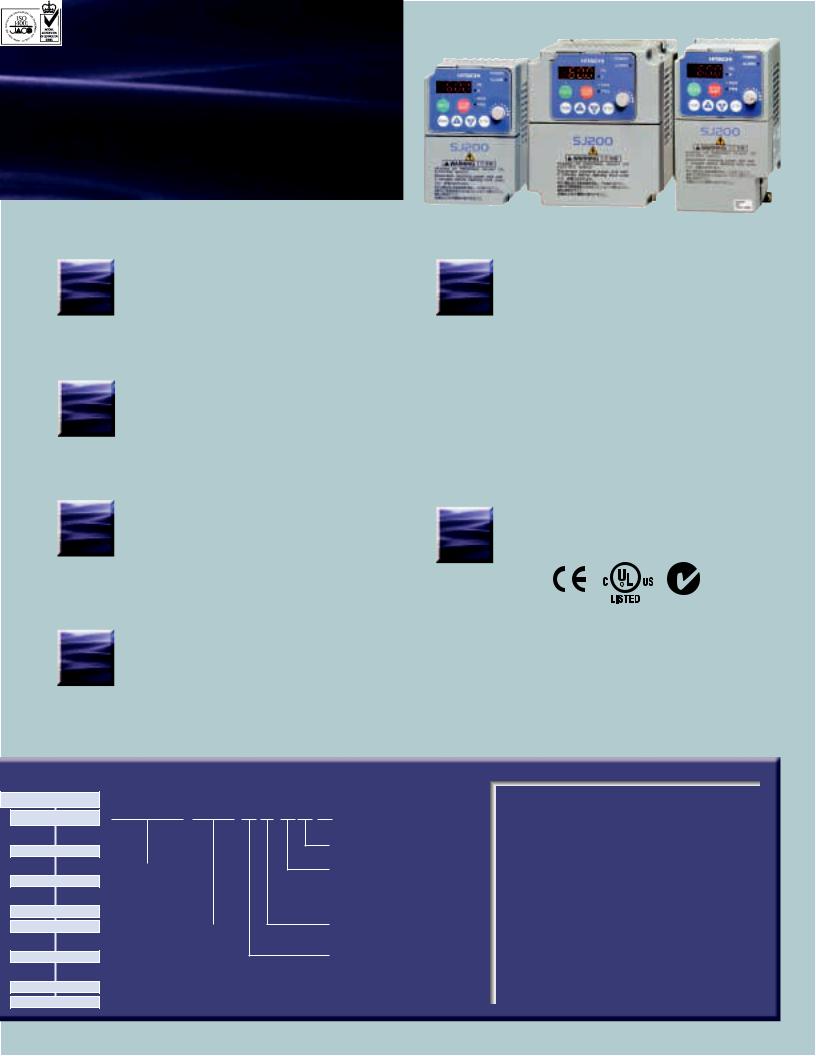
yet easy-to-use.
range of drive applications.
6 |
Improved PID control |
Reverse PID function changes the sign of |
|
|
the deviation value which is the difference |
|
between target and feedback values. |
|
Upper and lower limits from a target value can be |
|
imposed on the inverter output frequency. |
Output Timing
7 and Logic functions
Output terminals can be assigned logical operators AND, OR and XOR with RUN, AL and so on.
ON and OFF delay times are settable for each output terminal. Allows for more flexible system design.
SJ200-****EF2 Type
Versatile Functions
10 |
• Pure analog monitor output (8-bit, 0-10V DC) |
|
• External thermistor terminal (PTC) |
|
• Cooling-fan on/off |
|
• Side-by-side installation |
|
• Regenerative braking circuit |
|
• Instantaneous power failure recovery |
|
• Second motor setting |
|
• Over-voltage suppression at deceleration |
|
• 3-wire control |
|
• RS-485 Serial port with Modbus®-RTU |
|
• Analog input selection |
|
• Second acceleration/deceleration setting |
|
• Jogging |
|
• Auto-carrier frequency reduction |
|
• Unattended start protection (USP) |
|
• Analog input wire-break detection |
8 |
Analog setpoint |
|
calculate functions |
11 |
|
An offset frequency can be added to or subtracted |
from the output frequency when ADD terminal is ON. For example, if output frequency setting is 40Hz and offset frequency is 5Hz, output frequency becomes 45Hz (or 35Hz) when ADD terminal is ON.
Integrated EMC Filter
9 |
Reduces electromagnetic noise. |
|
|
|
(on European-Version units only) |
Model Name Indication
JP version
SJ200-004HFR
SJ200-007HFR
SJ200-015HFR
SJ200-022HFR
SJ200-037HFR
SJ200-055HFR
SJ200-075HFR
SJ200-004 H F E F 2
Series Name
Applicable Motor Capacity
002: 0.2kW(1/4HP)
|
075: 7.5kW(10HP)
 Version Number
F : Integrated EMC filter
U : US version
E : European version R : Japanese version
F : With keypad
Power Source
N : 1 or 3 phase 200V class L : 3-phase 200V class
H : 3-phase 400V class
Global Performance
•Conformity to global standards.
CE, UL, c-UL and c-Tick approvals.
CE UL,c-UL c-Tick
•Network Compatibility.
The SJ200-2 can communicate with PROFIBUS®. CANopen with communication options.
|
|
ISO 14001 |
|
Hitachi variable frequency |
|
|
|
|
|
|
|
|
|||||||||
|
|
EC97J1095 |
|
|
|
|
|
|
|
|
|
||||||||||
|
|
|
drives (inverters) in this |
|
|
|
|
|
|
|
|
||||||||||
|
|
|
|
|
|
|
|
|
|
|
|
|
|
||||||||
|
|
|
|
|
|
brochure are produced at the |
|
|
|
|
|
|
|
|
|||||||
|
|
|
|
|
|
factory registered under the |
|
|
|
|
|
|
|
|
|||||||
|
|
|
|
|
|
ISO 14001 standard for |
|
|
|
|
|
|
|
|
|||||||
|
|
|
|
|
|
environmental management |
|
|
|
|
|
|
|
|
|||||||
|
|
|
|
|
|
system and the ISO 9001 |
|
|
|
|
|
|
|
|
|||||||
|
|
|
|
|
|
standard for inverter quality |
|
|
|
|
|
|
|
|
|||||||
|
|
ISO 9001 |
|
|
|
|
|
|
|
|
|
||||||||||
|
|
|
management system. |
|
|
|
|
|
|
|
|
||||||||||
|
|
JQA-1153 |
|
|
|
|
|
|
|
|
|
|
|
|
|
|
|
|
|
||
|
|
|
|
|
|
|
|
|
|
|
|
|
|
|
|
|
|
|
|
||
CONTENTS |
|
|
|
|
|
|
|
|
|
|
|
|
|
|
|
|
|||||
Features |
|
|
|
|
|
|
|
|
|
|
|
|
|
1-2 |
|||||||
|
|
|
|
|
|
|
|
|
|
|
|
|
|||||||||
Standard Specifications |
|
|
|
|
|
|
|
|
3 |
||||||||||||
|
|
|
|
|
|
|
|
||||||||||||||
Dimensions |
|
|
|
|
|
|
|
|
|
|
|
|
|
|
|
4 |
|||||
|
|
|
|
|
|
|
|
|
|
|
|
|
|
|
|||||||
Operation and Programming |
|
|
|
|
|
|
|
5 |
|||||||||||||
|
|
|
|
|
|
|
|||||||||||||||
Operation / Terminal Functions |
|
|
|
|
|
6 |
|||||||||||||||
|
|
|
|
|
|||||||||||||||||
Function List |
|
|
|
|
|
|
|
|
|
|
7-9 |
||||||||||
|
|
|
|
|
|
|
|
|
|
||||||||||||
Protective Functions |
|
|
|
|
|
10 |
|||||||||||||||
|
|
|
|
|
|||||||||||||||||
Connecting Diagram |
|
|
|
|
|
|
|
|
|
11 |
|||||||||||
|
|
|
|
|
|
|
|
|
|||||||||||||
Wiring and Accessories |
|
|
12 |
||||||||||||||||||
|
|
||||||||||||||||||||
For Correct Operation |
|
13-14 |
|||||||||||||||||||
|
|||||||||||||||||||||
|
|
|
|
|
|
|
|
|
|
|
|
|
|
|
|
|
|
|
|
|
|
2 2

Standard Specifications
1-/3-phase 200V class
Model SJ200- |
|
European Version |
002NFEF2 |
004NFEF2 |
005NFEF2 |
007NFEF2 |
011NFEF2 |
015NFEF2 |
022NFEF2 |
|
- |
|
- |
- |
|
US Version |
002NFU2 |
004NFU2 |
- |
007NFU2 |
- |
015NFU2 |
022NFU2 |
|
037LFU2 |
|
055LFU2 |
075LFU2 |
|
|
|
|
|
|||||||||||
|
Applicable motor size, 4-pole kW(HP) *1 |
0.2(1/4) |
0.4(1/2) |
0.55(3/4) |
0.75(1) |
1.1(1.5) |
1.5 (2) |
2.2(3) |
|
3.7(5) |
|
5.5(7.5) |
7.5(10) |
|
|
Rated capacity |
200V |
0.5 |
0.9 |
1.0 |
1.4 |
1.7 |
2.8 |
3.8 |
|
6.0 |
|
7.5 |
11 |
Output Ratings |
240V |
0.6 |
1.2 |
1.3 |
2.0 |
2.1 |
3.3 |
4.5 |
|
7.2 |
|
9.9 |
13.3 |
|
|
|
|
||||||||||||
Rated output current (A) *2 |
1.6 |
2.6 |
3.0 |
4.0 |
5.0 |
8.0 |
11.0 |
|
17.5 |
|
24 |
32 |
||
|
|
|
||||||||||||
|
Overload capacity(output current) |
|
|
|
|
150% for 60 sec. |
|
|
|
|
|
|
||
|
Rated output voltage (V) |
|
|
3-phase (3-wire) 200 to 240V (corresponding to input voltage) |
|
|
||||||||
Input Rating |
Rated input voltage (V) |
|
|
|
1-/3-phase 200 to 240V±10%, 50/60Hz±5% |
|
|
|
|
|
||||
Enclosure *4 |
|
|
|
|
|
|
IP20 |
|
|
|
|
|
|
|
Cooling method |
|
|
|
|
Self-cooling |
|
|
|
|
Force ventilation |
|
|
||
Weight (kg) |
|
-NFEF |
0.8 |
0.95 |
0.95 |
1.4 |
1.4 |
1.9 |
1.9 |
|
- |
|
- |
- |
|
-NFU/LFU |
0.7 |
0.85 |
- |
1.3 |
- |
1.8 |
1.8 |
|
1.9 |
|
3.5 |
3.5 |
|
|
|
|
|
|||||||||||
3-phase 400V class
Model SJ200- |
|
European Version |
004HFEF2 |
007HFEF2 |
015HFEF2 |
|
022HFEF2 |
|
030HFEF2 |
|
040HFEF2 |
055HFEF2 |
075HFEF2 |
|
US Version |
004HFU2 |
007HFU2 |
015HFU2 |
|
022HFU2 |
|
- |
|
040HFU2 |
055HFU2 |
075HFU2 |
|
|
|
|
|
|
|||||||||
|
Applicable motor size, 4-pole kW(HP) *1 |
0.4(1/2) |
0.75(1) |
1.5 (2) |
|
2.2(3) |
|
3(4) |
|
3.7(5) |
5.5(7.5) |
7.5(10) |
|
|
Rated capacity |
400V |
1.0 |
1.7 |
2.6 |
|
3.8 |
|
5.4 |
|
5.9 |
7.5 |
11 |
Output Ratings |
480V |
1.2 |
2.0 |
3.1 |
|
4.5 |
|
6.5 |
|
7.1 |
10.8 |
13.3 |
|
|
|
|
|
||||||||||
Rated output current (A) *2 |
1.5 |
2.5 |
3.8 |
|
5.5 |
|
7.8 |
|
8.6 |
13 |
16 |
||
|
|
|
|
||||||||||
|
Overload capacity(output current) |
|
|
|
|
150% for 60 sec. |
|
|
|
||||
|
Rated output voltage (V) |
|
|
3-phase (3-wire) 380 to 480V (corresponding to input voltage) |
|
|
|||||||
Input Rating |
Rated input voltage (V) |
|
|
|
3-phase 380 to 480V±10%, 50/60Hz±5% |
|
|
|
|||||
Enclosure *4 |
|
|
|
|
|
|
|
IP20 |
|
|
|
||
Cooling method |
|
|
Self-cooling |
|
|
|
|
Force ventilation |
|
|
|||
Weight (kg) |
|
-HFEF |
1.4 |
1.8 |
1.9 |
|
1.9 |
|
1.9 |
|
1.9 |
3.8 |
3.8 |
|
-HFU |
1.3 |
1.7 |
1.8 |
|
1.8 |
|
- |
|
1.8 |
3.5 |
3.5 |
|
|
|
|
|
|
|||||||||
General Specifications
|
Item |
|
General Specifications |
||
|
Control method |
|
Line-to-line sine wave pulse-width modulation (PWM) control |
||
|
Output frequency range *5 |
|
0.5 to 400Hz |
||
|
Frequency accuracy *6 |
|
Digital command :±0.01%, Analog command±0.2% (25 ±10˚C) |
||
|
Frequency setting resolution |
Digital: 0.1Hz, Analog: (max frequency)/1000 |
|||
Control |
Voltage/Frequency Characteristic |
V/f control,V/f variable (constant torque, reduced torque) |
|||
Acceleration/deceleration time |
0.01 to 3000 sec. (linear, sigmoid), two-stage accel./decel. |
||||
|
|||||
|
Starting torque *7 |
|
200%/1Hz |
||
|
Carrier frequency range |
|
2.0 to 14.0kHz |
||
|
Protective functions |
|
Over-current, over-voltage, under-voltage, overload, overheat, ground fault at power-on, overload limit, input over-voltage, external trip, |
||
|
|
EEPROM error, CPU error, USP error, braking resistor overload, LAD stop at over-voltage, over-current suppression, Termister error |
|||
|
|
|
|
||
|
Specification |
|
10kohm input impedance, sink/source logic selectable |
||
|
|
|
|
FW(Forward), RV(Reverse), CF1-CF4(Multispeed command), JG(Jogging), DB(External DC braking), SET(Second motor constants |
|
Input terminal |
|
|
|
setting), 2CH(Second accel./decel.), FRS(Free-run stop), EXT(External trip), USP(Unattended start protection), SFT(Software lock), |
|
Functions |
|
AT(Analog input selection), RS(Reset), PTC(Thermistor input) *8, STA(3-wire start), STP(3-wire stop), F/R(3-wire fwd./rev.), PID(PID |
|||
|
|
|
|
On/Off), PIDC(PID reset), UP/DWN(Remote-controlled accel./decel.) , UDC(Remote-controlled data clearing), OPE(Operator control), |
|
|
|
|
|
ADD(ADD frequency enable), F-TM(force terminal mode), RDY(quick start enable),S-ST(Special-Set 2nd Motor Data), NO(Not selected) |
|
|
|
|
Specification |
27V DC 50mA max open collector output, 2 terminals |
|
|
|
|
1c output 250V AC/30V DC 2.5A relay (AL0, AL1, AL2 terminals) |
||
|
Intelligent output |
|
|
||
|
|
|
RUN(run signal), FA1(Frequency arrival type 1 - constant speed), FA2(Frequency arrival type 2 - over-frequency), OL(overload |
||
|
terminal |
|
|
||
Output signal |
|
Function |
advance notice signal), OD(Output deviation for PID control), AL(alarm signal), DC(Wire brake detect on analog input), FBV(PID |
||
|
|
||||
|
|
|
|
Second Stage Output), NDC(ModBus Network Detection Signal), LOG(Logic Output Function), ODC(Option Card Detection Signal) |
|
|
Analog output terminal |
|
Specification |
0 to 10V DC (8-bit resolution) |
|
|
|
Function |
Analog Frequency monitor, analog current monitor |
||
|
|
|
|||
|
|
|
Specification |
4-digits 7 segment LEDs |
|
|
Display |
|
Function |
Parameter setting, output frequency, output current, motor torque, scaled value of output frequency, trip history, I/O terminal condition, |
|
Operator |
|
|
input power, output voltage. Rotation direction, PID Feedback, RON time, Power-on time. |
||
|
|
|
|||
|
Status LED |
|
Power, Alarm, Run, Prg, Hz and A |
||
|
Interface |
|
Potentiometer, RUN, STOP/RESET, UP, DOWN, FUN and STR keys |
||
|
|
|
Operator keypad |
Up and Down keys / Value settings or analog setting via potentiometer on operator keypad |
|
|
Frequency setting |
|
External signal |
0 to 10 V DC, 4 to 20 mA |
|
Operation |
|
|
Serial port |
RS485 interface (Modbus RTU) |
|
|
|
Operator Keypad |
Run key / Stop key (change FW/RV by function command) |
||
|
|
|
|||
|
FW/RV Run |
|
External signal |
FW Run/Stop (NO contact), RV set by terminal assignment (NC/NO), 3-wire input available |
|
|
|
|
Serial port |
RS485 interface (Modbus RTU) |
|
|
Operating temperature |
|
-10 to 40˚C(carrier frequency ≤5kHz) |
||
|
|
-10 to 50˚C(derating for carrier frequency and output current required) |
|||
|
|
|
|
||
Environment |
Storage temperature |
|
-20 to 65˚C |
||
Humidity |
|
20 to 90% RH |
|||
|
|
||||
|
Vibration |
|
5.9mm/s2 (0.6G) 10 to 55Hz |
||
|
Location |
|
Altitude 1,000 m or less, indoors (no corrosive gasses or dust) |
||
|
|
|
|
AVR (Automatic Voltage Regulation), V/f characteristic selection, accel./ |
|
|
Other functions |
|
decel. curve selection, frequency upper/lower limit, 16 stage multispeed, PID control, frequency jump, external frequency input bias |
||
|
|
|
|
start/end, jogging, automatic torque boost, cooling fan On/Off, trip history etc. |
|
|
Coating color |
|
Gray (Munsell 8.5YR6.2/0.2) |
||
|
Options |
|
Remote operator with copy function (SRW-0EX), EMI filters, input/output reactors, DC reactors, radio noise filters, braking resistors, |
||
|
|
braking units, LCR filter, communication cables (ICS-1, 3), programming software (being planned) |
|||
|
|
|
|
||
Note 1: The applicable motor refers to Hitachi standard 3-phase motor (4-pole). When using other motors, care must be taken to prevent the rated motor current (50/60 Hz) from exceeding the rated output current of the inverter.
Note 2: The output voltage decreases as the main supply voltage decreases (except when using the AVR function). In any case, the output voltage cannot exceed the input power supply voltage.
Note 3: The braking torque via capacitive feedback is the average deceleration torque at the shortest deceleration (stopping from 50/60 Hz as indicated). It is not continuous regenerative braking torque. The average decel torque varies with motor loss. This value decreases when operating beyond 50 Hz. If a large regenerative torque is required, the optional regenerative braking resistor should be used.
Note 4: The protection method conforms to JEM 1030. NEMA1 with optional NEMA1 kit.
Note 5: To operate the motor beyond 50/60 Hz, consult the motor manufacturer for the maximum allowable rotation speed. Note 6: The output frequency may exceed the maximum frequency setting (A004 or A204) for automatic stabilization control. Note 7: Automatic torque boost adjustment shall be required.
Note 8: Only terminal 5 is assignable the PTC (thermistor) function.
3

Dimensions
•SJ200-002 - 004NFU2
•SJ200-007 - 022NFU2 •SJ200-030 - 037LFU2 •SJ200-004 - 040HFU2
| <![if ! IE]> <![endif]>(0.24)6 |
5 (0.20) |
|
|
|
|
|
|
|
|
|
|
<![if ! IE]> <![endif]>110 (4.48) |
<![if ! IE]> <![endif]>120 (4.90) |
|
|
67 (2.64) |
5 (0.20) |
||
|
|
|
|
|
|
80 (3.15) |
<![if ! IE]> <![endif]>7(0.16) |
|
|
|
|
|
||
|
|
<![if ! IE]> <![endif]>(0.102) |
<![if ! IE]> <![endif]>D |
|
|
|
<![if ! IE]> <![endif]>2.6 |
|
|
|
|
|
2- Ø5 |
|
|
|
|
<![if ! IE]> <![endif]>118 (4.64) |
<![if ! IE]> <![endif]>130 (5.12) |
|
|
|
<![if ! IE]> <![endif]>4 |
|
|
98 (3.86) |
5 (0.20) |
||
|
|
|
|
|
|
110 (4.33) |
<![if ! IE]> <![endif]>7(0.16) |
|
|
|
|
|
||
|
|
|
<![if ! IE]> <![endif]>D |
|
|
|
<![if ! IE]> <![endif]>6(0.24) |
|
|
•SJ200-055,075LFU2 2-ø6
•SJ200-055,075HFU2
6 (0.24)
164 (6.46)
180 (7.09)
|
•SJ200-002 - 005NFEF2 |
<![if ! IE]> <![endif]>(0.24) |
5 (0.20) |
|
|
|
|
|
<![if ! IE]> <![endif]>6 |
|
|
|
|
|
|
|
<![if ! IE]> <![endif]>110 (4.48) |
<![if ! IE]> <![endif]>120 (4.90) |
<![if ! IE]> <![endif]>140 (5.51) |
|
model |
D |
|
5 (0.20) |
|
||
002NFU2 |
103(4.06) |
|
67 (2.64) |
<![if ! IE]> <![endif]>7(0.16) |
model |
D |
|
80 (3.15) |
|||||
004NFU2 |
117(4.61) |
|
||||
|
|
|
|
|
002NFEF2 |
103(4.06) |
|
|
|
|
|
004NFEF2 |
117(4.61) |
|
|
|
|
|
005NFEF2 |
|
|
|
|
<![if ! IE]> <![endif]>(0.102) |
|
|
|
|
|
|
<![if ! IE]> <![endif]>D |
|
||
|
|
|
<![if ! IE]> <![endif]>2.6 |
|
|
|
•SJ200-007 - 022NFEF2 |
2- Ø5 |
||
•SJ200-004 - 040HFEF2 |
|
|
|
|
<![if ! IE]> <![endif]>118 (4.64) |
<![if ! IE]> <![endif]>130 (5.12) |
<![if ! IE]> <![endif]>155 (6.10) |
|
<![if ! IE]> <![endif]>4 |
|
|
model D
007NFU2 139(5.47) 004HFU2
015,022NFU2
037LFU2 166(6.54)
007-040HFU2
007NFU2, 004HFU2, 007HFU2, : without FAN
98 (3.86)
110 (4.33)
5 (0.20)
<![if ! IE]><![endif]>D 7(0.16)
<![if ! IE]><![endif]>6 (0.24)
•SJ200-055,075HFEF2 2-ø6
model D
007,011NFEF2
004HFEF2
139(5.47)
015,022NFEF2
007-040HFEF2
166(6.54)
007NFEF2, 004HFEF2 and 007HFEF2
:without FAN
* Potentiometer knob can be removed.
| <![if ! IE]> <![endif]>205 (8.07) |
<![if ! IE]> <![endif]>220 (8.66) |
|
<![if ! IE]> <![endif]>205 (8.07) |
<![if ! IE]> <![endif]>220 (8.66) |
<![if ! IE]> <![endif]>250 (9.84) |
| <![if ! IE]> <![endif]>6.5(0.25) |
|
6 (0.24) |
<![if ! IE]> <![endif]>(0.25) |
|
|
|
|
164 (6.46) |
|
|
|
|
|
180 (7.09) |
<![if ! IE]> <![endif]>6.5 |
|
|
|
|
|
|
|
|
| <![if ! IE]> <![endif]>(0.22) |
<![if ! IE]> <![endif]>155 (6.10) |
|
|
<![if ! IE]> <![endif]>(0.22) |
<![if ! IE]> <![endif]>155 (6.10) |
| <![if ! IE]> <![endif]>5.5 |
|
|
|
<![if ! IE]> <![endif]>5.5 |
[Unit : mm(inch)] |
|
|
|
Inches for reference only. |
||
|
|
|
|
|
Keypad (digital operator), provided as standard
•OPE - SRmini |
70 (2.76) |
7 |
10 |
2.7 |
2-Ø4 |
20.5 (0.83) |
18 (0.73) |
|
|
|
|
|
|
|
|
|
<![if ! IE]> <![endif]>(2.24) |
|
|
|
<![if ! IE]> <![endif]>15.3 |
<![if ! IE]> <![endif]>(0.62) |
<![if ! IE]> <![endif]>18 (0.73) |
|
<![if ! IE]> <![endif]>55 |
|
|
|
<![if ! IE]> <![endif]>16.5 |
<![if ! IE]> <![endif]>(0.67) |
<![if ! IE]> <![endif]>8.8 (0.36) |
|
|
|
|
|
|
|
[Unit : mm(inch)] |
|
2-M3 depth 5 (Reverse side) |
|
|
|
Mounting holes |
Inches for reference only. |
|
4
 Loading...