


vk-s454r
Table of contents
 Loading...
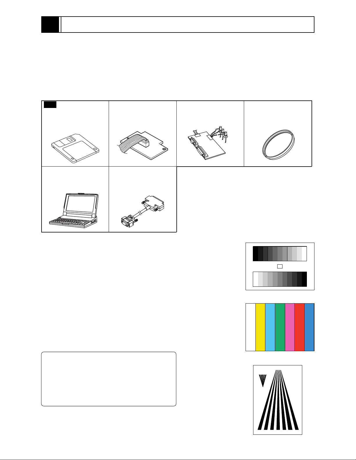
6
Adjustment
6-1 Preparations for Adjustment
All adjustments are performed using the adjustment program (ZMAP: Zoom camera Manual
Adjustment Program) and personal computer (PC). If error message appears during adjustment,
refer to "6-9 Error Messages and Countermeasure".
6-1-1 List of equipment and jigs
New
Adjustment Floppy
Disk (Adjustment
Program)
Personal Computer (PC)
[Goods on the Market]
*1
DSP Interface Connect
Jig No. 7069179
RS-232C Cable (9 or 25
pins) Straight Type
[Goods on the Market]
DSP-R Jig
No.7099448
*1: The adjustment floppy disk is not for sale: It will
6-1-2 List of test equipment and charts
1) Gray scale chart
2) Color bar chart
3) Backfocus chart
4) Oscilloscope
5) Vectorscope
6) Digital voltmeter (DVM)
7) 3100K light box
8) Color Monitor
9) DC power supply for the video camera
10) DC power supply for the DSP-R jig
C12 Light Balancing
Filter No.7099369
be supplied only when service maintenance
contract is concluded.
Gray Scale Chart
Color Bar Chart
Information:
It is recommended that you use a vectorscope
when performing the chroma gain adjustment.
You can use an oscilloscope instead:
Note, however, that the adjustment accuracy
will be lower.
Backfocus Chart
6 - 1

Adjustment > Preparations for Adjustment
6-1-3 Connections for adjustment
Connect the video camera to the test equipment and jigs as shown in Fig. 6-1-1
LIGHT
BOX
DC POWER
SUPPLY
(9V/3A)
+
GND
DC POWER
SUPPLY
(5V/1A)
+
GND
VIDEO CAMERA
PG1601
DSP INTERFACE CONNECT JIG
1
RD WHT
2
SD BRW
3
GND BRW
4
+B BRW
5
GND BRW
6
VIDEO BRW
7
GND(VIDEO) BRW
8
EX. FV BRW
9
GND BRW
YEL
RED
9PIN FLAT CABLE
(ACCESSORY)
9
1
2345
1
6
78
WHT
BLK
VECTORSCOPE
To
INPUT
To
OUTPUT
OSCILLOSCOPE
CH1
CH2
9
When using an
osilloscope only
PERSONAL
COMPUTER
To VIDEO IN
TERMINAL
COLOR
MONITOR
BLK
DSP-R JIG
RS-232C
CABLE
Fig. 6-1-1 Connections for Adjustment
Note:
1) The adjustment program will not operate normally unless the video camera, PC and DSP-R jigs
are all turned on.
2) Take care with the following when pointing the video camera at a chart (light box):
a) Focus the chart correctly.
b) Set the chart (light box) 30-50 cm away from the lens surface, and avoid any effects from
surrounding light (except for a case where some designation is given).
3) Be sure to connect the video output of video camera to a color video monitor (terminate the video
output with 75 ohm):
If the video output is not connected to the monitor (and if it is not terminated with 75 ohm), the
output video signal level cannot be measured correctly.
4) Use light box that does not flicker and whose color temperature is controlled, for adjustment. If
an inappropriate light box is used, precise adjustment will not be possible, and the adjustment
program will not operate normally.
6 - 2

Adjustment > Preparations for Adjustment
6-1-4 Setting test equipment
(1) Oscilloscope
The names of switches, knobs, modes, etc. of oscilloscope may vary slightly depending on the
manufacturer or model. Since some oscilloscopes may have switches, etc. other than the above that
must be set, see the instruction manual of the particular oscilloscope for details.
1) Probe: 10:1
2) TIME/DIV: 10 or 20 µs (except for a case where some designation is given)
3) VOLTS/DIV: Will vary depending on the measurement object (except for a case where
some designation is given)
4) Synchronization: Internal sync (except for a case where some designation is given)
5) AC/DC/GND: AC (except for a case where some designation is given)
(2) Vectorscope
1) SATURATION: 75%
6-1-5 Starting adjustment program (ZMAP)
1) Connect the video camera, DSP-R jig and PC as shown in
Fig. 2-1, and supply power to them. If the connection of
jig, etc. is inappropriate or power is not supplied, the
adjustment program will not start normally.
2) Operate the PC to start MS-DOS. For details on how to
start MS-DOS, refer to the instruction manual of PC,
since this varies for each PC.
3) Make sure that the adjustment floppy disk is writeprotected.
4) Insert the adjustment floppy disk into the floppy disk
drive of PC.
5) Use the PC keyboard to type A: and press Enter
key.
(See the MS-DOS screen-1 and 2)
The letter to be input is to designate the drive into which
the adjustment floppy disk has been inserted. If using a
drive other than A, designate the drive.
6) Input ZMAP_2002
(space)
1
and press Enter
key. (See the
ZMAP input screen)
The number to be input after a space is to designate the
serial port no. of PC. If the PC has two or more serial
ports, and the DSP-R jig is connected to a port other
than serial port 1, input the serial port number.
MS-DOS screen-1
C>
Input A and press Enter key.
MS-DOS screen-2
C>A:
A>
Input ZMAP_2002 (space) 1.
ZMAP input screen
C>A:
A>ZMAP_2002 1
Press Enter key.
(Continued on next page)
6 - 3

Adjustment > Preparations for Adjustment
7) The ZMAP will start: Make sure that the model select
screen appears on the PC display. (See the model select
screen)
If the model select screen does not appear, make sure of
the following:
a) Power is supplied to the video camera and DSP-R jig.
b) The designation of drive (in step 5) is correct.
c) The designation of serial port is correct.
d) The correct adjustment floppy disk has been correctly
inserted.
8) If the appropriate model is displayed on the model select
screen, input the number to PC. If the appropriate model
name is not shown on the model select screen, input P to
PC until the model name appears. If an erroneous model
name or number is selected, misoperation message will
appear on PC display: Press any key to restore the model
select screen.
9) The screen for verifying the model name will appear on
PC display: If it is correct, input Y to PC. If it is incorrect,
input N and start over (from step 8).
10) Make sure that the main menu appears on PC display: If
it does not appear, check whether model selection (in step
8) is correct.
(Continued from preceding page)
Model select screen
***********************************************************
***********************************************************
MODEL SELECT
[1] ЧЧЧЧЧЧЧЧ
[2] ЧЧЧЧЧЧЧЧ
[3] ЧЧЧЧЧЧЧЧ
[4] ЧЧЧЧЧЧЧЧ
[5] ЧЧЧЧЧЧЧЧ
[P] NEXT SELECTION
[ESC] END
Please select the type of the set
Press [1] - [5] or [P] or [ESC]
Model select (Input the
number).
Screen for verifying model name
Selected model is ЧЧЧЧЧЧЧЧ
Are you sure ? (Y/N)
Input Y.
Main menu
***********************************************************
MANUAL ADJUSTMENT PROGRAM
***********************************************************
[A] DATA INITIALIZE
[B] ELECTRIC VOLUME
[C] ADJUSTMENT
[D] AUTO FOCUS
[E] SPOT NOISE
[F] IR CONTROL
[ESC] END
Please select [A] - [F] or [ESC]
To terminate the adjustment program (ZMAP):
Press the Esc key once to three times until the PC display
returns from each menu screen to the MS-DOS screen. When
the MS-DOS screen appears on PC display, turn off the video
camera and jig.
Information
Misoperation message
CAN NOT FIND THE DATA FILE
**** PRESS ANY KEY ****
6 - 4
Adjustment > List of Adjustment Items
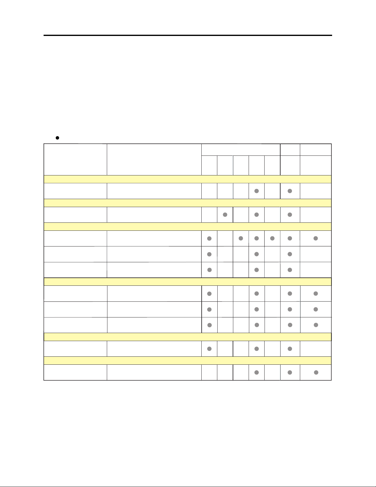
6-2 List of Adjustment Items
6-2-1 List of adjustments needed after replacing major
The following table shows the adjustment items, their purposes, and whether or not check is
required after replacing major components.
The components shown in the table below are the minimum to be checked after replacing major
components: If several components have been replaced - or depending on the cause of a defect more
components may need to be checked.
Table 6-2-1 List of adjustments needed after replacing major
: :
: CHECK
: :
Items Purpose Adjustment
Data Initialize
Electrical Parts
IC1001 IC1101 IC1201
IC1202
IC1250
(*1)
IC1351
Circuit
Board
PC
(*1)
Other
Lens Block
Data Initilize (*2)
Electric Volume
CDS Sampling Pulse
Camera Adjustment (Adjustment)
Auto Iris
White Balance
Chroma Gain
Auto Focus
Zoom/Focus Tracking
AF Noise Level
Check of Zoom/Focus
Tr ac e
Spot Noise
Spot Noise
IR Control
Initilizing EEPROM.
To suppress noise in the CCD sensor
output signal and maximize the signal
level.
To set the iris control data.
To input the automatic white balance
control data.
To set the color satuation under the
reference color temperrature.
To set the out-of -focus correction level
during zooming.
To set the noise level in the autofocus
circuit.
To check the autofocus adjustment.
To correct spot noise.
IR Control To set the IR filter control data.
*1: When replacing the PC circuit board or EEPROM, be sure to perform all adjustments only after "Data
Initialize".
*2: Since all adjustments must be performed any time "Data Initialize" is done, do not perform it
indiscriminately.
6 - 5
Adjustment > List of Adjustment Items
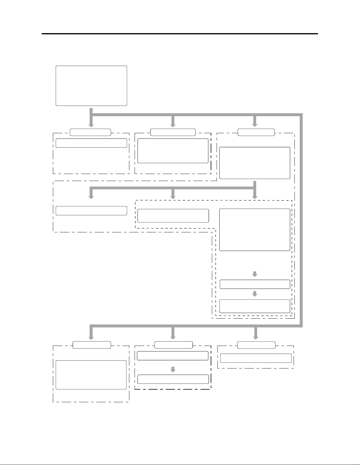
6-2-2 Adjustment flowchart
Main menu
***********************************************************
MANUAL ADJUSTMENT PROGRAM
***********************************************************
[A] DATA INITIALIZE
[B] ELECTRIC VOLUME
[C] ADJUSTMENT
[D] AUTO FOCUS
[E] SPOT NOISE
[F] IR CONTROL
[ESC] END
Please select [A] - [F] or [ESC]
Input: A Input: B Input: C
Data initialize
<< DATA WRITING >>
START TO SEND DATA. (Y/N)
Note:
Refer to "6-3 Data Initialize".
Input: 1
Auto Iris Control
ADJUSTMENT FINISHED
PRESS ANY KEY
Electrical volume Adjustment
***********************************************************
***********************************************************
Input: 1
ELECTRIC VOLUME
[1] CDS SAMPLING PULSE
[ESC] RETURN TO MAIN MENU
Please select [1] or [ESC]
Input: 2
[For VK-S274R/S274ER]
Adjustment menu
***********************************************************
***********************************************************
[1] AUTO IRIS CONTROL
[2] WHITE BALANCE
[3] CHROMA GAIN
[ESC] RETURN TO MAIN MENU
Please select [1] - [3] or [ESC]
Input: 3
White Balance Chroma Gain
<< ADJUSTMENT OF WHITE BALANCE >>
ADJUSTMENT FINISHED
PRESS ANY KEY
<< ADJUSTMENT OF CHROMA GAIN >>
ROUGH ADJUSTMENT
[U] CHROMA GAIN UP
[D] CHROMA GAIN DOWN
FINE ADJUSTMENT
[Crt] + [U] CHROMA GAIN UP
[Crt] + [D] CHROMA GAIN DOWN
[ENTER] SAVE & RETURN TO MENU
[ESC] QUIT
Adjust: Set the red vector to
240% ± 5% of burst
vector.
<< ADJUSTMENT OF CHROMA GAIN >>
DATA WRITING INTO EEPROM
<< ADJUSTMENT OF CHROMA GAIN >>
ADJUSTMENT FINISHED
ADJUSTMENT
PRESS ANY KEY
Input: D Input: E
Auto Focus
AF menu
***********************************************************
AUTO FOCUS ADJUSTMENT
***********************************************************
[1] ADJUSTMENT OF ZOOM/FOCUS TRACKING
[2] ADJUSTMENT OF AF NOISE LEVEL
[3] CHECK OF ZOOM/FOCUS TRACE
[ESC] RETURN TO MENU
Please select [1] - [3] or [ESC]
Input: 1, 2 or 3
Input: Y
Fig. 6-2-1 Adjustment Flowchart
Spot Noise
<< DATA WRITING >>
START TO SEND DATA. (Y/N)
FINISHED WRITING DATA
PRESS ANY KEY
6 - 6
Input: F
IR Control
FINISHED WRITING DATA
PRESS ANY KEY
Loading...