


Video Corner
Servicing the Hitachi VM Series
camcorder
By Timothy W. Durhan
VHS camcorders from all manufacturers have a lot in common. They have to
have a lot of similarities in order to record
and play back on the same VHS tape cassette. On the other hand, manufacturers
also have a great deal of freedom in the
details of how they design and construct
their camcorders.
This article will describe procedures
for servicing Hitachi models VM 3000
through VM 5000 camcorders. Many of
the problem symptoms and actions to correct the problems will also apply to other
brands and models of camcorder.
Hitachi manufactured thousands of
camcorders in the late 80’s as models VM
3000 to VM 5000. Radio Shack, RCA and
Sears sold these units too, using their own
names and model numbers. All feature
the same tape mechanism. The capstan,
Durhan is an independent consumer electronics
ing
technician
and a freelance
technical writer.
service
mode cam and tape wind functions are
actuated by belts.
Symptoms of worn rubber parts
You probably know rubber parts dete-
riorate in time, even if they’re not used
often. Chances are, a five or six year old
camcorder will need new rubber. Some
common symptoms of worn belt problems include:
l Tape starts to load, then camcorder
shuts off.
*Tape runs, then after a while, shuts off.
l Camcorder eats tapes.
l Tapes won’t play or record.
If you have serviced VCRs with similar problems, you know it’s not too difficult to replace worn rubber parts.
Many VCR technicians are reluctant to
service camcorders, even though they
wouldn’t think twice about opening up
and repairing a hand held remote control.
If you can repair a remote control unit
without destroying the case or losing any
of the buttons, performing a mechanical
repair on a camcorder shouldn’t be too
difficult. Lost screws, pinched wires and
broken pc boards can be avoided by using
a systematic disassembly and reassembly
procedure.
Getting started
Start by powering up the camcorder
using the customer’s ac adapter, since a
defective battery may also be the cause of
any of the symptoms mentioned earlier.
Moreover, there is nothing more frustrating than running out of power in the middle of a repair. If your customer didn’t include the adapter along with their camcorder, put this repair on hold until they do.
Slide the power switch to on, and press
eject. If the mode belt is in good shape,
the cassette lid should pop up. If it doesn’t
1. Upper Cylinder (Video Head)
2. Audio/Control (A/C Head)
3.
Dew Sensor
4.
Pressure Roller
5.
Capstan Motor
6.
Capstan Flywheel
7. Take-up End Sensor
8. Take-up Reel Disk
9.
End Lump
10. Take-up Guide Roller
11.
Supply Reed Disk
12.
Tension Band
13.
Tension Arm
14. Supply Guide Roller
15. Supply End Sensor
16.
Impedance Roller
17. Full Erase Head
18.
Cylinder Brush
Figure 1. Tape transport mechanism-Top View.
60 Electronic Servicing
&
Technology November 1993
open, you’ll have to trigger the carriage
latch manually.
To open this latch manually, unplug the
ac adapter and remove the two screws that
hold the cassette lid on. Carefully slide
off the lid, and set it out of your way. On
the right side at the top edge of the chassis is a tiny latch (Figure 1). Gently move
the latch to one side with a small screwdriver or pick. The housing should pop
up, and you can remove the video tape, if
one is stuck inside.
Performing the diagnosis
Once the cassette lid is off, power-up
the camcorder again. Cover up the sense
LED in the center of the transport with
black tape or other suitable light shield,
and press play. Again, if the mode belt is
in good shape, the guide posts should
move to their stoppers, and the drum will
start to spin.
To determine whether the tape-wind
belt is doing its job, use a torque gauge
on the take-up spindle. Hitachi recommends
80gm-cm
to 1 lOgm-cm. If you
lack such a handy tool, you can try to stop
the spindle with your fingers. Obviously,
if the spindle doesn’t turn, or stops very
easily, the tape-wind belt is defective. Is
the pinchroller turning?
If the take-up spindle and pinchroller
aren’t moving, the capstan belt is defective, or there may be an electronic fault.
Listen closely for the sound of the capstan motor spinning. You will have to
press the play button continually in this
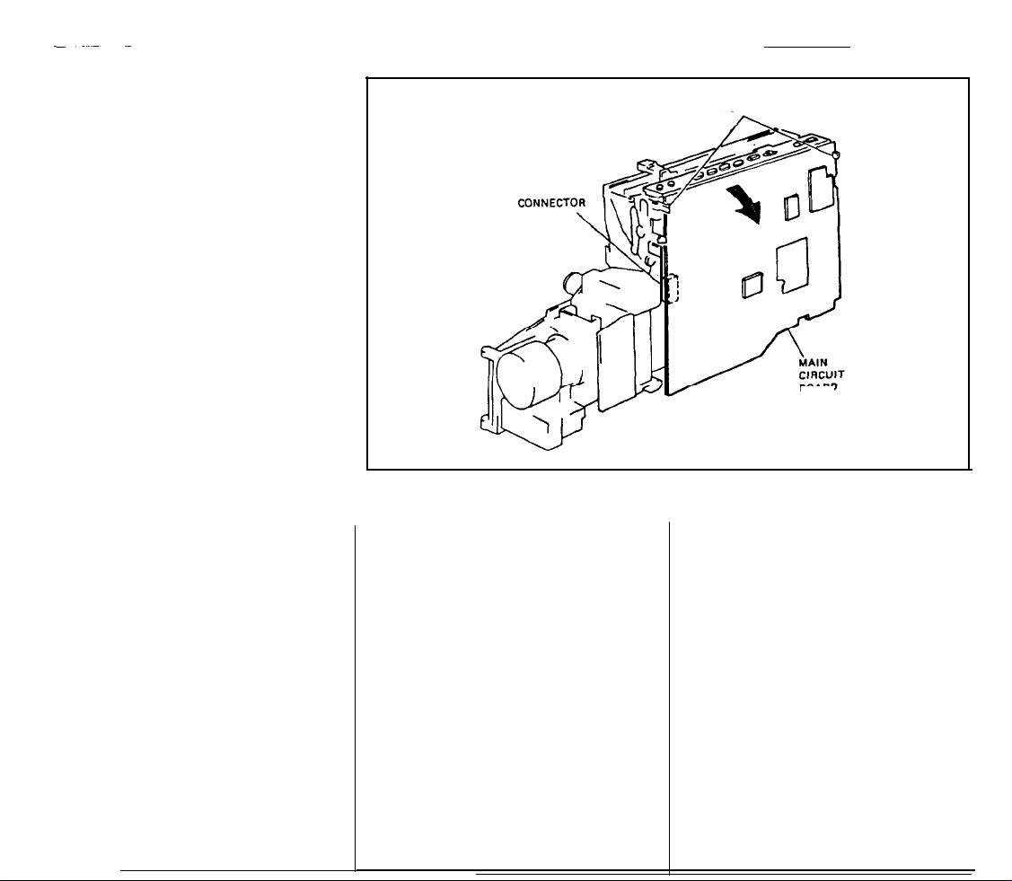
DISCONNECT
Figure 2. Jack circuit board removal
condition, because the lackofpulses from
the capstan and take-up sensors will alert
to order your parts from RCA instead of
ordering from Hitachi.
the system control microprocessor to
enter the protection mode, and the
cam-
corder will shut off.
If you have checked all of these func-
tions, and have determined that a belt may
need to be replaced; replace them all.
There are only three belts on the mech-
sense LED you put on earlier. Close the
cassette holder, (if you can). Unplug the
adapter cable to give yourself more room.
Unplug and remove the viewfinder.
anism, and since they were all manufac-
tured at the same time, if one is worn, the
other two can’t be far behind.
Belt part numbers 6356445, 6356472
and 6358012 should be available from
any Hitachi part distributor. Use numbers
cassette housing facing down, and the
lens assembly pointing to your left.
move the screws that hold the case shells
together. Next, carefully pull the shell
that’s facing you off and set it aside.
174757, 174758 and 174759 if you want
RELEASE
TWO TABS
BOARD
Getting to the belts
To begin, remove the covering from the
Lay the camcorder on its side, with the
Re-
Release the main pc board from the two

19.
Lower Cylinder
20. Mechanism State Switch
21.
Supply Loading
Cam
Gear
22. Take-up Loading Cam Gear
25.
Slider Arm
26.
PB/REC
27.Damper
28. Capstan Motor
23. Mode Motor and Belt 29. Capstan Flywheel
24.
Cam Gear
Figure 3. Tape transport mechanism- Bottom
white clips on both sides (Figure 2) and
slide the control pc board (buttons and all)
slowly toward you. Unplug the small connector from the bottom of the main pc
board, and remove the large wiring harness from its holder. This should allow
you to tilt the board for free access to the
tape mechanism.
Next, remove the plastic sheet covering the capstan pulley. Locate and remove
the screws and cover holding the flywheel
in place, and lift off the cover. Remove
the old belts and clean the gum deposits
off the pulleys with a solvent, such as alcohol or acetone.
vie
w.
inspect the area for wiring that may interfere with any movement of the mechanism. It’s a tight squeeze, but you can take
off the mode belt from the motor pulley
and worm gear pulley without removing
either one.
Located in the top left comer (Figure
3),
these pulleys should be cleaned too.
Again, make sure there are no twists or
excess grease on the new belt.
While you have the case off, it’s a good
idea to use a small soft brush to clean out
the dirt and dust that has found its way
inside. Reinstall the connector to the main
pc board, tuck the large wiring harness
back into its holder and slide the control
Replacing the belts
Replace the capstan belt, then the
tape-
wind belt. Rotate the flywheel by hand to
pc board into the slots on the top case.
Then snap the main pc board back into
the clips that hold it in place.
insure that there are no twists in the belts,
and remove any grease that may have
found its way onto the new belts.
Reinstall the flywheel cover and
screws. Reinstall the plastic sheet and
move the other side shell. Clean the video
heads, lower cylinder lip, guides, guide
The finishing touches
Next, turn the camcorder over and re-
Drive Arm
TOP EDGE
OF CHASSIS
rollers, pinchroller, ACE heads, impedance roller and capstan shaft with isopropyl alcohol (or other suitable chemical).
Always be extremely careful when
cleaning the video heads. Follow the
manufacturer’s directions carefully, and
use only specially made plastic foam or
chamois leather swabs.
Remove any excess grease and dirt
with Q-tips or a soft brush. Reinstall the
side shells and viewfinder.
Before powering up the camcorder,
clean the lens and viewfinder window
with a lens cleaning solution and lens tissue (available at any retail camera store).
Then connect the camcorder and TV (or
monitor) to the ac adapter and plug it in.
Slide the power switch to on, press eject
and put in a tape to test play quality. If
everything is in order, you should have a
clear picture on the screen and in the
viewfinder. Make sure that the audio is
playing back at the proper level and that
it is not distorted.
Perform a thorough operational test
Stop and eject your play test tape and
insert a tape you can record on. Remove
the lens cover and put the camcorder into
the record mode. While recording, use the
zoom, focus and other features on the
camcorder to verify that everything is
working properly, and that no connectors
are loose. Playback your recording and
check the video and sound for accurate
and natural qualities.
Because you didn’t disturb any electrical circuitry or tape path geometry, you
won’t need expensive jigs, charts or other
test equipment for a repairjob such as this.
Replacement of pc boards, power supply
components or the CCD and associated
parts would require a more involved repair
and adjustment procedure.
If, after a few belt and cleaning jobs,
you like the challenge that a camcorder
provides, there are books available from
Ryder Press, Howard Sams and others
that deal with camcorder theory and operation in full detail. Also, Philips of North
America, and others, have classroom
education on camcorder repair.
Camcorders manufactured in the 90’s
require more elaborate test jigs and contain exotic concepts never thought of in
the
80’s.
But isn’t the same true in other
areas of electronics?
n
62
Electronic Servicing & Technology November 1993
 Loading...