

HEIDENHAIN EIB 741, EIB 742 User Manual

July 2013
User’s Manual
EIB 741
EIB 742
External Interface Box
for Connecting
HEIDENHAIN Encoders

2
DOCUMENTATION ................................................................................................................................ 5
FIRMWARE VERSION ............................................................................................................................ 5
CHANGE HISTORY ................................................................................................................................. 5
PART 1: FEATURES ................................................................................................................................ 6
1 GENERAL DESCRIPTION OF FUNCTION .......................................................................................... 6
2 CONFIGURATION OF THE ENCODER INPUTS ................................................................................. 7
2.1 Processing Incremental Signals ............................................................................................................................ 7
2.2 Analog Values of the 1 VPP Incremental Signals A and B: ................................................................................. 9
2.3 Dealing with Reference Marks ............................................................................................................................... 9
2.4 Monitoring the Reference Marks ......................................................................................................................... 10
2.5 Processing EnDat Signals .................................................................................................................................... 11
2.6 Auxiliary Axis ........................................................................................................................................................ 14
3 PROCESSING OF TRIGGER EVENTS .............................................................................................. 15
3.1 Trigger Inputs and Outputs ................................................................................................................................. 15
3.2 Logical Inputs and Outputs .................................................................................................................................. 16
3.3 Trigger Module ..................................................................................................................................................... 16
3.4 Interval Counter .................................................................................................................................................... 18
3.5 Maximum Trigger Rate ........................................................................................................................................ 18
3.6 Counter for Accepted Trigger Events.................................................................................................................. 18
4 TIMESTAMP ...................................................................................................................................... 19
5 STATUS WORD ................................................................................................................................. 19
6 ETHERNET INTERFACE .................................................................................................................... 22
7 OPERATING MODES ........................................................................................................................ 22
7.1 Configuration of Data Packets ............................................................................................................................. 22
7.2 "Polling" Operating Mode .................................................................................................................................... 24
7.3 "Soft Real-Time" Operating Mode ...................................................................................................................... 25
7.4 "Streaming" Operating Mode .............................................................................................................................. 26
7.5 "Recording" Operating Mode .............................................................................................................................. 27
8 FIRMWARE UPDATE ......................................................................................................................... 28
9 RESET ................................................................................................................................................ 28
PART 2: DRIVER SOFTWARE .............................................................................................................. 29
1 GENERAL INFORMATION ................................................................................................................ 29
2 INSTALLATION INSTRUCTIONS ..................................................................................................... 29
2.1 Windows ................................................................................................................................................................ 29
2.2 Linux ...................................................................................................................................................................... 29
3 OVERVIEW ........................................................................................................................................ 29
3.1 Establishing Communication ............................................................................................................................... 29
3.2 Configuration of Data Packets ............................................................................................................................. 29
3.3 Polling Mode ......................................................................................................................................................... 30
3.4 Soft Real-Time Mode ............................................................................................................................................ 30
3.5 Streaming Mode ................................................................................................................................................... 30
3.6 Recording Mode .................................................................................................................................................... 30
4 DATA TYPES ..................................................................................................................................... 31
4.1 Simple Data Types ................................................................................................................................................ 31
4.2 EnDat Additional Datum ...................................................................................................................................... 31
4.3 Information for TCP Connection .......................................................................................................................... 31
4.4 Configuration for Data Packet ............................................................................................................................. 31
5 PARAMETERS AND RETURN CODES ............................................................................................. 31
6 AUXILIARY FUNCTIONS .................................................................................................................. 32
6.1 Determining the IP Address ................................................................................................................................. 32
6.2 Changing the Position Data Format .................................................................................................................... 32

3
7 DEVICE FUNCTIONS ......................................................................................................................... 33
7.1 Opening a Connection to the EIB 74x ................................................................................................................. 33
7.2 Closing the Connection to the EIB 74x ............................................................................................................... 34
7.3 Polling the Connection Status ............................................................................................................................. 34
7.4 Setting Up Timeout .............................................................................................................................................. 34
7.5 Reading Out the Number of Axes ....................................................................................................................... 35
7.6 Requesting Handle for Axis ................................................................................................................................. 35
7.7 Requesting IO Port Handle ................................................................................................................................... 35
7.8 Creating a Data Packet ......................................................................................................................................... 36
7.9 Configuring a Data Packet ................................................................................................................................... 36
7.10 Selecting the Operating Mode ............................................................................................................................ 37
7.11 Saving Network Parameters ................................................................................................................................ 37
7.12 Reading out the Network Parameters ................................................................................................................ 38
7.13 Saving the Host Name ......................................................................................................................................... 38
7.14 Reading out the Host Name ................................................................................................................................ 39
7.15 Reading out the Serial Number ........................................................................................................................... 39
7.16 Reading out the Device ID .................................................................................................................................... 39
7.17 Reading out the MAC Address ............................................................................................................................ 40
7.18 Reading out the Firmware Version Number ...................................................................................................... 40
7.19 Reading out the Boot Mode ................................................................................................................................. 41
7.20 Reading out the Update Status ........................................................................................................................... 41
7.21 Reading the Number of Open Connections ........................................................................................................ 41
7.22 Reading out the Connection Data ....................................................................................................................... 42
7.23 Terminating the Connection ................................................................................................................................ 42
7.24 Reading the Time Unit Timestamp ..................................................................................................................... 42
7.25 Setting the Timestamp Period Duration ............................................................................................................. 43
7.26 Resetting the Timestamp Counter ...................................................................................................................... 43
7.27 Reading the Timer-Trigger Time Unit ................................................................................................................. 43
7.28 Setting the Timer Trigger Period Duration ......................................................................................................... 43
7.29 Reading the Time Unit for the Delay Time at the Trigger Inputs ..................................................................... 44
7.30 Clearing the Trigger Counter ............................................................................................................................... 44
7.31 Software Trigger ................................................................................................................................................... 44
7.32 Selecting the Master Trigger Source .................................................................................................................. 45
7.33 Activating Trigger Sources .................................................................................................................................. 46
7.34 Configuring the Pulse Counter ............................................................................................................................ 47
7.35 Setting the Interpolation Factor for the Interval Counter ................................................................................. 48
7.36 Configuring the Interval Counter ........................................................................................................................ 49
7.37 Setting the Terminating Resistors ...................................................................................................................... 49
7.38 Reset ...................................................................................................................................................................... 50
7.39 Identifying the EIB 74x ......................................................................................................................................... 50
7.40 Transferring the Recording Data ......................................................................................................................... 51
7.41 Verifying the Recording Status ........................................................................................................................... 51
7.42 Reading the Recording Memory Size.................................................................................................................. 52
7.43 Checking the Streaming Status .......................................................................................................................... 52
7.44 Reading Data from the FIFO ................................................................................................................................ 53
7.45 Reading the Size of a FIFO Element .................................................................................................................... 53
7.46 Access to the Contents of a FIFO Element ......................................................................................................... 54
7.47 Reading and Converting Data from the FIFO ..................................................................................................... 55
7.48 Reading the Size of a FIFO Element Following Conversion .............................................................................. 55
7.49 Access to the Contents of a FIFO Element with Converted Data ..................................................................... 56
7.50 Reading the Number of Elements in the FIFO .................................................................................................... 56
7.51 Clearing the FIFO .................................................................................................................................................. 57
7.52 Setting the FIFO Size ............................................................................................................................................ 57
7.53 Reading the FIFO Size .......................................................................................................................................... 57
7.54 Activating the Callback Mechanism .................................................................................................................... 58
7.55 Selecting the Trigger Source for the Auxiliary Axis .......................................................................................... 59
7.56 Reading the Position of the Auxiliary Axis ......................................................................................................... 59
7.57 Reading Out the Data of the Auxiliary Axis ........................................................................................................ 60
7.58 Clearing the Counter of the Auxiliary Axis ......................................................................................................... 60
7.59 Acknowledging the Signal Errors of the Auxiliary Axis .................................................................................... 60
7.60 Acknowledging the Trigger Errors of the Auxiliary Axis ................................................................................... 61
7.61 Clearing the Status Bit for the Reference Mark of the Auxiliary Axis .............................................................. 61
7.62 Checking the Status of the Reference Run for the Auxiliary Axis .................................................................... 61

4
7.63
Starting a Reference Run for the Auxiliary Axis ................................................................................................ 61
7.64 Stopping a Reference Run for the Auxiliary Axis ............................................................................................... 62
7.65 Configuring a Timestamp for the Auxiliary Axis ................................................................................................ 62
7.66 Setting the Trigger Edge for the Reference Pulse of the Auxiliary Axis .......................................................... 62
8 AXIS FUNCTIONS ............................................................................................................................. 63
8.1 Initializing the Axis ............................................................................................................................................... 63
8.2 Selecting the Trigger Source for the Axis .......................................................................................................... 66
8.3 Setting the Trigger Edge for the Reference Pulse ............................................................................................. 66
8.4 Clearing the Counter ............................................................................................................................................ 67
8.5 Interrogating a Position ....................................................................................................................................... 67
8.6 Reading out Data for a Channel .......................................................................................................................... 68
8.7 Acknowledging the Power Supply Error ............................................................................................................ 68
8.8 Acknowledging the Trigger Error ........................................................................................................................ 69
8.9 Acknowledging the Signal Error ......................................................................................................................... 69
8.10 Clearing EnDat Error Bits ..................................................................................................................................... 69
8.11 Clearing Status Bits for Reference Marks ........................................................................................................... 70
8.12 Clearing Status Bits for Distance-Coded Reference Marks ............................................................................... 70
8.13 Starting the Reference Run .................................................................................................................................. 70
8.14 Stopping the Reference Run ................................................................................................................................ 71
8.15 Verifying the Status of the Reference Run ......................................................................................................... 71
8.16 Activating the Monitoring of the Reference Marks ........................................................................................... 71
8.17 EnDat 2.1: Reading the Position .......................................................................................................................... 72
8.18 EnDat 2.1: Selecting the Memory Area ............................................................................................................... 72
8.19 EnDat 2.1: Sending Data ...................................................................................................................................... 73
8.20 EnDat 2.1: Receiving Data .................................................................................................................................... 73
8.21 EnDat 2.1: Resetting the Encoder ........................................................................................................................ 74
8.22 EnDat 2.1: Reading the Test Value ...................................................................................................................... 74
8.23 EnDat 2.1: Sending Test Command to Encoder ................................................................................................. 75
8.24 EnDat 2.2: Reading the Position and Additional Datum .................................................................................... 75
8.25 EnDat 2.2: Reading the Position and Additional Datum and Selecting the Memory Area ............................. 76
8.26 EnDat 2.2: Reading the Position and Additional Datum and Sending Data .................................................... 76
8.27 EnDat 2.2: Reading the Position and Additional Datum and Receiving Data .................................................. 77
8.28 EnDat 2.2: Reading the Position and Additional Datum and Sending the Test Command ............................ 77
8.29 EnDat 2.2: Reading the Position and Additional Datum and Transmitting the Error Reset ........................... 78
8.30 EnDat 2.2: Selecting the Additional Datum ........................................................................................................ 79
8.31 EnDat 2.2: Selecting the Sequence for Additional Datum ................................................................................ 80
8.32 Reading Absolute and Incremental Position Values Simultaneously .............................................................. 81
8.33 Setting the Power Supply for Encoders ............................................................................................................. 81
8.34 Reading the Power Supply Status for Encoders ................................................................................................ 82
8.35 Configuring the Timestamp ................................................................................................................................. 82
9 IO FUNCTIONS .................................................................................................................................. 83
9.1 Configuring the Input Port ................................................................................................................................... 83
9.2 Configuring the Output Port ................................................................................................................................ 84
9.3 Selecting the Trigger Source for the Trigger Output ........................................................................................ 84
9.4 Setting the Delay Time for the Trigger Input ..................................................................................................... 85
9.5 Reading Out a Logical Port .................................................................................................................................. 85
9.6 Setting the Logical Output Port .......................................................................................................................... 86
9.7 Reading the Configuration Data for an Input ..................................................................................................... 86
9.8 Reading the Configuration Data for an Output .................................................................................................. 87
10 GENERAL FUNCTIONS ................................................................................................................... 88
10.1 Reading the Driver ID Number ............................................................................................................................ 88
10.2 Converting an Error Message into Text .............................................................................................................. 88

5
Documentation
The documentation for the EIB 741 and EIB 742, hereafter referred to as EIB 74x, comprises the following documents:
• Commissioning Instructions:
- Documents required for commissioning, as well as technical specifications.
• User's Manual:
- Description of features on the EIB 74x.
- Description of the installation and function calls of the driver software.
Firmware version
This document describes Firmware version: 633281-10
Change history
Changes from the previous versions are listed in the change history.
The document on change history is on the CD in the subdirectory EIB_74x/doc. Please read this document, in particular the
notes on new, changed or obsolete function calls.

6
Part 1: Features
1 General Description of Function
The EIB 74x is an external interface box for precise position measurement. It is ideal for inspection stations and multipoint
inspection apparatuses as well as for mobile data acquisition, such as in machine inspection and calibration.
The EIB 74x is ideal for applications requiring high-resolution encoder signals and fast data logging. Ethernet transmission
also enables you to use switches or hubs for connecting more than one EIB 74x.
A maximum of four HEIDENHAIN encoders, either with sinusoidal incremental signals (1 V
PP
) or with EnDat interfaces
(EnDat 2.1 and EnDat 2.2) can be connected to the EIB 74x.
The EIB 74x subdivides the periods of the incremental signals 4096-fold for measured-value generation. The deviations
within one signal period are automatically reduced by adjusting the sinusoidal incremental signals (signal compensation).
The integrated measured-value memory enables the EIB 74x to save up to 250,000 measured values per axis in "recording
mode." Internal or external triggers can be used for axis-specific storage of the measured values. A standard Ethernet
interface using TCP or UDP communication is available for data output. This permits direct connection to a PC, laptop or
industrial PC.
The method of measured value transmission can be set via the operating mode. Driver software for Windows, Linux and
LabVIEW is included in the items supplied, in order to process the measured values on the PC. The driver software facilitates
programming of customer applications. It also contains program examples demonstrating the performance range of the
EIB 74x.
Basic circuit diagram
Encoder inputs:
A maximum of four HEIDENHAIN encoders with the following interfaces (freely programmable) can be connected to the
EIB 74x:
• Incremental signals 1 V
PP
• EnDat 2.1
• EnDat 2.2
• Incremental signals 1 V
PP
(upon request)
The power supply to the encoders is provided by the EIB 74x and is protected by a resettable overload cutout.
For technical specifications, see "Commissioning Instructions."

7
2 Configuration of the Encoder Inputs
After power-up, the power supply to the encoders is activated. The other parameters for operating the encoder input must
be configured by initialization.
• Interface type
• Bandwidth for the 1 V
PP
input signals
• Signal compensation
• Processing the reference marks
• Processing the homing/limit signals
These settings can be changed via software.
The interface for the encoder input can be operated in incremental or EnDat mode. In EnDat mode, the incremental block
can also be operated if, in addition to EnDat, the encoder also supports the 1 V
PP
interface.
2.1 Processing Incremental Signals
The EIB 74x subdivides the periods of the incremental signals 4096-fold for position value generation (12 bits). The period
counter has a width of 32 bits. The counter value is increased or decreased by the value "1" with each signal period of the
connected encoder.
The deviations within one signal period are automatically reduced by adjusting the sinusoidal incremental signals (signal
compensation). Compensation of the incremental encoder signals and the terminating resistor can be activated or
deactivated by software.
The 44-bit wide position information at the time of the trigger event is formed from the interpolation value (12 bits) and the
value of the period counter (32 bits). The position information is saved to a 48-bit wide register (see table). The period
counter is mapped in the two's complement notation; bits 43 to 47 represent the sign.
Depending on the encoder type (linear or rotary), the higher-level customer software application can use this value to
calculate the angle and length, respectively.
The period counter overflows according to the two's complement notation at the position: 0x07FF FFFF FFFF (maximum
positive) 0xF800 0000 0000 (maximum negative). This overflow does not affect the functionality of the period counter or
the interpolator. The overflow, however, must be handled by the higher-level customer software application.
Bit no. Width (bits) Contents
0..11 12 Interpolation value
12..43 32 Period counter (bit 43 = sign)
44..47 4 Value identical to bit 43

8
Block diagram
Interpolation value
At the time of the trigger event, the incremental signals are scanned and used to calculate a 12-bit wide interpolation value
(not with the EnDat interface). The correlation between interpolation value and incremental signals is derived as follows:
Setting options:
Terminating resistor for the incremental signals
The 120 ohm terminating resistor for the 1 V
PP
incremental signals can be activated or deactivated (for all channels
simultaneously; default: resistors activated) by software.
Bandwidth setting of the incremental signals
The bandwidth of the encoder's incremental signals can be toggled by software. The high bandwidth (500 kHz) should be set
as default.
The low bandwidth (33 kHz) should only be selected for special applications.
Signal compensation
Compensation of the incremental encoder signals can be activated or deactivated by software.
9
2.2 Analog Values of the 1 V
PP
Incremental Signals A and B:
The transmitted values correspond to the values of the AD converter at the time of the trigger event.
Bit no. Width (bits) Contents
0..11 12 12-bit AD converter value
12..15 4 Reserved
Value (HEX) Incremental signal value
000 Negative maximum
800 Zero
FFF Positive maximum
2.3 Dealing with Reference Marks
With incremental encoders, the reference mark/marks is/are used to generate an absolute reference for the incremental
signals.
For encoders with one reference mark, this mark has an explicit reference to a specific signal period. This signal period can
be used as a reference to generate absolute position values. Traversing the reference mark does not affect the period
counter or the interpolation value. The period counter value valid at the time of traversing is simply saved in a register for the
reference position. This value can be used in the customer software application to calculate absolute position values.
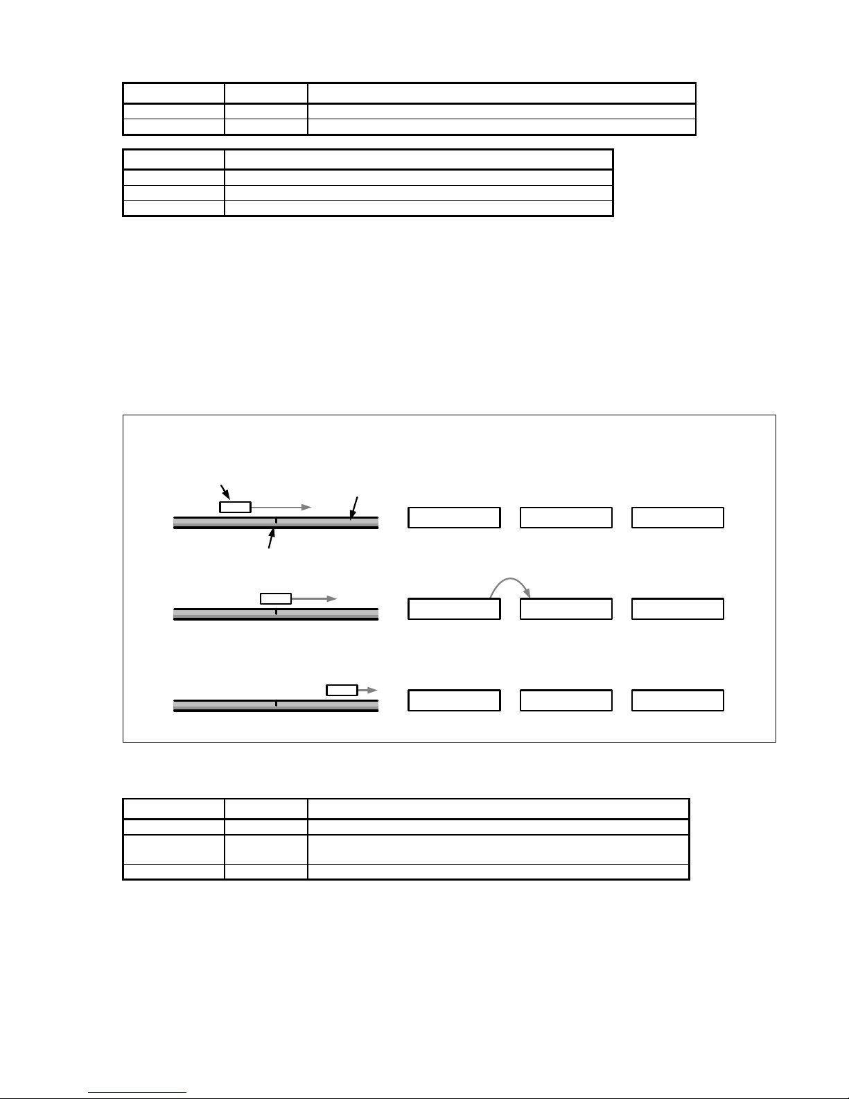
The figure below shows the general process of determining a reference position. The displayed values are only given as an
example. To improve clarity, only a section of the position-value register is shown.
Linear scale
Scanning head
Reference mark
Motion
0x2A733D1
Actual position
value
Stored reference
position
Absolute position
(calculated by the
application)
0x318B000
0x36D9884
0x318B000
0x318B000
0x0000000
0x054E884
-
=
-
-
=
=
latch
Reference mark detected
Register contents, reference position
Bit no. Width (bits) Contents
0..11 12 Always 0
12..43 32
Reference position (value of the period counter when the reference
mark is detected; bit 43 = algebraic sign)
44..47 4 Value identical to bit 43
Automatic saving of the reference position must be activated by software. After this command, the EIB 74x waits for the
next reference mark and then saves the reference position.
You must activate this feature again if renewed saving is desired.
Normally, the reference position register is transmitted together with the position register and the status word in a shared
position data packet after the next trigger event. During this process, the EIB 74x transmits two reference positions and,
where applicable, the coded reference value:
• For encoders with one reference mark, reference position 1 is normally used.
• For encoders with distance-coded reference marks, either both register values are used or the coded reference
value is used depending on the evaluation method.

10
Distance-coded reference marks
With distance-coded encoders, the reference for generating absolute position values from the counter values is obtained
through the distance of two traversed (adjacent) reference marks.
For this purpose, the period counter value is saved twice, once each time a reference mark is traversed. The coded
reference value is generated from the distance of the (adjacent) reference marks, and in doing so the reference for
generating absolute position values is also created.
When the absolute position value is calculated by the customer software application, this value is treated exactly the same
as a saved reference position value in the case of encoders with one reference mark (see drawing). The coded reference
value thus corresponds to the offset between the absolute position value and the generated (incremental) position value.
There are various procedures for generating the coded reference value:
Method 1: (recommended method)
The axis is initialized as an incremental system with distance-coded reference marks. During this process, further typedependent information about the measuring system is transferred to the EIB 74x. Once the reference positions have been
saved successfully, the EIB 74x uses this information to automatically calculate the coded reference value. The saving
process is started by software command (for two reference marks). After the second reference mark has been traversed,
the EIB 74x automatically calculates the coded reference value and transfers it to the customer software application.
Method 2: (especially for applications with an extremely low traversing speed)
The axis is initialized as an incremental system with a simple reference mark. The customer software application sends the
appropriate software command for saving the reference position (one reference mark). Each time the reference position has
been saved successfully, the save process is activated again. This procedure must be repeated until two different reference
positions have been measured. The customer software application can then calculate the coded reference value and hence
the absolute position from these two values. It must be guaranteed that the customer software application can complete this
procedure quickly and sufficiently, otherwise reference marks could be lost, resulting in an incorrect calculation of the
absolute position.
Method 3:
The axis is initialized as an incremental system with a simple reference mark. The customer software application sends the
appropriate software command for saving two reference positions. After both reference positions have been saved
successfully (both reference position registers are used), the customer software application can calculate the coded
reference value and hence the absolute position from these two values.
2.4 Monitoring the Reference Marks
The reference marks of an encoder can be monitored automatically. For this purpose, the reference position is saved and
checked continuously. This results in the reference-position output being updated with each reference mark, and therefore
can lead to a change in the reference position. The check varies slightly depending on the encoder, as described below. If an
error occurs, a bit is set in the status word for the position.
Encoders with one reference mark:
For linear encoders with one reference mark, the position value at the reference mark must always be the same. The
reference position is saved continuously and compared to the old value.
For rotary encoders with one reference mark, the position value at the reference mark may change if the encoder is moved
in the same direction over one revolution. Two successively saved reference positions must be the same or may differ by
the number of signal periods per revolution. The transmitted data packet always contains the current reference position.
Encoders with distance-coded reference marks:
For encoders with distance-coded reference marks, the coded reference position is recalculated continuously. The
calculation always uses two adjacent reference positions as illustrated in the figure below. The transmitted data packet
always contains the currently calculated reference position.

11
For linear encoders, the calculated reference position must always be the same. For rotary encoders, the calculated
reference position may differ by the number of signal periods per revolution. If the same reference mark is traversed twice
before and after a change in direction, the distance-coded reference mark cannot be calculated. No check takes place in this
case. This must be taken into account especially for very small movements across a reference mark.
No reference run can be performed while monitoring of the reference marks is active, because this could lead to an incorrect
error message in the monitoring process. The following sequence is recommended:
• Configuring the axes
• Performing the reference run
• Activating the monitoring of the reference marks
2.5 Processing EnDat Signals
HEIDENHAIN absolute encoders are available with EnDat 2.1 or EnDat 2.2 interface. Especially in the case of EnDat 2.1
encoders, 1 V
PP
incremental signals are transmitted along with the EnDat signals. The EIB 74x is able to process all EnDat
encoders with EnDat 2.1 or EnDat 2.2 interface both serially and also with 1 V
PP
incremental signals.
The EnDat Master is set up individually when the axis is initialized:
• EnDat 2.1 or EnDat 2.2 communication can be set.
• The clock frequency for EnDat communication can be set.
• Delay compensation (EnDat 2.2) can be activated or deactivated.
• The recovery time I can be set if the encoder supports it.
• The monitoring of the calculation time can be set.
Notes on EnDat 01:
• If EnDat position polls and 1 V
PP
incremental signals are used at the same time, only EnDat 2.1 mode commands
can be sent to the encoder (axis must be configured for EnDat 01).
• The EnDat position can be imported only by a software command. Hence, the EnDat position and incremental
position must be imported once (special command). Then an incremental position can be cyclically transferred.
Position value register
The position register maps the position transmitted via the EnDat interface at the time of the trigger event. The position
register for the EnDat position is 48-bits wide. The number of bits used for the position value depends on the connected
EnDat encoder; the uppermost, unused bits must be masked out. See the encoder specifications for more detailed
information.
Bit no. Width (bits) Contents
0..47 48 EnDat position value

12
EnDat clock frequency
The EnDat clock frequency can be set by a software command. The clock frequency can be set at specific intervals between
100 kHz and 6.66 MHz. The maximum permitted frequency is dependent on both the cable length between encoder and
EIB 74x and also on whether delay compensation is activated.
Clock frequency
parameter
Clock frequency Comment
100000 100 kHz
300000 300 kHz Default with EnDat 2.1
500000 500 kHz
1000000 1 MHz
2000000 2 MHz Default with EnDat 2.2
4000000 4 MHz
5000000 5 MHz
6666666 6.66 MHz
Delay compensation
Delay compensation for the EnDat transmission can be activated or deactivated during axis configuration. Delay
compensation is not approved by HEIDENHAIN for EnDat 2.1 encoders (exception: encoders with the ordering designation
EnDat21). Delay compensation is approved by HEIDENHAIN for EnDat 2.2 encoders. This results in the following
dependency of the maximum permitted EnDat clock frequency.
EnDat clock frequency
Cable length in meters
Without delay compensation With delay compensation
100 kHz 150 100
300 kHz 150 100
500 kHz 100 100
1 MHz 55 100
2 MHz 10 100
4 MHz --- 50
5 MHz --- 40
6.66 MHz --- 25
Recovery time I
The recovery time I can be set for EnDat 2.2 encoders (ordering designation EnDat02 or EnDat22). Here there are two
options—"long" (10 µs < t
m
< 30 µs) and "short" (1.25 µs < tm < 3.75 µs). For EnDat 2.1 encoders, the long recovery time I is
always used.
Notes on setting the short recovery time I:
• The default setting is "long."
• The short setting is chosen in order to attain shorter cycle times during EnDat transmission.
• For the short setting, the EnDat clock frequency must be set to > 1 MHz at the same time.
Calculation time
The calculation time indicates the time for position formation in the encoder and therefore affects the duration of the position
request. In order to monitor the communication a timeout is generated if the position request exceeds a certain duration.
This is displayed in the status word as an error. If the calculation time was set too short, this error message can appear even
though the encoder transmitted the data correctly. Conversely, an excessively long calculation time can cause an undesired
delay in the error message. At high trigger rates, in particular, the error message can be offset by several samples.
The calculation time can be set to depend on the connected encoder. Two options are supported:
Long The calculation time of the encoder is < 1 ms
Short The calculation time of the encoder is < 15 µs
Notes:
• The default setting is "long."
• For the short setting, the EnDat clock frequency must be set to > 1 MHz at the same time.

13
EnDat 2.2 additional data
The EnDat 2.2 additional data can be transmitted in various ways in the Soft Real-Time, Streaming, and Recording operating
modes.
1) No additional datum
A position request is started with each trigger event. Additional data is not transmitted.
2) Fixed additional data
Besides the position value, with each trigger event one piece of fixed information is sent as additional datum 1 and additional
datum 2. This has to be set before activation of the corresponding operating mode. It can only be changed in the Polling
mode of operation. It is also possible to transmit only additional datum 1 or additional datum 2.
3) Variable additional data
The additional data is switched in cycles. The EIB 74x features a ring buffer with 10 entries for setting the additional data,
which is executed cyclically. The position value and the additional data 1 and 2 are transmitted with each trigger event. In
addition, the EnDat 2.2 transmission supplement is transmitted, over which a new additional datum is selected based on the
data in the ring buffer. The additional data 1 and 2 can be mixed in the ring buffer. Only one of the two additional data can be
switched over per position request.
Processing additional incremental signals with EnDat
If, with EnDat encoders, the incremental signals are used for position formation, an absolute reference can be created by
saving the EnDat position and the incremental position simultaneously. To do this, a special command is sent to the EIB 74x
via the customer software application, which then generates an internal trigger signal. This trigger signal initiates
simultaneous position determination via the EnDat interface and via the incremental signals. Both positions are transmitted
to the customer software application as a return code.
Note:
The interpolation zero points for the incremental signals and the EnDat position are different and must also be taken into
account by the customer software application.
Furthermore, any differing resolution between EnDat and incremental position must also be taken into account.
Incremental signals: see "Processing incremental signals" section for interpolation zero point
EnDat Position: see graphic for interpolation zero point
EnDat master

14
2.6 Auxiliary Axis
The auxiliary axis is coupled to axis 1 and can be used for encoders with 1 Vpp interface. The signals of axis 1 are
interpolated and forwarded to a position counter. The interpolation factor can be set at specific intervals. Edge evaluation (1fold, 2-fold or 4-fold) can also be selected. The maximum permissible input frequency of the encoder signals for the
interpolator depends on the interpolation factor and is shown in the table below. In order not to limit the input frequency
unnecessarily, the edge evaluation should be set to 4-fold (4x), and therefore a low interpolation factor should be selected.
For example, a 5-fold interpolation factor with 4-fold edge evaluation results in the same increment as a 20-fold interpolation
factor with 1-fold edge evaluation, but the maximum permissible input frequency is higher.
Linear encoder:
µm
=
µm
∙
Rotary encoder:
1°
=
360°
∙
Interpolation factor Max. input frequency in kHz
1-fold 500
2-fold 500
4-fold 500
5-fold 500
10-fold 400
20-fold 200
25-fold 160
50-fold 80
100-fold 40
Besides the position value, a timestamp and a reference position are available to the auxiliary axis. The status word for the
auxiliary axis contains status and error messages. Both the position value and the reference position are 32-bit values. The
number of counting steps per signal period of the encoder depends on the interpolation factor for the auxiliary axis. The
position value is represented as a two's complement number. According to this, it overflows at the position: 0x7FFF FFFF
(maximum positive) 0x8000 0000 (maximum negative). Any overflow must be handled by the higher-level customer
software application.
Bit no. Width (bits) Contents
0..31 32 Position value of the auxiliary axis (bit 31 = sign)
15
3 Processing of Trigger Events
Position value determination inside the EIB 74x is initiated via a so-called trigger event. The EIB 74x supports the following
trigger sources:
• 4 external trigger inputs
• Internal periodic trigger source, timer-controlled
• Software command
• Reference pulse of the encoders
• Position trigger (interval counter)
The trigger source must be set by software command for each axis; only one trigger source per axis can be active at the
same time. However, it is possible to activate different trigger sources for different axes. Also, one trigger source must be
defined as the master trigger source that defines the time of data transmission. For all axes triggered by the master trigger
source, a new position is transmitted in each data packet. For all other axes, a valid position is transmitted only if a trigger
event also occurred for the respective axis. Otherwise, the position value is marked as invalid.
Not all trigger interface options are supported in all operating modes; see "Operating Modes" section for details.
3.1 Trigger Inputs and Outputs
Four trigger inputs and/or outputs are supported. For technical specifications on the trigger input, see "Commissioning
Instructions."
Trigger inputs
Synchronize the position requests on external events; please also note the information provided in Chapter 3.5.
The 120 ohm terminating resistor can be activated or deactivated by configuration.
Trigger outputs
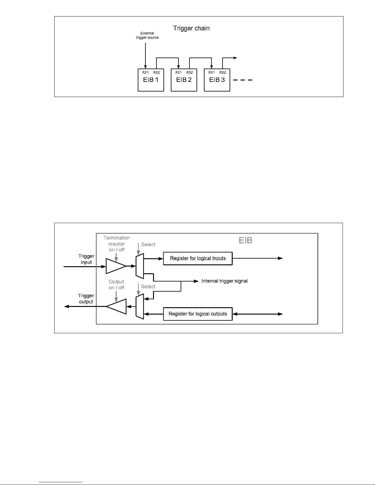
The trigger outputs forward trigger events, e.g. to other EIB 74x units. This permits the generation of a trigger chain, which
synchronizes multiple EIB 74x units with an external trigger event. The various EIB 74x units must be configured separately
by software commands. The position data is sent via the respective Ethernet connection. To generate a trigger chain, the
following connection between the EIB 74x units must be used:
• Trigger Out + Trigger In +
• Trigger Out – Trigger In –
• GND to GND
A pulse at the trigger output is 2 µs long and is generated synchronously with the system clock of the EIB 74x. The trigger
event corresponds to the rising edge of the pulse. If a signal is forwarded from the trigger input to the output, it is affected
by jitter due to the synchronization with the system clock. In order to avoid this jitter, it is possible to switch the signal at the
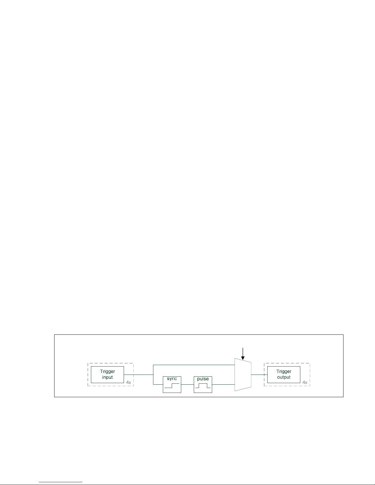
trigger input directly to the corresponding trigger output.
The trigger signals can be fed through from the input to the output separately for each channel. Input 1 can be connected to
output 1, and so on. The trigger input and the corresponding output are shown in the figure below.
Note:
The differential signals "Trigger Out +" and Trigger Out –" can be swapped in order to change the polarity of the signal at the
trigger output. Accordingly, the output "Trigger Out –" must be used for single-ended signals (see instructions for
installation/commissioning).
config
16
Configuring the trigger inputs and outputs as logical inputs and outputs
The trigger inputs/outputs can also be used as logical inputs/outputs. Trigger inputs and/or outputs are set by default. The
ports can be individually configured as logical inputs and outputs or as trigger inputs and outputs by a software command. It
is not possible to use them simultaneously as trigger inputs/outputs and logical inputs/outputs.
3.2 Logical Inputs and Outputs
Logical inputs
Each trigger input can be individually converted to a logical input. The level of the corresponding input can be read by a
software command. The 120 ohm terminating resistor can also be activated or deactivated in this mode by configuration.
Logical outputs
Each trigger output can be individually converted to a logical output. The output level can also be read back. The outputs can
be individually activated or deactivated, irrespective of the configuration.
The graphic below shows the trigger input and output options at a glance. Only one channel is shown.
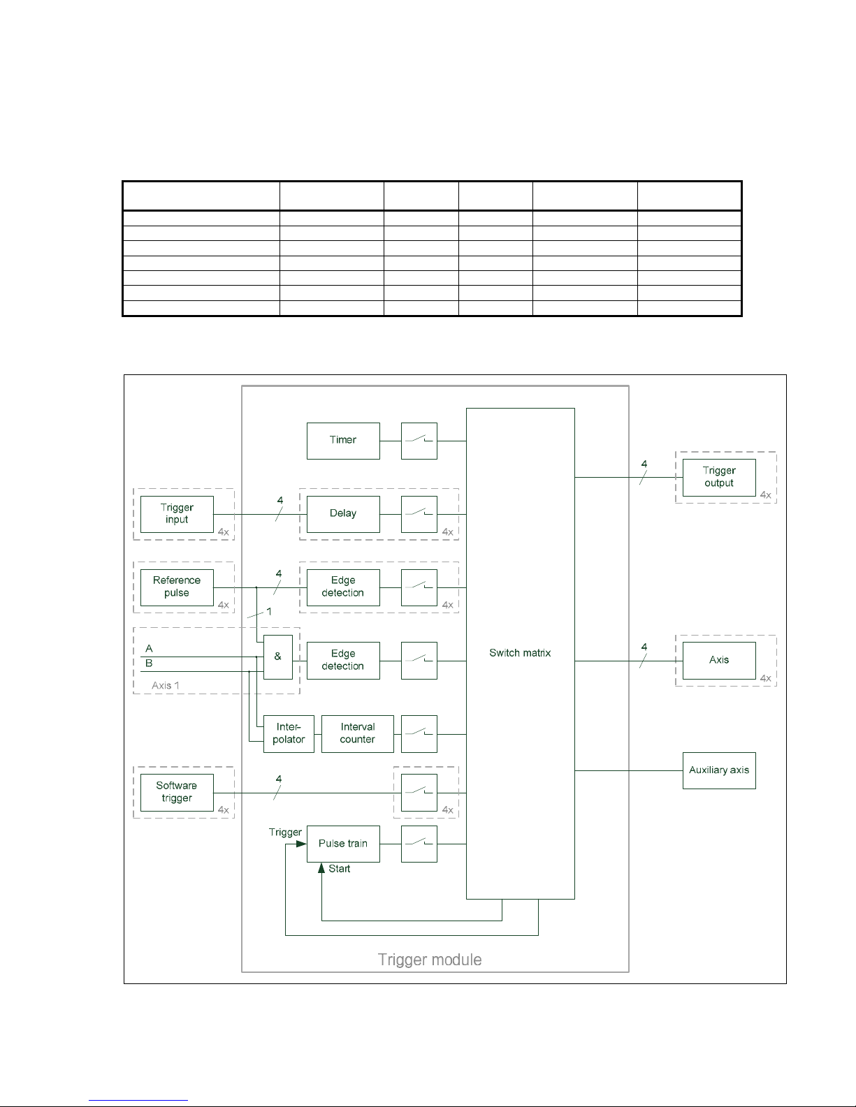
3.3 Trigger Module
The trigger module enables you to select and control the trigger sources. Furthermore, it generates internal trigger signals.
You can delay external trigger signals; the delay time can be set for each input separately. The reference pulse of an encoder
with 1 Vpp interface can be used for the associated axis as a trigger source. In addition, the reference pulse of axis 1 is gated
with the signals A and B of axis 1 by logic AND, and can be used as a trigger signal for any axes. The active edge of the
reference signal can be set in each case. If the reference pulse is selected as the trigger source for more than one axis, each
axis is triggered with its own reference pulse. If the reference pulse is also selected as the master trigger source in this
case, a reference pulse must occur on each axis before transmitting the data packet. Furthermore, there are four freely
assignable channels for software triggers.
The interval counter generates trigger signals depending on the position of the encoder on axis 1. A signal period of the
encoder can be divided into several counting steps via an adjustable interpolator. The triggering occurs either at a certain
position or at equidistant intervals.
17
The pulse counter is not a separate trigger source; it allows you to limit the number of trigger pulses of other sources. A
selectable trigger source can supply pulses that are disabled until the gate is opened by the start signal. All trigger pulses are
then counted, and the gate is closed again after a selectable number of pulses. Besides, it is possible to reload the counter
while the gate is open. The number of trigger pulses can be increased in this way.
The switch matrix makes it possible to connect the trigger sources individually to the sinks, such as trigger outputs or axes.
However, not all sources can be connected to all sinks. The following table provides an overview of the possible
combinations: Only one trigger source is permissible per sink. For the pulse counter, there is a trigger signal whose trigger
pulses are controlled via the internal gate. The start signal opens the gate for the trigger pulses.
Trigger source Trigger output Axis
Auxiliary
axis
Pulse-counter
trigger
Pulse-counter
start
Trigger input x x x x x
Reference pulse – x x x x
Masked reference pulse x x x x x
Interval counter x x x x x
Pulse counter x x x – –
Software trigger x x x – x
Timer x x x x –
All trigger sources can be deactivated separately. This makes it possible to first configure the EIB 74x and then enable the
trigger sources. Any combination of trigger sources can be enabled or disabled at the same time.

18
3.4 Interval Counter
The interval counter permits position-dependent triggering in connection with an incremental encoder on axis 1. The encoder
signal can be interpolated (see "Auxiliary Axis" chapter).
The triggering occurs at a certain position, or equidistant trigger pulses with an adjustable position interval are generated.
Output of the trigger pulses starts after an adjustable start position has been traversed, and is then continued at the position
interval in both counting directions. The position interval ΔX must be specified in counting steps (for calculating the
increment, see "Auxiliary Axis" chapter).
Hysteresis prevents multiple triggering, in particular if a high interpolation factor is used for the encoder signal. After a trigger
pulse has been generated at a position, the value of the position counter must change by +H or ---H before a new trigger
pulse is generated at the same position.
3.5 Maximum Trigger Rate
The maximum trigger rate of the EIB 74x depends on the set operating mode ("Polling" mode being an exception):
• Soft Real-Time mode: Max. 10 kHz
• Recording mode: Max. 50 kHz
• Streaming mode: Max. 50 kHz
Note:
In Streaming mode the data rate is additionally limited to 1 200 000 bytes/second. The data rate is product of the size of the
data packet and the trigger rate.
Byte
∙
Hz
≤ 1.200.000
Here it must be ensured that the data rate is not limited by the host on which the data are subsequently processed.
A certain interval, which the EIB 74x requires for the position calculation, must be respected between two trigger events. If
this interval is not respected, i.e. the trigger rate is too high, trigger events cannot be accepted by the EIB 74x, and therefore
are lost (lost trigger). This is detected by the EIB 74x and displayed in the status word of the position data packet by the "lost
trigger" bit. This bit is set at "1" until actively reset by the customer software application using a clear command.
The values mentioned above apply if incremental signals are used. If the EnDat interface is used, the EnDat transmission
time must be observed.
Caution:
If the maximum trigger rate is grossly exceeded (e.g. incorrect parameterization or too many events at the external trigger
input), this may result in the EIB no longer reacting to external commands so that it cannot be addressed until a hard reset.
3.6 Counter for Accepted Trigger Events
In addition to monitoring for lost triggers, the EIB 74x has, for further error detection, a counter that is incremented by each
incoming and accepted trigger event of the master trigger source. A trigger event is accepted if the above-mentioned interval
is maintained. Trigger events that result in lost triggers are not counted. The counter value is transferred in the position data
packet and can be monitored for continuity. This makes it possible to detect lost position data packets.
ΔX
ΔX

19
4 Timestamp
The "timestamp" function is also used to monitor data flow. The timestamp counter is a free-running timer with a freely
programmable time interval. Each trigger event that results in a position value determination also causes the current timer
value to be saved to the timestamp register. When the timestamp function is activated, the contents of this register are
transmitted with the position data packet. This enables the customer software application to check whether the latch time of
each individual position value corresponds to the expected value. In the case of applications that do not have a periodic
trigger, the time of the trigger event can be transmitted with this register.
Note:
The time interval of the counter timestamp is a multiple of the internal system clock in the EIB 74x. Before the timestamp
function can be used, the time interval has to be set by a software command. The "clock ticks per µs" value must first be
read and the required time interval set in dependence of this value. This is necessary to keep the software compatibility
independent of various settings for the system clock.
Note:
The following data must be transferred to the function to ensure that the value for a period (e.g. for the “period” parameter
of the “EIB7SetTimestampPeriod” function call) is correctly calculated:
period = Time interval in µs * clock ticks per µs
The value for “clock ticks per µs” can be read out using the EIB7GetTimerTriggerTicks or EIB7GetTimestampTicks function,
for example.
This note applies to the function call in Chapter 7.25, as well as for the calls in Chapter 7.28 (please also note Chapter 3.5)
and Chapter 9.4.
5 Status Word
The status word must be interpreted depending on the poll type:
• Incremental position data
• EnDat position data
• Polling of EnDat additional data
The status word is transmitted separately for each encoder channel and does not depend on which operating mode is set.
Bit no. Incremental position EnDat position EnDat additional datum Auxiliary axis
0 1 = Valid position 1 = Valid position 1 = Valid additional datum 1 = Valid position
1 1 = Signal amplitude error 1 = CRC error 1 = CRC error 1 = Signal amplitude error
2 Reserved Reserved Reserved Reserved
3 1 = Frequency exceeded Reserved Reserved 1 = Frequency exceeded
4
1 = Encoder power supply
error
1 = Encoder power supply
error
Reserved
1 = Encoder power supply
error
5 1 = Fan error 1 = Fan error Contents I0 1 = Fan error
6 Reserved Reserved Contents I1 Reserved
7 1 = Lost trigger 1 = Lost trigger Contents I2 1 = Lost trigger
8
1 = Reference position 1
saved
1 = EnDat error message 1 Contents I3
1 = Reference position
saved
9
1 = Reference position 2
saved
1 = EnDat error message 2 Contents I4 Reserved
10
1 = Coded reference value
for distance-coded
reference marks is valid
Reserved EnDat busy bit Reserved
11
1 = Error when calculating
the coded reference value
for distance-coded
reference marks. Error while
monitoring the reference
marks
Reserved EnDat RM Bit Reserved
12 1 = Homing signal active Reserved EnDat WRN bit Reserved
13 1 = Limit signal active Reserved Reserved Reserved
14 Reserved Reserved Reserved Reserved
15 Reserved Reserved Reserved Reserved

20
Notes on the error bits
Name Meaning
Valid position
1 No error occurred
This bit indicates whether the transmitted position is valid or not
Valid additional datum
1 EnDat additional datum was received
Otherwise, no additional datum has been selected or received
Signal amplitude error
1 Signal amplitude of 1 V
PP
incremental signals is and/or was too low
(once or repeatedly since this error message was last cleared)
Frequency exceeded
1 Excess input signal frequency has been detected
(once or repeatedly since this error message was last cleared)
CRC error 1 CRC error during EnDat data transmission
Encoder power supply error
1 Power supply to the encoder was switched off automatically. (overcurrent
fuse has tripped)
Fan error 1 The EIB 74x fan has malfunctioned
Lost trigger See "Maximum trigger rate" section
Reference position 1 saved
1 Reference position 1 was saved
(since the last corresponding software command)
Reference position 2 saved
1 Reference position 2 was saved
(since the last corresponding software command)
Coded reference value for distancecoded reference marks is valid
1 Coded reference value for distance-coded reference marks was calculated
successfully (since the last corresponding software command)
Error when calculating the coded
reference value for distance-coded
reference marks
1 Error when calculating the coded reference value; must be reset explicitly. An
error was detected during automatic monitoring of the reference marks. The error
must be cleared explicitly.
Homing signal 1 The homing signal (L1) is active at the time of the position request
Limit signal 1 The limit signal (L2) is active at the time of the position request
EnDat error message 1 1 Error message 1 active
EnDat error message 2 1 Error message 2 active
EnDat Busy bit 1 Busy bit is set
EnDat RM bit 1 RM (reference mark) bit is set
EnDat WRN bit 1 WRN (warning) bit is set
Contents I0 to I4
These five bits define the contents of the received additional datum. The customer
software application requires this information to interpret the data.
The error bits are not reset automatically. They have to be reset by a software command from a customer software
application. If an error is not reset, it will be re-transmitted with every subsequent position data packet.
With incremental encoders, an error in the position data packet indicates that the position is no longer valid and has lost any
reference to reference marks or other measuring channels.
The occurrence of one error can initiate others. An error in the power supply to the encoder will initiate other errors. Any
error in the power supply must therefore be reset first. Once the power supply is stable (delay of approx. 1.5 seconds), the
other errors must be reset.

21
Lost trigger
The "lost trigger" bit indicates that at least one trigger event was processed incorrectly because the period between two
trigger events was too short. The "lost trigger" bit can also occur if malfunctions superimpose the trigger line or EMC
influences have a negative effect on the transmission. A "lost trigger" does not mean that the position values are false. It
merely indicates that trigger events were unable to be processed correctly. The reset must also be done actively by a
software command.
Reference position saved
The two "reference position 1 (2) saved" bits indicate that a valid reference mark has been detected and saved. This means
the corresponding reference position in the position data packet is valid.
Coded reference value for distance-coded reference marks is valid
This bit is reset by sending the corresponding software command for saving reference positions. After the coded reference
value has been calculated successfully, this bit is set to active. This means that the "coded reference value for distancecoded reference marks" transmitted in the position data packet can be used to calculate the absolute position.
Error in reference position for distance-coded reference marks
This bit is set if an error has occurred while the coded reference value for distance-coded reference marks is being
calculated. One possible reason is that during the reference run, a change of direction has occurred, causing the same
reference mark to be detected twice. The error must be actively reset. It is not reset automatically when the software
command for saving reference positions is resent. Furthermore, this bit is set if automatic monitoring of the reference marks
has been activated and an error has occurred. This also applies to encoders that are not distance-coded. The error must be
cleared explicitly in this case, too.
Homing/Limit signals
The homing/limit signal indicates whether the respective signal is active, should it be supported by the encoder. The state of
the signal is not stored, and therefore does not need to be cleared.
Fan error
This bit indicates whether the fan of the EIB 74x is functioning correctly. The error bit does not influence the position data.
The error bit is not saved and therefore does not have to be deleted. The bit is set as long as fan operation is faulty.
Note:
For additional information, see "Commissioning Instructions."
If the fan monitoring function is not supported, this bit is always set to 0.

22
6 Ethernet Interface
The Ethernet (LAN) interface is used for configuring the EIB 74x and for transmitting the position data packets. TCP
commands are used for configuration whilst UDP packets are used for transmitting the data in Soft Real-Time mode. The
settings of the PC firewall must be selected correspondingly. The network settings of the EIB 74x can be changed by means
of the software commands. The IP address can either be permanently set or can be obtained dynamically from a DHCP
server. For additional details, see "Commissioning Instructions."
7 Operating Modes
The EIB 74x supports the following operating modes:
• Polling
• Soft Real-Time
• Streaming
• Recording
7.1 Configuration of Data Packets
It is necessary to configure a data packet for the "Soft Real-Time," "Streaming" and "Recording" operating modes. Depending
on this configuration, certain data is transmitted or recorded with each trigger event. This makes it possible to limit the
quantity of data to the elements actually required. This reduces the required transmission capacity and the memory space
needed in the Recording mode.
A data packet is divided into several regions. Each region contains the data for a certain axis of the EIB 74x or global
information. The global information must always be contained in the data packet as the first region. Then one or more
regions can follow for the axes. Axes can be omitted here; however they must be contained in ascending order in the data
packet. The example "InfoGlobal-axis1-axis3-axis4" is a valid data packet, but not "InfoGlobal-axis1-axis4-axis3". If the auxiliary
axis is used, the auxiliary axis must be the last region in the data packet.
Different data elements can be contained within any region. All possibilities are listed in a table below. The length indicates
the number of bytes for the data element. The sum of all elements from all regions is the size of the data packet. However,
the length of a data packet must always be a multiple of 4 bytes. If this is not complied with in a certain configuration, the
required "fill bytes" are automatically appended.
Global information
Data element Description Length in bytes
Trigger counter Counter for trigger events 2
Axis
Data element Description Length in bytes
Status word Status and error messages 2
Position value Current position value of the encoder 6
Timestamp Timestamp for position value 4
Reference position Position value for reference marks 12
Coded reference position for
distance-coded reference marks
Calculated reference position for
distance-coded reference marks
6
Amplitude value of incremental
signal
Bytes 0 and 1: Signal A
Bytes 2 and 3: Signal B
4
EnDat additional datum 1 Bytes 0 and 1: Status word
Bytes 2 and 3: Additional datum
4
EnDat additional datum 2 Bytes 0 and 1: Status word
Bytes 2 and 3: Additional datum
4
Auxiliary axis
Data element Description Length in bytes
Status word Status and error messages 2
Position value Current position value of the encoder 4
Timestamp Timestamp for position value 4
Reference position Position value for reference mark 4

23
The following example illustrates the configuration of a data packet for two axes. In addition, a region is inserted for the
global information.
Global information: Trigger counter
Axis 1: Incremental interface (1 V
PP
)
One reference mark
Axis 2: Incremental interface (1 V
PP
)
One reference mark
Packet configuration:
Region Element Length in bytes
Global TriggerCounter 2
Axis1 Status word 2
Position value 6
Timestamp 4
Reference position 12
Axis2 Status word 2
Position value 6
Timestamp 4
Reference position 12
Fill bytes 2
This results in a total length of 52 bytes for the data packet.
After the device is switched on, the EIB 74x loads a default configuration for the data packet. This configuration comprises
the global information and one region each for all four axes. The following table shows the composition of the data packet.
Region Element Length in bytes
Global TriggerCounter 2
Axis1 Status word 2
Position value 6
Timestamp 4
Reference position 1 6
Reference position 2 6
Coded reference value for distance-
coded reference marks
6
Amplitude value of incremental signal 4
Axis2 Status word 2
Position value 6
Timestamp 4
Reference position 1 6
Reference position 2 6
Coded reference value for distance-
coded reference marks
6
Amplitude value of incremental signal 4
Axis3 Status word 2
Position value 6
Timestamp 4
Reference position 1 6
Reference position 2 6
Coded reference value for distance-
coded reference marks
6
Amplitude value of incremental signal 4
Axis4 Status word 2
Position value 6
Timestamp 4
Reference position 1 6
Reference position 2 6
Coded reference value for distance-
coded reference marks
6
Amplitude value of incremental signal 4

24
7.2 "Polling" Operating Mode
This operating mode is activated by default after the EIB 74x is initialized. The position data is determined in the EIB 74x as
soon as a corresponding command is received. The EIB 74x transmits the data inside the response packet to the customer
application.
The diagram below illustrates the sequence of a position poll. A command is sent to the EIB 74x from a customer software
application on the PC. The EIB 74x generates the position data and returns it in a TCP packet. The data is transmitted to the
application.
Processing trigger events:
• The time of position value formation is influenced by the software and cannot therefore be determined exactly.
• Only software triggers are used for triggering.
Function of the
driver
Parameters
Receive data
Execute the
command
Transmit the
answer
…
...
Return values
TCP
TCP
EIB
PC
Application
Data packets in "Polling" mode:
Dependent upon the selected function; see chapters containing function calls.
25
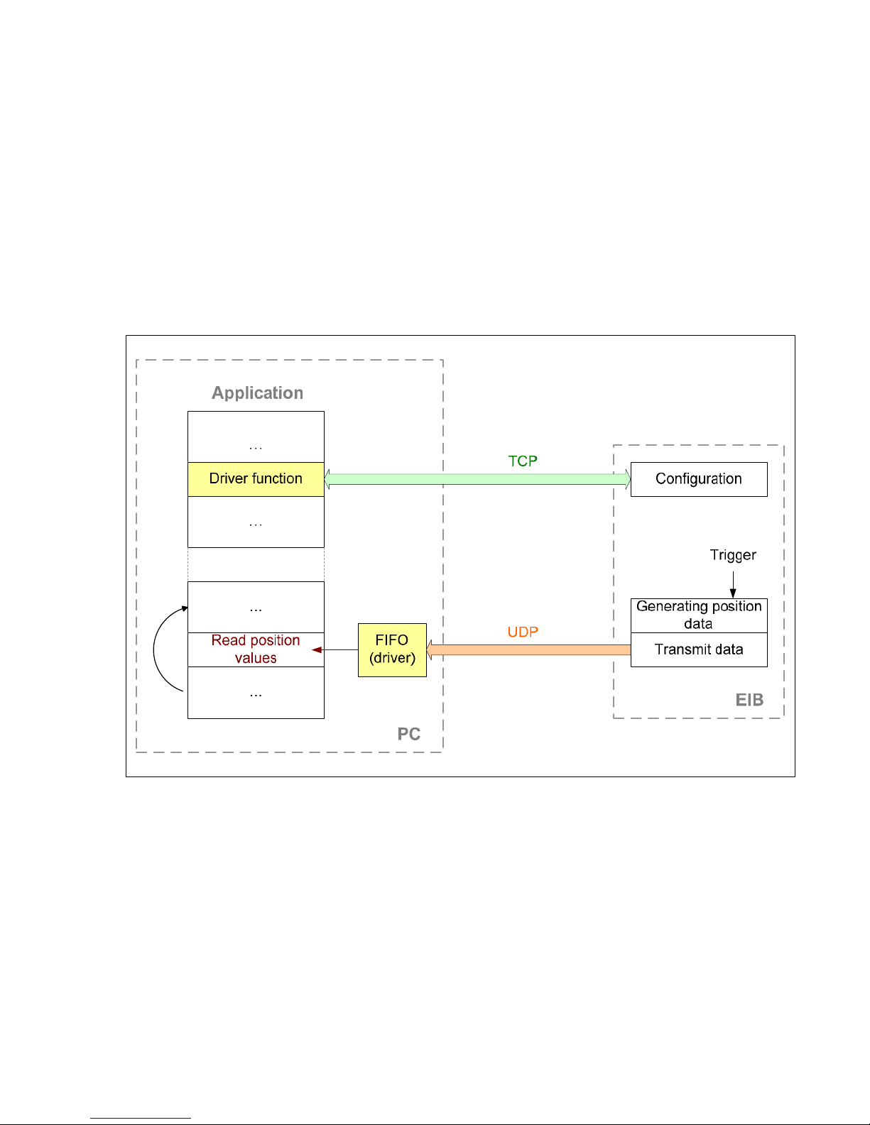
7.3 "Soft Real-Time" Operating Mode
The position data is transported with UDP packets from the EIB 74x to the PC. This occurs parallel to the TCP
communication via the standard Ethernet interface. The position data is generated when the EIB 74x receives a trigger
signal. With each trigger event, a data packet is sent to the PC automatically. Here, the packets can be read from a FIFO.
For operation in Soft Real-Time mode, the EIB 74x must be configured following the steps listed below.
• Initialization of the EIB 74x
• Initialization and configuration of the axes
• Configuration of the data packet
• Configuration of the trigger logic
• Selection of the operating mode (Soft Real-Time)
• Activation of the trigger source
The diagram below illustrates the communication process schematically. The customer software application has to configure
the EIB 74x. The data is then transmitted to the FIFO independently. From here, the application can read out the data within
a program loop.
Parallel to the position poll, the status of the EIB 74x can be requested or error messages cleared.
If the Ethernet connection is terminated in Soft Real-Time mode, e.g. by unplugging the Ethernet cable, the EIB 74x
deactivates the trigger source and transmits no further UDP packets. Once the connection has been restored, the EIB 74x
must be reconfigured for the operating mode.
When the application is closed, the above-mentioned initialization steps must be taken in the reverse order. The trigger
source must be deactivated first. The operating mode can then be changed or the connection to the EIB 74x closed.
Processing trigger events:
• External trigger inputs are supported
• Internal trigger sources are supported
• Software triggers are supported
For correct interpretation of the data, the composition of the data packet must be considered during data evaluation.
26
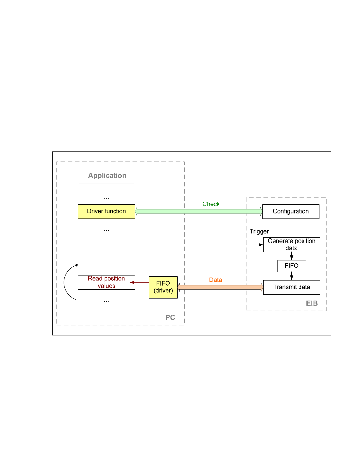
7.4 "Streaming" Operating Mode
The position data are buffered by the EIB 74x and transported to the PC. This occurs parallel to the TCP communication via
the standard Ethernet interface. The position data is generated when the EIB 74x receives a trigger signal. A data packet is
generated with each trigger event. Depending on the trigger rate and data volume, multiple data packets are consolidated
and transmitted to the PC. Here, the packets can be read from a FIFO.
For operation in Streaming mode, the EIB 74x must be configured following the steps listed below.
• Initialization of the EIB 74x
• Initialization and configuration of the axes
• Configuration of the data packet
• Configuration of the trigger logic
• Selection of the operating mode (Streaming)
• Activation of the trigger source
The diagram below illustrates the communication process schematically. The customer software application has to configure
the EIB 74x. The data is then transmitted to the FIFO independently. From here, the application can read out the data within
a program loop.
Parallel to the position poll, the status of the EIB 74x can be requested or error messages cleared. In particular, the status of
the FIFO in the EIB 74x can be interrogated in order to detect overflow early.
As soon as the position values from the FIFO are read on the PC, this is confirmed to the EIB. If further data are available in
the EIB 74x, they are transmitted.
When the application is closed, the above-mentioned initialization steps must be taken in the reverse order. The trigger
source must be deactivated first. The operating mode can then be changed or the connection to the EIB 74x closed.
Processing trigger events:
• External trigger inputs are supported
• Internal trigger sources are supported
• Software triggers are supported
For correct interpretation of the data, the composition of the data packet must be considered during data evaluation.

27
7.5 "Recording" Operating Mode
The position data is saved in the memory of the EIB 74x. A data packet is generated and saved with each trigger event. After
the recording phase ends, the data can be transmitted.
The Recording operating mode supports two further modes. In Single Shot mode, data recording is automatically ended as
soon as the memory is full. In the Rolling mode the data is saved in a ring buffer. When the memory is full, the oldest entry
is overwritten. After the Recording mode is ended, the last n samples can be read from the memory.
The recording depth depends on the size of the data packet and can be read out (see Part 2, 7.42).
For operation in Recording mode, the EIB 74x must be configured following the steps listed below.
• Initialization of the EIB 74x
• Initialization and configuration of the axes
• Configuration of the data packet
• Configuration of the trigger logic
• Selection of the operating mode (Recording)
• Activation of the trigger source
After the recording phase is concluded, the following steps have to be taken:
• Deactivation of the trigger source
• Selection of the operating mode (Polling)
• Starting data transmission
The diagram below illustrates the communication process schematically. The customer software application has to configure
the EIB 74x. In the first phase (recording) the data is saved in the EIB 74x. In the second phase (data transmission) the data
is transmitted to the host and saved in a FIFO. From here, the application can read out the data within a program loop.
During the recording, the status of the EIB 74x can be requested or error messages cleared. In particular, the status of the
memory in the EIB 74x can be interrogated.
Processing trigger events:
• External trigger inputs are supported
• Internal trigger sources are supported
• Software triggers are supported
For correct interpretation of the data, the composition of the data packet must be considered during data evaluation.
 Loading...