

Page 1
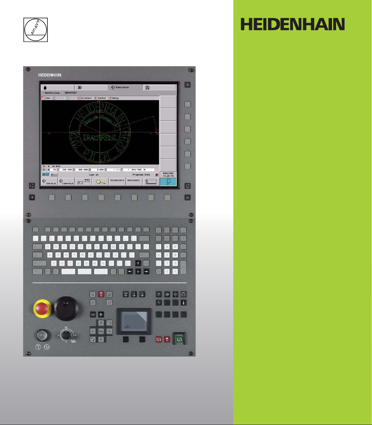
Operating Instructions
DataPilot 4290 V7
Engraving Inscriptions
English (en)
8/2005
Page 2

1 Engraving .................................................................................................... 1
1.1 Engraving inscriptions ........................................................................ 1
1.2 Parameters of the Subprogram Call ................................................... 3
1.3 Example: Engraving the Front Face .................................................... 4
1.4 Example: Engraving the Lateral Surface ............................................. 8
1.5 Character Set .................................................................................... 10
Page 3
1 Engraving
HEIDENHAIN includes a set of NC subprograms with
DataPilot for engraving inscriptions (large and small
letters, numbers, and various special characters).
The installation program transfers these NC
subprograms together with the NC sample programs
Grav_Sti and Grav_Man into the machine “BEISPIEL.”
The names of the NC subprograms are listed in the
Engraving Inscriptions operating instructions.
The subprograms and sample programs for engraving
are also saved in compressed format in the file
Grav_4290.zip in the machine “BEISPIEL” in the
“NCPS” directory. Copy this ZIP file to the NCPS
directory of other DataPilot machines and unzip it if
you want to engrave with other DataPilot machines as
well.
The compressed file with subprograms and sample
programs for engraving is also on the DataPilot CDROM (path: JH\DP4290\ZIP\Grav_4290.zip).
1.1 Engraving inscriptions
The C or Y axis is used for engraving. You can adjust
the size, orientation and position of the characters.
As a default, the subprograms engrave the character
strings
on the front face: linear or polar
on the lateral surface: linear
The momentarily valid machining plane determines
whether the C or Y axis is used for engraving:
G17 (XY): Y axis
G18 (ZX): C axis
G19 (ZY): Y axis
August 2005 Engraving 1
Page 4
Engraving characters strings
Program a character string according to the following scheme (in the
BEARBEITUNG section):
8 Insert a milling tool
8 Pre-position the milling tool to the beginning of the character
string
8 Call in sequence the subprograms with the characters to be
engraved
8 Retract the tool
The characters are engraved starting at the current tool
position. The reference point depends on whether the
characters are in linear or polar alignment:
Linear: The reference point is the bottom left corner of
the character
Polar: The reference point is the center of the bottom
edge of the character
2 HEIDENHAIN DataPilot 4290 V7
Page 5

1.2 Parameters of the Subprogram Call
Specify in the call parameters of the subprogram the details of the
characters’ appearance.
8 Program name L: Name of the subprogram (See “Character Set” on
page 45.)
8 extern=1 V: Enter “1” for an external subprogram
8 Font height LA: Letter height in [mm]
8 Angle LB: Rotated angle of the letter in [°]
Linear front face: 0° = Vertical characters: the characters are
aligned in sequence in positive XK direction
Polar front face: LB has no function
Lateral surface 0°: Characters are engraved from –CY to +CY
Lateral surface 90°: Characters are engraved from –Z to +Z
8 Milling plane LC:
Front face: Z position, infeed depth during milling
Lateral surface: X diameter, infeed depth during milling
8 Retraction plane LD:
Front face: Z position retracted to for positioning
Lateral surface: X diameter retracted to for positioning
8 0=Front/1=Lateral LE: Engraving on the front face or lateral
surface
0: Front face
1: Lateral surface
8 0=lin 1/2=polar LF: Only relevant for the front face
0: Characters are aligned linearly
1: Characters are bent upwards over the center of the coordinate
cross
2: Characters are bent downwards under the center of the
coordinate cross
8 Reference diameter LH:
Front face: Diameter over which the character string is engraved
with polar alignment
Lateral surface: Diameter for calculation of the unrolled lateral
surface (G120)
8 Separation factor I: The separation between the characters is
calculated according to the following formula: LA / 6 * I
If I is not entered, I=1 is used for calculation.
8 Number of repetitions Q: can be used if the same character is to
be engraved immediately following
August 2005 Engraving 3
Page 6

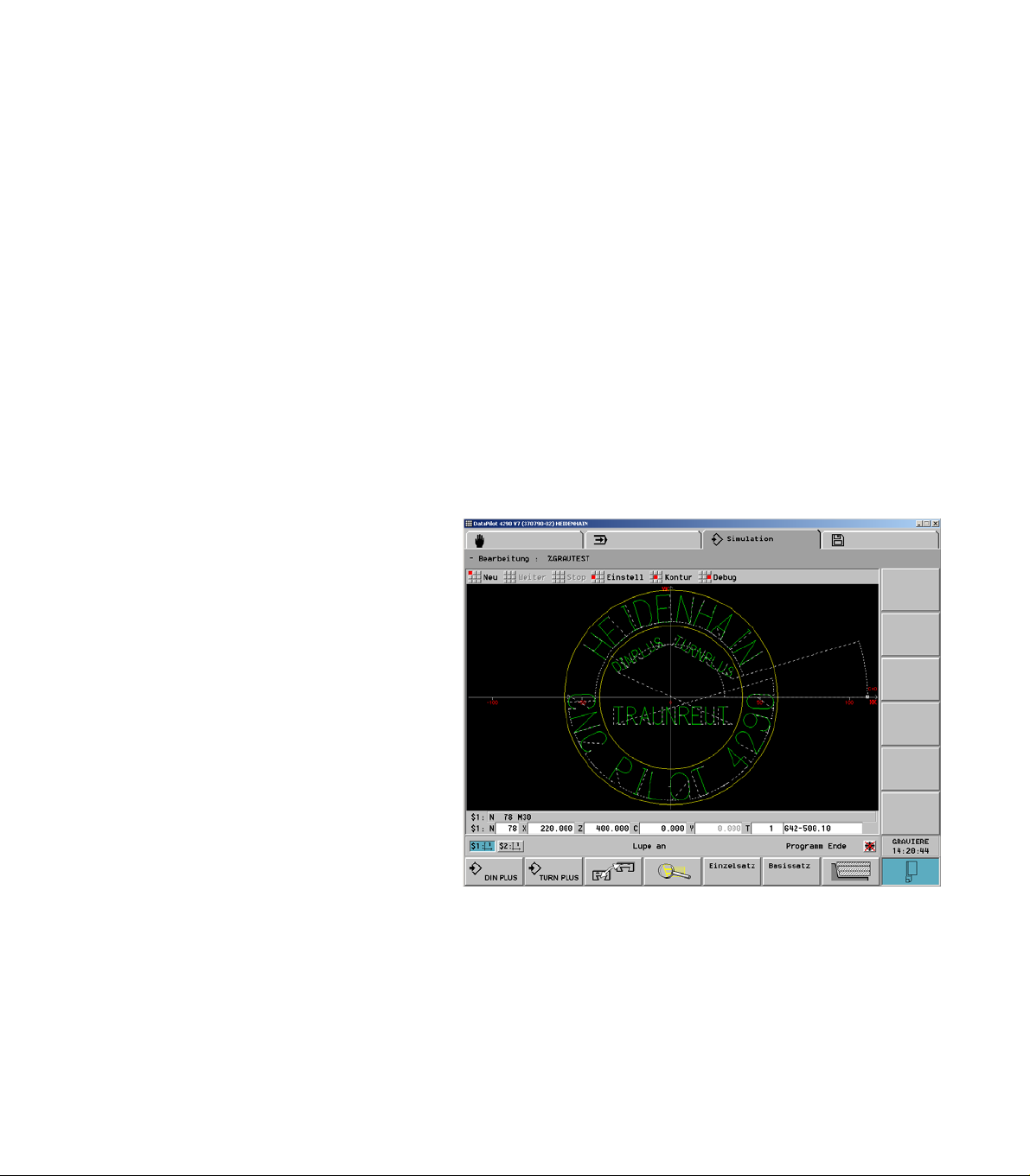
1.3 Example: Engraving the Front Face
The following example engraves character strings in
various orientations and positions onto the front face.
Character string “HEIDENHAIN”
The character string is engraved in polar alignment,
bent upwards, at Z = – 10.
Programming the character string:
8 Position the tool to C=145°
8 Parameters for subprogram call:
Letter height: LA=15 mm
Milling plane at Z=–10 (LC=–10)
Retraction plane at Z=–7 (LD=–7)
Engraving on the front face (LE=0)
Polar character string bent upwards (LF=1)
Diameter over which the character string is
engraved (LH): Bottom edge of character=85
Separation factor (I) is not programmed; the
default separation is valid
Example: Program and block structure
. . .
N16 G110 C0
N17 G100 XK30 YK0
N18
N19 G110 C145
N20 L"H" V1 LA15 LC-10 LD-7 LE0 LF1 LH85
N21 L"E" V1 LA15 LC-10 LD-7 LE0 LF1 LH85
N22 L"I" V1 LA15 LC-10 LD-7 LE0 LF1 LH85
N23 L"D" V1 LA15 LC-10 LD-7 LE0 LF1 LH85
N24 L"E" V1 LA15 LC-10 LD-7 LE0 LF1 LH85
N25 L"N" V1 LA15 LC-10 LD-7 LE0 LF1 LH85
N26 L"H" V1 LA15 LC-10 LD-7 LE0 LF1 LH85
N27 L"A" V1 LA15 LC-10 LD-7 LE0 LF1 LH85
N28 L"I" V1 LA15 LC-10 LD-7 LE0 LF1 LH85
N29 L"N" V1 LA15 LC-10 LD-7 LE0 LF1 LH85
N.. . . .
4 HEIDENHAIN DataPilot 4290 V7
Page 7

Character string “CNC PILOT 4290”
The character string is engraved in polar alignment,
bent downwards, at Z = – 10.
Programming the character string:
8 Position the tool to C=182.5°
8 Parameters for subprogram call:
Letter height: LA=15 mm
Milling plane at Z=–10 (LC=–10)
Retraction plane at Z=–7 (LD=–7)
Engraving on the front face (LE=0)
Polar character string bent downwards (LF=2)
Diameter over which the character string is
engraved (LH): Bottom edge of character=115
Separation factor: 1.3 * default separation (I=1.3)
Example: Program and block structure
. . .
N30 G110 C182.5
N32 L"C" V1 LA15 LC-10 LD-7 LE0 LF2 LH115 I1.3
N33 L"N" V1 LA15 LC-10 LD-7 LE0 LF2 LH115 I1.3
N34 L"C" V1 LA15 LC-10 LD-7 LE0 LF2 LH115 I1.3
N35 L"BLANK" V1 LA15 LC-10 LD-7 LE0 LF2 LH115 I1.3
N36 L"P" V1 LA15 LC-10 LD-7 LE0 LF2 LH115 I1.3
N37 L"I" V1 LA15 LC-10 LD-7 LE0 LF2 LH115 I1.3
N38 L"L" V1 LA15 LC-10 LD-7 LE0 LF2 LH115 I1.3
N39 L"O" V1 LA15 LC-10 LD-7 LE0 LF2 LH115 I1.3
N40 L"T" V1 LA15 LC-10 LD-7 LE0 LF2 LH115 I1.3
N41 L"BLANK" V1 LA15 LC-10 LD-7 LE0 LF2 LH115 I1.3
N42 L"4" V1 LA15 LC-10 LD-7 LE0 LF2 LH115 I1.3
N43 L"2" V1 LA15 LC-10 LD-7 LE0 LF2 LH115 I1.3
N44 L"9" V1 LA15 LC-10 LD-7 LE0 LF2 LH115 I1.3
N45 L"0" V1 LA15 LC-10 LD-7 LE0 LF2 LH115 I1.3
N.. . . .
August 2005 Engraving 5
Page 8

Character string “Traunreut”
The character string is engraved linearly.
Programming the character string:
8 Position the tool to XK = –32, YK = –15
8 Parameters for subprogram call:
Letter height: LA=10 mm
Angle (LB) is not programmed; the default of 0° is
valid
Milling depth to Z=0 (LC=0)
Retraction plane to Z=3 (LD=3)
Engraving on the front face (LE=0)
Linear character string (LF=0)
Separation factor: 1.4 * default separation (I=1.4)
Example: Program and block structure
. . .
N47 G100 XK-32 YK-15
N48 L"T" V1 LA10 LC0 LD3 LE0 LF0 I1.4
N49 L"R" V1 LA10 LC0 LD3 LE0 LF0 I1.4
N50 L"A" V1 LA10 LC0 LD3 LE0 LF0 I1.4
N51 L"U" V1 LA10 LC0 LD3 LE0 LF0 I1.4
N52 L"N" V1 LA10 LC0 LD3 LE0 LF0 I1.4
N53 L"R" V1 LA10 LC0 LD3 LE0 LF0 I1.4
N54 L"E" V1 LA10 LC0 LD3 LE0 LF0 I1.4
N55 L"U" V1 LA10 LC0 LD3 LE0 LF0 I1.4
N56 L"T" V1 LA10 LC0 LD3 LE0 LF0 I1.4
N.. . . .
6 HEIDENHAIN DataPilot 4290 V7
Page 9

Character string “DIN PLUS, TURN
PLUS”
The character string “DIN PLUS” is engraved linearly
at an angle of +30°, and “TURN PLUS” at –30°.
Programming the character string:
8 Position the tool to XK = –33, YK = –10
8 Parameters for subprogram call:
Letter height (LA): 6 mm for “DIN PLUS”, 5 mm
for “TURN PLUS”
Angle (LB): 30° for “DIN PLUS”, –30° for “TURN
PLUS”
Milling depth to Z=0 (LC=0)
Retraction plane to Z=3 (LD=3)
Engraving on the front face (LE=0)
Linear character string (LF=0)
Separation factor: 1.8 * default separation (I=1.8)
Example: Program and block structure
. . .
N58 G100 XK-33 YK10
N59 L"D" V1 LA6 LB30 LC0 LD3 LE0 LF0 I1.8
N60 L"I" V1 LA6 LB30 LC0 LD3 LE0 LF0 I1.8
N61 L"N" V1 LA6 LB30 LC0 LD3 LE0 LF0 I1.8
N62 L"BLANK" V1 LA6 LB30 LC0 LD3 LE0 LF0 I1.8
N63 L"P" V1 LA6 LB30 LC0 LD3 LE0 LF0 I1.8
N64 L"L" V1 LA6 LB30 LC0 LD3 LE0 LF0 I1.8
N65 L"U" V1 LA6 LB30 LC0 LD3 LE0 LF0 I1.8
N66 L"S" V1 LA6 LB30 LC0 LD3 LE0 LF0 I1.8
N67 G100 X55 C90
N68 L"T" V1 LA5 LB-30 LC0 LD3 LE0 LF0 I1.8
N69 L"U" V1 LA5 LB-30 LC0 LD3 LE0 LF0 I1.8
N70 L"R" V1 LA5 LB-30 LC0 LD3 LE0 LF0 I1.8
N71 L"N" V1 LA5 LB-30 LC0 LD3 LE0 LF0 I1.8
N72 L"P" V1 LA5 LB-30 LC0 LD3 LE0 LF0 I1.8
N73 L"L" V1 LA5 LB-30 LC0 LD3 LE0 LF0 I1.8
N74 L"U" V1 LA5 LB-30 LC0 LD3 LE0 LF0 I1.8
N75 L"S" V1 LA5 LB-30 LC0 LD3 LE0 LF0 I1.8
N.. . . .
August 2005 Engraving 7
Page 10

1.4 Example: Engraving the Lateral Surface
Character string “Steuerungen”
The character string “Steuerungen” (“Controls”) is
engraved from –CY to +CY.
Programming the character string:
8 Position the tool to Z=–150 and C=–45°
8 Parameters for subprogram call:
Letter height: LA=12 mm
Angle: LB=0° (from –CY to +CY)
Milling depth to diameter 120 (LC=120)
Retraction depth to diameter 126 (LC=126)
Engraving on the lateral surface (LE=1)
Linear character string (LF=0)
Diameter (for G120): LH=120
Separation factor: 1.3 * default separation (I=1.3)
Example: Program and block structure
. . .
N17 G0 X126
N18 G0 Z-150
N19 G110 C-45
N20 L"S" V1 LA12 LB0 LC120 LD126 LE1 LF0 LH120 I1.3
N21 L"KT" V1 LA12 LB0 LC120 LD126 LE1 LF0 LH120 I1.3
N22 L"KE" V1 LA12 LB0 LC120 LD126 LE1 LF0 LH120 I1.3
N23 L"KU" V1 LA12 LB0 LC120 LD126 LE1 LF0 LH120 I1.3
N24 L"KE" V1 LA12 LB0 LC120 LD126 LE1 LF0 LH120 I1.3
N25 L"KR" V1 LA12 LB0 LC120 LD126 LE1 LF0 LH120 I1.3
N26 L"KU" V1 LA12 LB0 LC120 LD126 LE1 LF0 LH120 I1.3
N27 L"KN" V1 LA12 LB0 LC120 LD126 LE1 LF0 LH120 I1.3
N28 L"KG" V1 LA12 LB0 LC120 LD126 LE1 LF0 LH120 I1.3
N29 L"KE" V1 LA12 LB0 LC120 LD126 LE1 LF0 LH120 I1.3
N30 L"KN" V1 LA12 LB0 LC120 LD126 LE1 LF0 LH120 I1.3
N31 L"BLANK" V1 LA12 LB0 LC120 LD126 LE1 LF0 LH120 I1.3
N.. . . .
8 HEIDENHAIN DataPilot 4290 V7
Page 11

Character string “der Extra-Klasse”
The character string “der Extra-Klasse” (“in a class of
their own”) is engraved from –Z to +Z.
Programming the character string:
8 Position the tool to Z=–150 and C=45°
8 Parameters for subprogram call:
Letter height: LA=12 mm
Angle: LB=90° (from –Z to +Z)
Milling depth to diameter 120 (LC=120)
Retraction depth to diameter 126 (LC=126)
Engraving on the lateral surface (LE=1)
Linear character string (LF=0)
Diameter (for G120): LH=120
Separation factor (I) is not programmed; the
default separation is valid
Example: Program and block structure
. . .
N36 G0 Z-150
N37 G110 C45
N38 L"KD" V1 LA12 LB90 LC120 LD126 LE1 LF0 LH120
N39 L"KE" V1 LA12 LB90 LC120 LD126 LE1 LF0 LH120
N40 L"KR" V1 LA12 LB90 LC120 LD126 LE1 LF0 LH120
N41 L"BLANK" V1 LA12 LB90 LC120 LD126 LE1 LF0 LH120
N42 L"E" V1 LA12 LB90 LC120 LD126 LE1 LF0 LH120
N43 L"KX" V1 LA12 LB90 LC120 LD126 LE1 LF0 LH120
N44 L"KT" V1 LA12 LB90 LC120 LD126 LE1 LF0 LH120
N45 L"KR" V1 LA12 LB90 LC120 LD126 LE1 LF0 LH120
N46 L"KA" V1 LA12 LB90 LC120 LD126 LE1 LF0 LH120
N47 L"MINUS" V1 LA12 LB90 LC120 LD126 LE1 LF0 LH120
N48 L"KL" V1 LA12 LB90 LC120 LD126 LE1 LF0 LH120
N49 L"KA" V1 LA12 LB90 LC120 LD126 LE1 LF0 LH120
N50 L"KS" V1 LA12 LB90 LC120 LD126 LE1 LF0 LH120
N51 L"KS" V1 LA12 LB90 LC120 LD126 LE1 LF0 LH120
N52 L"KE" V1 LA12 LB90 LC120 LD126 LE1 LF0 LH120
N53 L"BLANK" V1 LA12 LB90 LC120 LD126 LE1 LF0 LH120
N.. . . .
August 2005 Engraving 9
Page 12

1.5 Character Set
Charact
ers
Small letters Capital letters Numbers
. . . KOE . . . OE . . .
Special characters
SP call
KA KAE A AE 0
KZ KUE Z UE 9
SZ
AT EKZU GRAD MINUS RKAUF
BLANK EURO GROESSE
Charact
ers
SP call
Charact
ers
SP call
R
Charact
ers
SP call
MUE RKZU
Charact
ers
SP call
DPUNKT GKAUF KLEINER PLUS USTRICH
DURCH GKZU KOMMA PROZENT
EKAUF GLEICH MAL PUNKT
10 HEIDENHAIN DataPilot 4290 V7
 Loading...