

Page 1
CNC PILOT 4290
NC Software
368 650-xx
V7
User’s Manual
English (en)
10/2004
Page 2
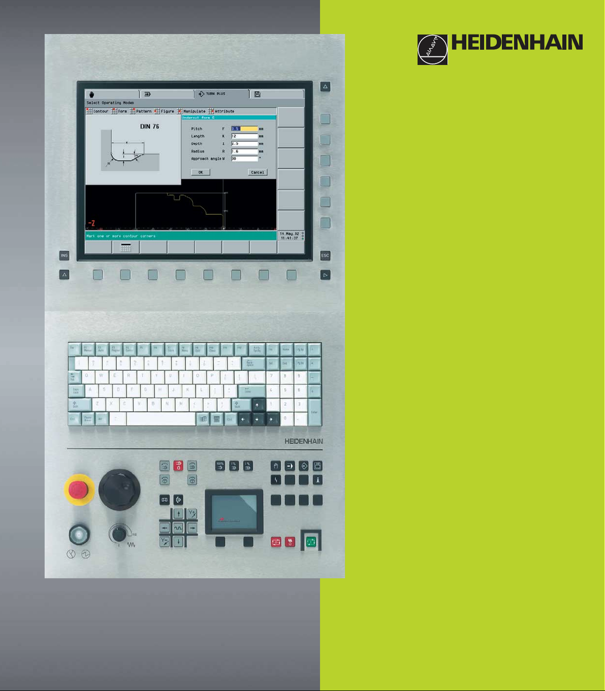
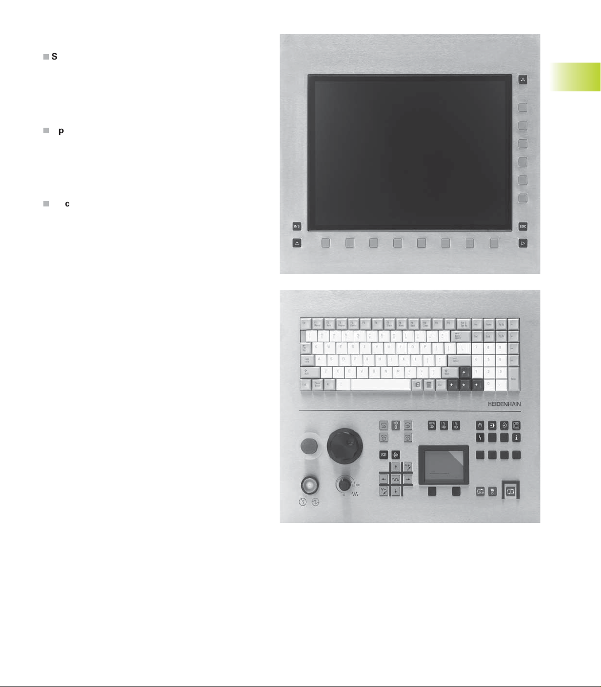
Data input keypad
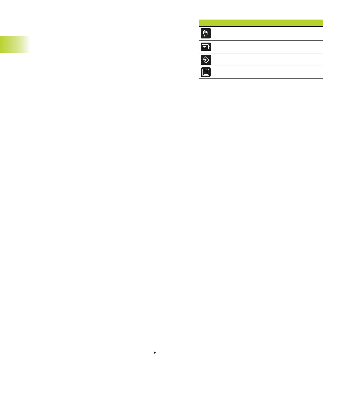
Manual operating mode
Machine operating panel
Cycle Start
Automatic mode
Programming modes (DIN PLUS, simulation, TURN
PLUS)
Organization modes (parameter, service, transfer)
Display error status
Call the info system
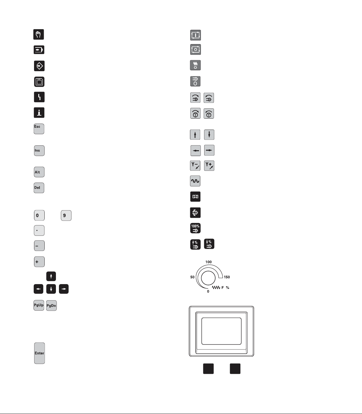
ESC (escape)
■ Go back by one menu level
■ Close dialog box, do not save
INS (insert)
■ Insert list element
■ Close dialog box, save data
ALT (alter)
■ Change the list element
DEL (delete)
■ Deletes the list element
■ deletes the selected character or the character to
the left of the cursor.
. . . Numbers for value input and soft-key
selection
Decimal point
Cycle Stop
Feed Stop
Spindle Stop
Spindle on – M3/M4 direction
Spindle jog – M3/M4 direction (The
spindle turns until you press the key.
Manual direction keys +X/–X
Manual direction keys +Z/–Z
Manual direction keys +Y/–Y
Rapid traverse key
Slide change key
Spindle change key
Spindle speed at the programmed value
Minus as algebraic sign
”Continue key” for special functions (e.g. marking)
Arrow keys
Page forward, page backward
■ Change to previous/next screen page
■ Change to previous/next dialog box
■ Switch between input windows
Enter – Confirmation of input
Increase/decrease spindle speed by 5%
Override dial for feed rate
Touch pad with right and left
mouse key
Page 3

Page 4

CNC PILOT 4290, Software and
Functions
This manual describes functions that are available in the CNC PILOT
4290 with NC software number 368 650-xx (Release 7.0). For
programming the Y-axis, please refer to the User's Manual ”CNC
PILOT 4290 with Y-Axis”. It is not described in this manual.
The machine manufacturer adapts the features offered by the control
to the capabilities of the specific lathe by setting machine parameters.
Therefore, some of the functions described in this manual may not be
among the features provided by the CNC PILOT on your machine tool.
Some of the CNC PILOT functions which are not available on every
machine are:
■ Machining with the C axis
■ Machining with the Y-axis
■ Full-surface machining
■ Tool monitoring
■ Graphically supported interactive contour definition
■ Automatic or graphically supported interactive DIN PLUS program
generation
Please contact your machine manufacturer for detailed information on
the features that are supported by your machine tool.
Many machine manufacturers and HEIDENHAIN offer programming
courses for the CNC PILOT controls. We recommend these courses
as an effective way of improving your programming skills and sharing
information and ideas with other CNC PILOT users.
HEIDENHAIN also offers the PC software DataPilot 4290, which is
designed for use with the CNC PILOT 4290. The DataPilot is suitable
for both shop-floor programming as well as off-location program
creation and testing. It is also ideal for training purposes. DataPilot
can be run on WINDOWS 95, WINDOWS 98, WINDOWS ME,
WINDOWS NT 4.0 or WINDOWS 2000.
Intended place of operation
The CNC PILOT 4290 complies with EN 55022, Class A, and is
intended primarily for operation in industrially zoned areas.
Page 5
Contents
Introduction and Fundamentals
1
Basics of operation
Manual Control and Automatic Modes
DIN PLUS
Graphic Simulation
TURN PLUS
Parameter
Operating Resources
Service and Diagnosis
Transfer
Tables and overviews
2
3
4
5
6
7
8
9
10
11
Contents
HEIDENHAIN CNC PILOT 4290
I
Page 6

1 Introduction and Fundamentals..... 1
1.1 The CNC PILOT..... 2
1.2 The Operating Modes..... 5
Contents
1.3 Expansion Stages (Options)..... 6
1.4 Fundamentals..... 7
1.5 Tool Dimensions..... 10
2 Basics of Operation..... 11
2.1 User Interface..... 12
2.1.1 Screen Displays..... 12
2.1.2 Controls and Displays..... 13
2.1.3 Selection of Operating Modes..... 14
2.1.4 Selection of Functions, Data Input..... 14
2.2 The Info System..... 16
2.3 The Error System..... 17
2.3.1 Direct Error Messages..... 17
2.3.2 Error Display, PLC Display..... 17
2.4 Data Backup..... 19
2.5 Explanation of Terms..... 19
3 Manual Control and Automatic mode..... 21
3.1 Switch-On, Switch-Off, Reference Run..... 22
3.1.1 Switch-On and Traversing the Reference Marks..... 22
3.1.2 Switch-Off..... 23
3.2 Manual Operating Mode..... 24
3.2.1 Entering machine data..... 25
3.2.2 M Commands..... 25
3.2.3 Manual Turning Operations..... 26
3.2.4 Handwheel..... 26
3.2.5 Spindle and Axis Direction Keys..... 27
3.2.6 Slide/Spindle change key..... 27
3.3 Tool Lists, Tool Life Management..... 28
3.3.1 Setting Up a Tool List..... 29
3.3.2 Comparing a Tool List with an NC Program..... 31
3.3.3 Transferring the Tool List from an NC Program..... 32
3.3.4 Tool Life Management..... 33
3.4 Setup Functions..... 34
3.4.1 Defining the Tool Change Position..... 34
3.4.2 Shifting the Workpiece Datum..... 35
3.4.3 Defining the protection zone..... 36
3.4.4 Setting up the Chucking Table..... 37
3.4.5 Setting up Machine Dimensions..... 38
3.4.6 Measuring Tools..... 39
II
Contents
Page 7

3.5 Automatic Mode of Operation..... 41
3.5.1 Program Selection..... 41
3.5.2 Defining a Start Block..... 42
3.5.3 Program Sequence Modification..... 43
3.5.4 Compensation..... 44
3.5.5 Tool Life Management..... 45
3.5.6 Inspection Mode..... 46
3.5.7 Block Display..... 48
3.5.8 Graphic Display..... 49
3.5.9 Post-Process Measuring Status Display..... 51
3.6 Machine Display..... 52
3.7 Load Monitoring..... 54
3.7.1 Reference Machining..... 54
3.7.2 Production Using Load Monitoring..... 55
3.7.3 Editing Limit Values..... 56
3.7.4 Analyzing Reference Machining..... 57
3.7.5 Machining Using Load Monitoring..... 57
3.7.6 Load Monitoring Parameters..... 58
4 DIN PLUS..... 59
4.1 DIN Programming..... 60
4.1.1 Introduction..... 60
4.1.2 DIN PLUS Screen..... 61
4.1.3 Linear and Rotary Axes..... 62
4.1.4 Units of Measurement..... 63
4.1.5 Elements of the DIN Program..... 63
4.2 Programming Notes..... 65
4.2.1 Parallel Editing..... 65
4.2.2 Address Parameters..... 65
4.2.3 Contour Programming..... 66
4.2.4 Tool Programming..... 68
4.2.5 Fixed cycles..... 69
4.2.6 NC Subprograms..... 70
4.2.7 Template Control..... 70
4.2.8 NC Program Interpretation..... 70
4.3 The DIN PLUS Editor..... 71
4.3.1 Main Menu..... 72
4.3.2 Geometry Menu..... 75
4.3.3 Machining Menu..... 76
4.3.4 Block Menu..... 77
Contents
HEIDENHAIN CNC PILOT 4290
III
Page 8

4.4 Program Section Codes..... 79
Contents
4.5 Geometry Commands..... 84
4.6 Machining Commands..... 110
4.7 Turning Cycles..... 122
4.8 Thread Cycles..... 140
4.9 Drilling cycles..... 143
4.10 C-Axis Machining..... 148
4.11 Milling Cycle Group..... 152
4.12 Special functions..... 159
4.4.1 PROGRAMMKOPF [PROGRAM HEAD]..... 79
4.4.2 TURRET..... 80
4.4.3 CHUCKING EQUIPMENT..... 82
4.4.4 Contour Definition..... 82
4.4.5 BEARBEITUNG [MACHINING]..... 83
4.4.6 UNTERPROGRAMM [SUBPROGRAM]..... 83
4.5.1 Definition of Blank..... 84
4.5.2 Basic Contour Elements..... 84
4.5.3 Contour Form Elements..... 86
4.5.4 Help Commands for Contour Definition..... 92
4.5.5 Contour Position..... 95
4.5.6 Front and Rear Face Contours..... 96
4.5.7 Lateral Surface Contours..... 102
4.5.8 Circular Pattern with Circular Slots..... 108
4.6.1 Assigning the Contour to the Operation..... 110
4.6.2 Tool Positioning without Machining..... 110
4.6.3 Simple Linear and Circular Movements..... 111
4.6.4 Feed Rate and Spindle Speed..... 113
4.6.5 Cutter Radius Compensation (TRC/MCRC)..... 115
4.6.6 Zero Point Shift..... 116
4.6.7 Oversizes, Safety Clearances..... 118
4.6.8 Tools, Types of Compensation..... 120
4.7.1 Contour-Based Turning Cycles..... 122
4.7.2 Simple Turning Cycles..... 134
4.10.1 General C-Axis Functions..... 148
4.10.2 Front/Rear Face Machining..... 149
4.10.3 Lateral Surface Machining..... 150
4.12.1 Chucking Equipment in Simulation..... 159
4.12.2 Slide Synchronization..... 160
4.12.3 Spindle Synchronization, Workpiece Transfer..... 161
4.12.4 Contour Follow-Up..... 164
4.12.5 In-Process Measuring..... 165
IV
Contents
Page 9

4.12.6 Post-Process Measuring..... 166
4.12.7 Load Monitoring..... 167
4.13 Other G Functions..... 168
4.14 Data Input and Data Output..... 173
4.14.1 Input/Output of # Variables..... 173
4.14.2 Input/Output of V Variables..... 174
4.15 Programming Variables..... 175
4.15.1 # Variables..... 175
4.15.2 V Variables..... 177
4.15.3 Program Branches, Program Repeats, Conditional Block Execution..... 179
4.16 Subprograms..... 182
4.17 M Functions..... 183
4.18 Programming Notes and Examples..... 184
4.18.1 Programming Machining Cycles..... 184
4.18.2 Contour Repetitions..... 184
4.18.3 Full-Surface Machining..... 187
5 Graphic Simulation..... 195
5.1 Simulation Mode of Operation..... 196
5.1.1 Graphic Elements, Displays..... 197
5.1.2 Basics of Operation..... 200
5.2 Main Menu..... 201
5.3 Contour Simulation..... 203
5.3.1 Contour-Simulation Functions..... 203
5.3.2 Dimensioning..... 204
5.4 Machining Simulation..... 205
5.5 Motion Simulation..... 207
5.6 Zoom Function..... 208
5.7 3-D View..... 209
5.8 Checking the
5.9 Time Calculation..... 212
5.10 Synchronous Point Analysis..... 213
6 TURN PLUS..... 215
6.1 TURN PLUS Mode of Operation..... 216
6.2 Program Management..... 217
6.2.1 TURN PLUS Files..... 217
6.2.2 Program Head..... 218
6.3 Workpiece Description..... 219
6.3.1 Entering the Contour of a Blank Part..... 219
6.3.2 Input of the Finished Part Contour..... 220
6.3.3 Superimposing form elements..... 221
6.3.4 Integrating a Contour Train..... 222
Contents
HEIDENHAIN CNC PILOT 4290
V
Page 10

Contents
6.4 Contours of Workpiece Blanks..... 228
6.5 Contour of Finished Part..... 229
6.6 C-Axis Contours..... 242
6.7 Manipulating Contours..... 256
6.8 Importing DXF Contours..... 263
6.9 Assigning attributes..... 267
6.10 User Aids..... 273
6.11 Preparing a Machining Process..... 277
6.3.5 Entering Contours Machined with the C Axis..... 223
6.3.6 Basics of Operation..... 225
6.3.7 Help Functions for Element Definition..... 226
6.5.1 Basic Contour Elements..... 229
6.5.2 Form elements..... 232
6.5.3 Overlay Elements..... 239
6.6.1 Contours on the Front and Rear Face..... 242
6.6.2 Contours of the Lateral Surface..... 249
6.7.1 Editing the Contours of a Blank Part..... 256
6.7.2 Trimming..... 256
6.7.3 Change..... 258
6.7.4 Deleting..... 259
6.7.5 Inserting..... 260
6.7.6 Transformations..... 261
6.7.7 Connect..... 262
6.7.8 Resolve..... 262
6.8.1 Fundamentals..... 263
6.8.2 Configuring the DXF Import..... 264
6.8.3 DXF-Import..... 266
6.8.4 Transferring and Organizing DXF Files..... 266
6.9.1 Attributes for Workpiece Blanks..... 267
6.9.2 Oversize..... 267
6.9.3 Feed rate/peak-to-valley height..... 267
6.9.4 Precision stop..... 268
6.9.5 Separation Points..... 268
6.9.6 Machining Attributes..... 269
6.10.1 Calculator..... 273
6.10.2 Digitizing..... 274
6.10.3 Inspector – Checking Contour Elements..... 274
6.10.4 Unresolved Contour Elements..... 275
6.10.5 Error Messages..... 276
6.11.1 Chucking a Workpiece..... 277
6.11.2 Setting Up a Tool List..... 284
VI
Contents
Page 11

6.12 Interactive Working Plan Generation (IWG)..... 286
6.12.1 Tool call..... 287
6.12.2 Cutting Data..... 288
6.12.3 Cycle specification..... 288
6.12.4 Roughing..... 289
6.12.5 Recessing..... 294
6.12.6 Drilling..... 299
6.12.7 Finishing..... 301
6.12.8 Thread Machining(G31)..... 306
6.12.9 Milling..... 307
6.12.10 Special Machining Tasks (SM)..... 309
6.13 Automatic Working Plan Generation (AWG)..... 310
6.13.1 Generating a Machining Plan..... 310
6.13.2 Machining Sequence..... 311
6.14 Control Graphics..... 321
6.15 Configuration..... 322
6.16 Machining Information..... 324
6.16.1 Tool Selection, Turret Assignment..... 324
6.16.2 Cutting Parameters..... 325
6.16.3 Coolant..... 325
6.16.4 Hollowing..... 326
6.16.5 Inside Contours..... 326
6.16.6 Drilling..... 328
6.16.7 Full-Surface Machining..... 328
6.16.9 Shaft Machining..... 330
6.17 Example..... 332
7 Parameters..... 337
7.1 Parameter Mode of Operation..... 338
7.1.1 Parameters..... 338
7.1.2 Editing Parameters..... 339
7.2 Machine Parameters..... 341
7.3 Control Parameters..... 348
7.4 Set-Up Parameters..... 355
7.5 Machining Parameters..... 357
Contents
HEIDENHAIN CNC PILOT 4290
VII
Page 12

8 Operating Resources..... 371
8.1 Tool Database..... 372
8.1.1 Tool Editor..... 372
Contents
9 Service and Diagnosis..... 401
10 Transfer..... 411
11 Tables and overviews..... 425
8.1.2 Tool Types (Overview)..... 375
8.1.3 Tool Parameters..... 377
8.1.4 Multipoint Tools, Tool Life Monitoring..... 384
8.1.5 Explanation of Tool Data..... 385
8.1.6 Tool Holder, Mounting Position..... 387
8.2 Chucking Equipment Database..... 390
8.2.1 Chucking Equipment Editor..... 390
8.2.2 Chucking Equipment Data..... 392
8.3 Technology Database (Cutting Values)..... 399
9.1 Service Mode of Operation..... 402
9.2 Service Functions..... 402
9.2.1 Access Authorization..... 402
9.2.2 System Service..... 403
9.2.3 Fixed-Word Lists..... 404
9.3 Maintenance System..... 405
9.4 Diagnosis..... 408
10.1 The Transfer Mode of Operation..... 412
10.2 Transfer Systems..... 413
10.2.1 General Information..... 413
10.2.2 Configuring for Data Transfer..... 414
10.3 Data Transfer..... 417
10.3.1 Enabling, Data Types..... 417
10.3.2 Transmitting and Receiving Files..... 418
10.4 Parameters and Operating Resources..... 420
10.4.1 Converting Parameters and Operating Resources..... 420
10.4.2 Saving Parameters and Operating Resources..... 422
10.5 File Organization..... 423
11.1 Undercut and Thread Parameters..... 426
11.1.1 Undercut DIN 76, Parameters..... 426
11.1.2 Undercut DIN 509 E, Parameters..... 427
11.1.3 Undercut DIN 509 F, Parameters..... 427
11.1.4 Thread Parameters..... 428
11.1.5 Thread Pitch..... 429
11.2 Technical Information..... 433
11.3 Peripheral Interfaces..... 437
VIII
Contents
Page 13

1
Introduction and Fundamentals
Page 14

1.1 The CNC PILOT
The CNC PILOT is a contouring control designed for
lathes and turning centers. In addition to turning
operations, you can perform milling and drilling
operations with the C-axis or the Y-axis. The CNC PILOT supports parallel machining of up to 4
workpieces in programming, testing and production.
Full-surface machining is supported on lathes with:
■ Rotating gripper
■ Movable opposing spindle
■ Multiple spindles, slides and tool carriers
1.1 The CNC PILOT
The CNC PILOT controls up to 6 slides, 4 spindles and
2 C axes.
Programming
Depending on the type and complexity of the parts to
be machined and your organization, you can choose
the type of programming best suited to your tasks.
In TURN PLUS you describe the contour of the blank
and finished part with interactive graphics. Then you
call the automatic working plan generation (AWG),
and the NC program will be generated fully
automatically at a keystroke. Alternately, you can
choose the interactive working plan generation (IWG).
When using the IWG, you determine the sequence of
machining and other technical details.
Every working step is shown in the control graphics
and can be corrected immediately. The result of program creation with TURN PLUS is a structured DIN
PLUS program.
TURN PLUS minimizes the number of entries
required, but it requires that the the tool data and
cutting data has already been entered.
If TURN PLUS fails to create the optimal NC program
for technologically sophisticated machining
operations, or if you primarily want to reduce the
machining time, program the NC program in DIN
PLUS.
DIN PLUS supports the separation of the geometric
description from the machining of the workpiece.
Powerful cycles are available for programming in DIN
PLUS. The ”simple geometry programming” function
calculates coordinates if the dimensions used in the
drawing are not suitable for NC programs.
Alternately, you can machine your workpiece in DIN
PLUS with linear and circular movements and simple
turning cycles, as you are accustomed to in
conventional DIN programming.
Both TURN PLUS and DIN PLUS support machining with the C-axis or
Y-axis and full-surface machining.
The Graphic Simulation feature enables you to subject your NC
programs to a realistic test. The CNC PILOT displays the machining of
up to 4 workpieces in the working space. Workpiece blanks and
finished parts, chucking equipment and tools are shown to scale.
You can program your NC programs and test them -even during
machining operations- directly on the machine.
Regardless of whether you are machining a simple or complex part,
producing a single part or a series of parts, or a whole batch on a
turning center, the CNC PILOT always gives you optimum support.
1 Introduction and Fundamentals2
Page 15
The C-axis
With a C-axis you can drill and mill a workpiece on its
front, back and lateral surfaces.
During use of the C-axis, one axis interpolates linearly
or circularly with the spindle in the given working plane, while the third axis interpolates linearly.
The CNC PILOT supports part program creation with
the C-axis in:
■ DIN PLUS
■ TURN PLUS contour definition
■ TURN PLUS working plan generation
TheY-axis
With a Y-axis you can drill and mill a workpiece on its
front, back and lateral surfaces.
During use of the Y-axis, two axes interpolate linearly
or circularly in the given working plane, while the third
axis interpolates linearly. This enables you to machine
slots or pockets, for example, with plane floors and
perpendicular edges. By defining the spindle angle,
you can determine the position of the milling contour
on the workpiece.
The CNC PILOT supports part program creation with
the Y-axis in:
■ DIN PLUS
■ TURN PLUS contour definition
■ TURN PLUS working plan generation
1.1 The CNC PILOT
3HEIDENHAIN CNC PILOT 4290
Page 16
Full-surface machining
The CNC PILOT supports full-surface machining for all
common machine designs. The features include anglesynchronous part transfer with rotating spindle,
traversing to a stop, controlled parting, and coordinate
transformation. This ensures efficient full-surface
machining and simple programming.
The CNC PILOT supports full surface machining in:
■ DIN PLUS
■ TURN PLUS contour definition
■ TURN PLUS working plan generation
1.1 The CNC PILOT
1 Introduction and Fundamentals4
Page 17
1.2 The Operating Modes
The functions of the CNC PILOT are grouped into the following
operating modes:
Manual operating mode
In the Manual mode you set up the machine and move the
axes manually.
Automatic mode
The NC programs are run in Automatic mode. You control and
monitor the machining of the workpiece.
DIN PLUS programming mode
In ”DIN PLUS,” you can create structured NC programs. You
first define the geometry of the blank and finished part, and
then program the individual operations.
Simulation programming mode
The Simulation mode shows a graphic representation of
programmed contours, the paths of traverse and cutting
operations.The working space, tools and chucking equipment
are shown true to scale.
During simulation, the CNC PILOT calculates the machining
and idle-machine times for every tool. For lathes with several
slides, the Synchronous point analysis enables you to
optimize your NC program.
TURN PLUS programming mode
In ”TURN PLUS” you describe the contour of the workpiece
using interactive graphics. For Automatic Working plan Generation (AWG), you select the material and chucking equipment.
The CNC PILOT will generate the NC program automatically at
a keystroke. As an alternative, you can create the working
plan with the aid of interactive graphics (IAG).
Parameter organization mode
The system behavior of the CNC PILOT is controlled with
parameters. In this mode, you set the parameters to adapt the
control to your situation.
In addition, in this mode you describe the operating resources
(tools and chucking equipment) and the cutting values.
Service organization mode
In ”Service” mode, you log on for password-protected
functions, select the conversational language and make the
system settings. This operating mode also provides diagnostic
functions for commissioning and checking the system.
Transfer organization mode
In ”Transfer” you exchange the files with other systems,
organize your programs and make data backups.
The actual control is not accessible to the machinist.
You should know, however, that your CNC PILOT has
an integrated hard disk on which all TURN PLUS and
DIN PLUS programs that you enter are stored. This
allows you to save a vast number of programs.
For data exchange and data backup, you can use the
Ethernet interface. Data exchange is also possible
over the serial interface. (RS232).
1.2 Modes of Operation
5HEIDENHAIN CNC PILOT 4290
Page 18

1.3 Expansion Stages (Options)
The machine manufacturer configures the CNC PILOT according to
the capabilities of the specific lathe. The following upgrades (options)
are available, which enable you to adapt the control to your specific
requirements:
■ TURN PLUS
Graphically supported interactive contour definition
■ Graphic description of the workpiece for blank and finished part
■ Geometry-programming function for calculating and displaying
missing contour data
■ Simple input of standard form elements like chamfers, rounding
arcs, recesses, undercuts, threads, fits, etc.
■ Easy-to-use transformations like shifting, rotating, mirroring or
multiplying
DIN PLUS program generation with interactive graphics
■ Selection of the appropriate machining method
■ Selection of the tools and definition of the cutting data
Expansion Stages (Options)
■ Direct graphic control of machining process
■ Immediate compensation possibility
Automatic DIN PLUS program generation
■ Automatic selection of tools
■ Automatic generation of working plan
■ TURN PLUS – extension by C-axis or Y-axis
■ C-axis: representation of programmed contour in the following
views: XC plane (front/rear end) and ZC plane (unrolled surface)
■ Y-axis: representation of programmed contour in the following
views: XY plane (front/rear end) YZ plane (side view)
■ Hole and figure patterns
■ Fixed cycles
■ Interactive or automatic working plan generation – also for
machining with the C-axis or Y-axis
■ TURN PLUS – extension by opposing spindle
■ Rechucking with expert program
■ Interactive or automatic generation of working plan – also for
rechucking and 2nd setup
■ In-process measuring
■ With triggering probe
■ For measuring tools
■ For measuring workpieces
■ Post-process measuring
■ Connection of measuring system via RS-232 interface
■ Evaluation of measuring results in Automatic mode
This operating manual describes all
options.The operating sequences
described in this manual may therefore
deviate from those on your machine
whenever a certain option is not supported
by your system.
Options can usually be retrofitted. Your machine manufacturer can
give you more information on retrofitting.
1 Introduction and Fundamentals6
Page 19

1.4 Fundamentals
Axis designations
The cross slide is referred to as the X-axis and the saddle as the Z-
axis.
All X-axis values that are displayed or entered are regarded as
diameters. In TURN PLUS you can define whether the X-axis values
are to be interpreted as diameters or radii.
Lathes with Y-axis: The Y-axis is perpendicular to the X-axis and Z-axis
(Cartesian system).
When programming paths of traverse, remember to:
■ Program a positive value to depart the workpiece.
■ Program a negative value to approach the workpiece.
Coordinate system
The coordinates entered for the principal axes X, Y and Z are
referenced to the workpiece zero point – exceptions to this rule will be
indicated.
Angles entered for the C-axis are referenced to the ”zero point of the
C-axis” (precondition: the C-axis has been configured as a principal
axis).
1.4 Fundamentals
Absolute coordinates
If the coordinates of a position are referenced to the workpiece zero
point, they are referred to as absolute coordinates. Each position on a
workpiece is clearly defined by its absolute coordinates.
7HEIDENHAIN CNC PILOT 4290
Page 20

Incremental coordinates
Incremental coordinates are always referenced to the last
programmed position. They specify the distance from the last active
position and the subsequent position. Each position on a workpiece is
clearly defined by its incremental coordinates.
1.4 Fundamentals
Polar coordinates
Positions located on the face or lateral surface can either be entered
in Cartesian coordinates or polar coordinates.
When programming with polar coordinates, a position on the
workpiece is clearly defined by the entries for diameter and angle.
You can enter polar coordinates as absolute or incremental values.
Units of measurement
You can program and operate the CNC PILOT either in the metric or
inch system. The units of measurement listed in the table below apply
to all inputs and displays.
Measure Metric inch
Coordinates mm inch
Lengths mm inch
Angles Degrees Degrees
Spindle speed rpm rpm
Cutting speed m/min ft/min
Feed per revolution mm/rev inch/rev
Feed per minute mm/min inch/min
Acceleration m/s
2
ft/s
2
1 Introduction and Fundamentals8
Page 21
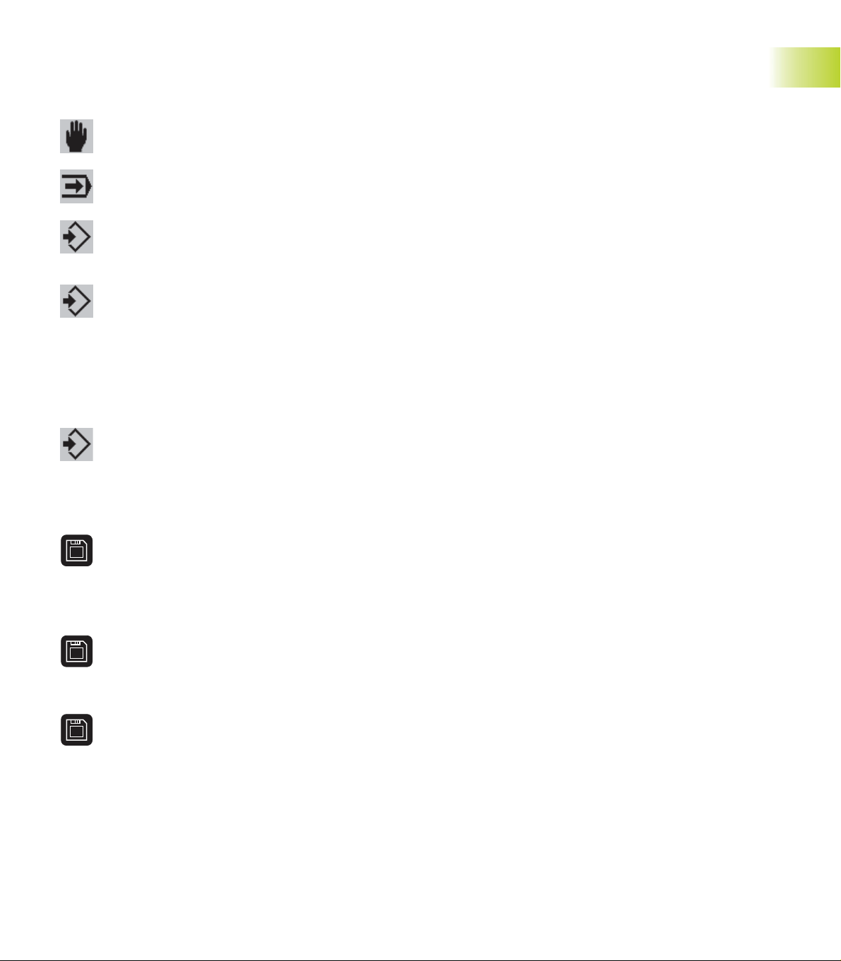
Machine reference points
Machine zero point
The point of intersection of the X-axis with the Z-axis is called the
machine zero point. On a lathe, the machine zero point is usually the
point of intersection of the spindle axis and the spindle surface. The
machine zero point is designated with the letter M.
Workpiece zero point
For machining a workpiece, it is easier to reference all input data to a
zero point located on the workpiece. By programming the zero point
used in the workpiece drawing, you can take the dimensions directly
from the drawing, without further calculation. This point is the
”workpiece zero point.” The workpiece zero point is designated with
the letter W.
Reference marks
Whether the control ”forgets” the positions of the machine axes
when it is switched off depends on the position encoders used. If the
positions are lost, you must pass over the fixed reference points after
switching on the CNC PILOT. The system knows the distances of the
reference points to the machine datum.
1.4 Fundamentals
9HEIDENHAIN CNC PILOT 4290
Page 22

1.5 Tool Dimensions
The CNC PILOT requires information on the specific tools for a variety
of tasks, such as calculating the cutting radius compensation or the
proportioning of cuts.
Tool length
All position values that are programmed and displayed are referenced
to the distance between the tool tip and workpiece zero point. Since
the control only knows the absolute position of the tool carrier (slide),
it needs the dimensions XE and ZE to calculate and display the
position of the tool tip. For milling and drilling tools operating with the Yaxis, the CNC PILOT additionally needs the dimension in Y.
1.5 Tool Dimensions
Tool compensation
The tool tip is subjected to wear during machining processes. To
compensate for this wear, the CNC PILOT uses compensation values.
The system automatically adds the compensation values to the
values for length.
Tooth and cutter radius compensation (TRC)
The tip of a lathe tool has a certain radius. When machining tapers,
chamfers and radii, this results in inaccuracies which the CNC PILOT
compensates with its cutting radius compensation function.
Programmed paths of traverse are referenced to the theoretical tool
tip S. The TRC function compensates for this error by calculating a
new path of traverse, the equidistant line.
Milling cutter radius compensation (MRC)
In milling operations, the outside diameter of the milling cutter
determines the contour. When the MRC function is not active, the
system defines the center of the cutter as reference point for the
paths of traverse. The MRC function compensates for this error by
calculating a new path of traverse, the equidistant line.
1 Introduction and Fundamentals10
Page 23

Basics of Operation
2
Page 24
2.1 User Interface
1
2.1.1 Screen Displays
1 Operating mode line
Show the status of the operating modes.
■ The active mode of operation is shown with a
dark-gray background.
■ Programming and organization modes:
– The selected mode is shown at the right of the
symbol
2.1 User Interface
– Additional information such as the selected program, submode, etc. are shown below the
operating mode symbol.
2 Menu bar and pull-down menus
For function selection
3 Working window
Size and content depend on the operating mode.
Some programming and organization modes
overlap the machine display.
4 Machine display
Current status of the machine (tool position, the
cycle and spindle situation, active tool, etc.). The
machine display is configurable.
5 Status line
■ Simulation, TURN PLUS: display of current
settings or information on the next operating steps
■ Other operating modes: display of the last error
message
6 Calendar date and service ”traffic light”
■ Display of date and time
■ A color background signals a error or a PLC
message
■ The ”service traffic light” shows the servicing
state of the machine (see ”
system”)
7 Soft-key row
Shows the current meaning of the soft keys.
8 Vertical soft-key row
Shows the current meaning of the soft keys. For
more information: see the machine manual
9.3
Maintenance
2
3
4
5
7
8
6
2 Basics of Operation12
Page 25
2.1.2 Controls and Displays
n
Screen with
■ Horizontal and vertical soft keys: The meaning is
shown above or next to the soft keys
Additional keys (same function as on the operating
panel):
■ ESC
■ INS
n
Operating panel with
■ Alphanumeric keyboard with integrated
numeric keypad
■ Keys for Operating mode selection
■ Touch pad: For cursor positioning (menu or soft
key selection, selection from lists, selecting edit
boxes, etc.)
n
Machine operating panel with
■ Operating elements for the manual and
automatic operation of the lathe (cycle keys,
manual direction keys, etc.)
■ Handwheel for exact positioning in manual
operation
■ Override button for feed-rate override
Operation of the touch pad
Normally, you can use the touch pad as an alternative
to the cursor keys. In the following, the keys below
the touch pad are referred to as the left and right
mouse keys.
The functions and operation of the touch pad are
similar to the mouse operation of the Windows
operating systems.
■ Single click of the left mouse key or single touch on
the touch pad:
■ The cursor is positioned in lists or input windows.
■ Menu items, soft keys or buttons are activated
■ Double-click of the left mouse key or double touch
on the touch pad: In lists, the selected element is
activated (the input window is activated)
■ Single-click with the right mouse key:
■ Same function as the ESC key – prerequisite: the
ESC key is allowed in this situation (for example to
go back by one menu level)
■ Same function as the left mouse key when
selection soft keys or buttons
2.1 User Interface
13HEIDENHAIN CNC PILOT 4290
Page 26
2.1.3 Selection of Operating Modes
You can switch the operating mode at any time. After the change, the
new mode starts in the function in which it was last exited.
In the programming and organization modes a difference is made
between the following situations:
■ No operating mode is selected (no entry next to the operating mode
symbol): Select the desired mode from the menu.
■ Operating mode selected (indicated next to the operating mode
symbol): The functions of this operating mode are available. Within
2.1 User Interface
the programming or organization modes, you can switch the modes
by soft key or by repeatedly pressing the corresponding mode key.
2.1.4 Selection of Functions, Data Input
Menu bar and pull-down menu
The individual menu items are preceded by a 9-field symbol with one
field highlighted. This field represents the field on the numeric keypad.
Press the key whose position corresponds to the position of the
highlighted field.
The function selection begins in the menu row, then goes to the pulldown menus. In the pull-down menu, press again the numeric key
assigned to the menu item – or alternatively, select the menu item
with touch pad or with the ”page up/page down” keys and press
Enter.
Soft-key row
The meaning of the soft keys is dependent on the current operating
situation.
Some soft keys work like ”toggle switches”. A function is active when
the associated field in the function-key row is highlighted in color. The
setting remains in effect until the function is switched off.
Keys for operating mode selection:
Manual operating mode
Automatic operating mode
Programming modes
Organization modes
List Operations
DIN PLUS programs, tool lists, parameter lists, etc. are displayed as
lists. You can scroll through a list with the touch pad or arrow keys to
check data, to select the position where you wish to enter data, or to
highlight items for operations like deleting, copying, editing, etc.
After having selected the desired list position or a list item, press the
ENTER, INS, ALT or DEL key to execute the operation.
Continued
2 Basics of Operation14
Page 27

Data Input
Data are entered and edited in input windows. An
input window consists of severalinput fields. You
position the cursor with the touch pad or with the
page up/page down keys to the input box.
Once the cursor is located in the box, you can enter
your data. Existing data are overwritten. With the
right/left arrow keys you can place the cursor on a
position within the input box in order to delete or add
characters. The up/down arrow keys or Enter confirm
and terminate the entry.
Some dialogs have more input fields than a window
can show. In these cases, more than one input
window appears on the screen, one superimposed on
the other. You will recognize this through the window
number in the top line. To toggle between input
windows, use the Page Up/Page Dn keys.
By pressing the ”OK” button, you confirm the data
entered or edited. Independent of the position of the
cursor, you can press the INS key as an alternative. If
you leave the input window by pressing the ”Cancel”
button or the ESC key, entries or changes will be lost.
If the dialog consists of more than one input window,
you already confirm the data when pressing the
PageUp/PageDn key.
Buttons
The CNC PILOT allows you to choose various options
via different buttons such as the ”OK” and ”Cancel”
buttons for terminating a dialog box or the buttons
contained in the ”Extended inputs” window.
Select the required button and press ENTER.
Note: Instead of selecting the ”OK” or ”Cancel”
button, you can press the INS or ESC key.
2.1 User Interface
15HEIDENHAIN CNC PILOT 4290
Page 28

2.2 The Info System
The info system calls excerpts from the User's Manual to the screen. The system is structured in info
topics comparable to the chapters of a book. In the
top line of the information window, the topic you
selected and the page number are shown.
The info system gives you information on the current
operating situation (context-sensitive help). Also, you
can select the info topics through the table of
contents or the subject index. Simply select the
desired topic or word and click ”Topic select” (or
2.2 The Info System
Enter).
Cross references in the text are highlighted. Place
the cursor on the desired cross reference and call the
topic with ”Topic select.” ”Topic return” switches
back to the previous topic.
Error display
When an error message occurs, press the info key, or
place the cursor on the error message in the ”display
of errors” and then press the info key, to get further
information on the respective error.
Call the info system
End the info system
Soft keys
Calls the
■ Selected cross reference
■ Topic from the table of contents
■ Topic from the subject index
Returns to the most recent info topic
Calls the table of contents with the overview of info
topics. The table of contents is arranged in several
levels.
Calls the subject index
Switches to the previous topic.
Switches to the next topic.
(or page up key) previous info page
(or page down key) next info page
2 Basics of Operation16
Page 29
2.3 The Error System
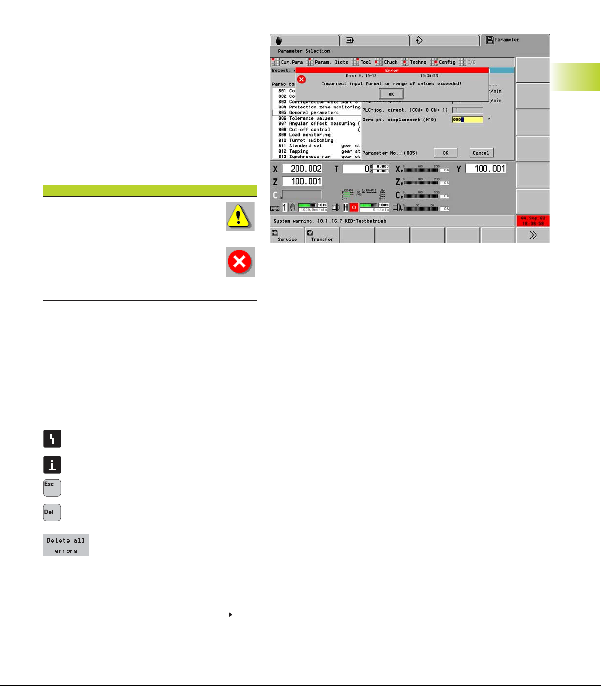
2.3.1 Direct Error Messages
Direct error messages appear whenever immediate
error correction is possible. Confirm the message by
pressing ENTER and correct the error. Example: The
input value of the parameter is out of range.
Information of the error message:
■ Error description: Explains the error
■ Error number: For service inquiries
■ Time of day When the error occurred (for your
information).
Symbols
Warning
The program run/operation continues. The
CNC PILOT indicates the problem.
Error
The program run/operation is stopped. Yo u
must correct the error before you can
continue the current job.
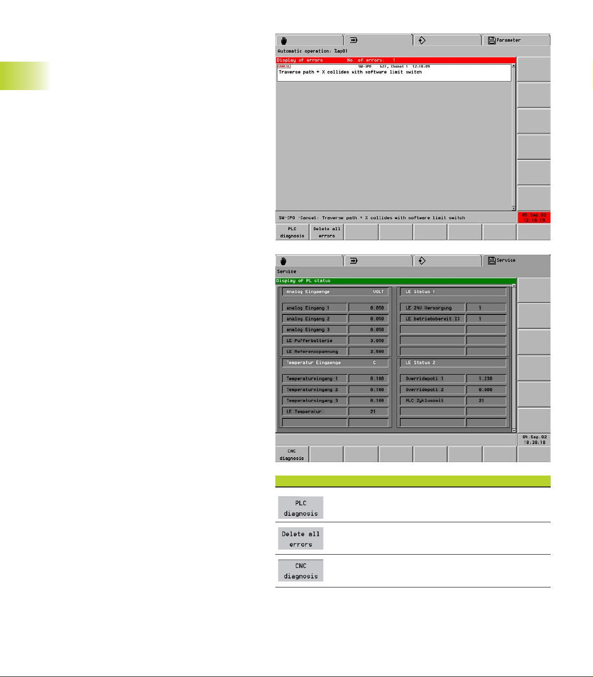
2.3.2 Error Display, PLC Display
Error Display
If during the system start or during program run or
other operation an error occurs, it is indicated in the
date box, displayed in the status line, and saved in
the error display.
The date and time remain highlighted in red until all of
the errors have been canceled.
Notes on using TURN PLUS:
Opens the ”error display”
2.3 The Error System
Further information on the error marked with
the cursor
Exits the error display
Deletes the error message marked with the
cursor
Deletes all error messages.
Continued
17HEIDENHAIN CNC PILOT 4290
Page 30
Information of the error message:
■ Error description: Explains the error
■ Error number: For service inquiries
■ Channel number: Slide for which the error
occurred.
■ Time of day When the error occurred (for your
information).
■ Error class (only with errors):
■ Background: The message serves for
information only, or it is a minor error.
■ Cancel: The running process (cycle run, traverse
command, etc.) was aborted. You can resume
2.3 The Error System
operation once the error has been cleared.
■ Emergency stop: Traverse and the execution of
the DIN program were stopped. You can resume
operation once the error has been cleared.
■ Reset: Traverse and the execution of the DIN pro-
gram were stopped. Switch off the control for a
moment, then restart. Contact your machine
manufacturer if the error occurs again.
System Error, Internal Error
If a system error or internal error occurs, write
down all information on the displayed message and
inform your machine manufacturer. You cannot
correct an internal error. Switch off the control and
restart.
Warnings during Simulation
In the event of problems during simulation of an NC
program, the CNC PILOT displays a warning in the
5.1.2
status line (see ”
Notes on Operation”).
PLC display
The PLC window is used for PLC messages and the
PLC diagnosis. Your machine manual provides more
detailed information on the PLC window.
To call the PLC window, open the error window with
the Error status key and then press ”PLC Diagnosis”
soft key.
To exit the PLC status display, press the ESC key; to
switch to the error window, use the ”CNC Diagnosis”
soft key.
Soft keys
Switch to PLC display
Deletes all error messages
Return to error display
2 Basics of Operation18
Page 31

2.4 Data Backup
The CNC PILOT stores NC programs, operating-resource data and
parameters on the hard disk. Since the possibility of damage to the
hard disk due to excessive vibration or shock cannot be eliminated,
HEIDENHAIN recommends making regular backup copies of your
programs, operating resource data and parameters on a PC.
You can use DataPilot 4290, the WINDOWS ”Explorer” or other
suitable programs for backing up your data on a PC.
For data exchange and data backup, you can use the Ethernet
interface. Data exchange is also possible over the serial interface
(RS-232) (see ”
10.2
Data Transfer Methods”).
2.5 Explanation of Terms
■ Cursor: In lists, or during data input, a list item, an input box or a
character is highlighted. This ”highlight” is called a cursor.
■ Arrow keys: The cursor is moved with the ”page up/page down”
arrow keys or the touch pad.
■ Navigate: You can move the cursor within a list or an input box to
any position you would like to check, change, delete or add to. In
other words, you ”navigate” through the list.
■ Active/inactive functions, menu items: Functions or soft keys
that currently unavailable are shown dimmed.
■ Dialog box: Dialog boxes are also called input windows.
■ Editing: ”Editing” is changing, deleting and adding to parameters,
commands, etc., within programs, tool data or parameters.
■ Default value: If the parameters of DIN commands or other
parameters are preassigned values, these values are referred to as
”default values.”
■ Bytes: The capacity of a storage disk is indicated in ”bytes.” Since
the CNC features a hard disk, the individual program lengths (file
sizes) are expressed in bytes.
■ Extension: File names consist of the actual file name and the ”file
name extension.” The name part and the extension part are
separated by ”.”.The extension indicates the type of file. Examples:
■ ”*.NC” DIN programs
■ ”*.NCS” DIN subprograms
■ ”*.MAS” Machine parameters
2.4 Data Backup; 2.5 Explanation of Terms
19HEIDENHAIN CNC PILOT 4290
Page 32

Page 33

3
Manual Control
and Automatic mode
HEIDENHAIN CNC PILOT 4290
21
Page 34

3.1 Switch-On, Switch-Off,
Reference Run
3.1.1 Switch-On and Traversing the
Reference Marks
In the screen dialog line, the CNC PILOT shows you
step by step how to proceed when starting the
system. The the CNC PILOT asks you to select an
operating mode.
Whether the reference run is necessary depends on
the encoders installed in your machine:
■ EnDat encoder: Reference run is not necessary
■ Distance-coded encoders: The position of the axes
is ascertained after a short reference run
■ Standard encoder: The axes move to familiar,
machine-based points
”Reference automatic” means that all axes make
reference runs. ”Reference jog” only one axis does.
Reference automatic (all axes)
Select ”Ref – Reference automatic.”
<
3.1 Switch-On, Switch-Off, Reference Run
”Status of reference run approach” informs you of
the current status. Axes that have not been
referenced are shown in gray.
<
Either set the slides that need to find a reference or
set ”All slides” (”reference automatic” dialog box)
<
The axis move to find the reference
Interrupts the reference run. Cycle
start resumes the run.
Cancels the reference run
<
After completion of the reference run:
■ The position display is activated.
■ The automatic mode is selectable.
■ The Sequence, in which the axis make their reference
run is defined in machine parameters 203, 253, .. .
■ Exiting the ”Reference automatic” dialog box: Press
Cycle stop
The software limit switches are active only after you
have traversed the reference marks.
Monitoring the EnDat encoders
If your machine is equipped with EnDat encoders, the control saves
the axis positions during switch-off. During switch-on, the CNC PILOT
compares for each axis the position during switch-on with the position
saved during switch-off.
If there is a difference, one of the following messages appears:
■ ”Axis was moved after the machine was switched off.”
Check the current position and confirm it if the axis was in fact
moved.
■ ”Saved encoder position of the axis is invalid”
This message is correct if the control has been switched on for the
first time, or if the encoder or other control components involved
were exchanged.
■ ”Parameters were changed. Saved encoder position of the axis is
invalid.”
This message is correct if configuration parameters were changed.
The cause for one of the messages listed above could be a defect in
the encoder or in the control. Please contact your machine supplier if
the problem recurs.
3 Manual Control and Automatic mode22
Page 35

Reference jog (single axis)
Select ”Ref – Reference jog.”
<
”Status of reference run approach” informs you of
the current status. Axes that have not been
referenced are shown in gray.
<
Set slides and axes (”reference jog” dialog box)
<
The reference run is continued as long
as you keep pressing the key. To
interrupt the reference run, release the
key.
Cancels the reference run
<
After completion of the reference run:
■ The position display is active for the axis that has
been referenced.
■ If all axes have been referenced, you can select
automatic mode.
Exiting the ”Reference jog” dialog box: Press cycle stop
The software limit switches are only active after you
have traversed the reference marks.
3.1 Switch-On, Switch-Off, Reference Run
3.1.2 Switch-Off
Switching off the CNC PILOT. Confirm
the subsequent request with OK. The
control is shut down in an orderly
manner. After a few seconds, CNC
PILOT requests you to switch off the
machine.
”Shutdown” is available in the programming and
organization modes if no operating mode is selected.
Proper switch-off is recorded in the error log file.
HEIDENHAIN CNC PILOT 4290
23
Page 36

3.2 Manual Operating Mode
The Manual control mode offers various functions for
setting up the machine, for measuring tool dimensions
and for manually machining workpieces.
The machine display in the lower section of the
screen shows the tool position and further machine
data.
Options of operation:
■ Manual mode of operation
With the ”machine keys” and the handwheel, you
can control the spindle and move the axes to
machine the workpiece.
■ Setting up the machine
Functions for entering the tools being used, setting
the workpiece zero point, the tool change position,
the protective-zone dimensions, etc.
■ Measuring tool dimensions
Functions for measuring the tool by touching the
workpiece or by use of measuring devices.
■ Configuring the screen display
3.2 Manual Control Operating Mode
The CNC PILOT supports various types of machine
display.
In Automatic mode, the data are entered
and displayed in 1 millimeters or in
inches, depending on the setting of the
control parameter 1.
Remember: If the machine has not been
referenced:
■ The position display is not valid
■ The software limit switches are
nonoperational.
Soft keys
■ Assigns a handwheel to an axis
■ Defines the handwheel interpolation factor
Switches the machine display
Turret one position backward
Turret one position forward
3 Manual Control and Automatic mode24
Page 37

3.2.1 Entering machine data
”F” (feed rate) pull-down menu:
■ Feed per revolution
Select ”Feed per revolut.”
Enter the feed rate in mm/rev (or inches/rev)
■ Feed per minute
Select ”Feed per minute.”
Enter the feed rate in mm/min (or inches/min) and
press OK.
”S” (spindle speed) pull-down menu:
■ Spindle speed
Select ”Speed S.”
Enter the speed in rpm
■ Constant cutting speed
Select ”V constant.”
Enter the cutting speed in m/min (or ft/min) and
press OK.
■ Spindle point stop
To switch to the required spindle, press the
Spindle change key.
Select ”Spindle point stop.”
Enter position
Cycle start: The spindle is positioned
Cycle stop: Exit the dialog box
Menu item ”T” (Tool):
Select ”T”
Enter the turret position
You can enter a constant cutting speed only for slides with
an X axis.
3.2 Manual Control Operating Mode
Tool change functions:
■ Moving the tool into position
■ Offsetting ”new” tool dimensions
■ Showing the ”new” actual values in the position display.
3.2.2 M Commands
”M” (M functions) pull-down menu:
■ The M number is known: Select ”M direct” and
enter the number.
■ M menu: To select the M function, use the menu.
After input/selection of the M function:
Cycle start: The M function is executed
Cycle stop: Exit the dialog box
The content of the M menu depends on
the machine. Yours may differ from the
example shown here.
HEIDENHAIN CNC PILOT 4290
25
Page 38

3.2.3 ManualTurning Operations
”Manual” pull-down menu:
n
Simple longitudinal and transverse turning
operations
Select ”Constant feed.”
Select the direction of feed (”Constant feed”
dialog box).
Control the feed rate with the cycle keys.
n
G functions
Select ”G function.”
Enter the G number and the function parameter;
press OK.
The G function is executed.
The following G functions are permitted:
■ G30 – Rear-face machining
■ G710 – Adding tool dimensions
■ G720 – Spindle synchronization
■ G602..G699 – PLC functions
n
Manual NC programs
Depending on the configuration of a lathe, the
machine manufacturer can includes NC programs
3.2 Manual Control Operating Mode
supporting the machinist in manually operating the
lathe (Example: Switching to rear-face machining).
Refer to the machine manual.
With constant speed, a feed rate per revolution must be
defined.
3.2.4 Handwheel
Assign the handwheel to one of the
principle axes or the C axis, and enter
the feed rate or angle of rotation per
handwheel increment (”Handwheel
axes” dialog box).
The handwheel assignment and speed ratio are
shown in the machine display (the axis letter and the
decimal place of the handwheel traverse ratio are
marked).
The cancel the handwheel assignment, press the
”Handwheel” soft key with opened dialog box.
The handwheel assignment is canceled by:
■ Switching to another slide.
■ Changing the operating mode.
■ Pressing an axis direction key.
■ Selecting the handwheel assignment again.
3 Manual Control and Automatic mode26
Page 39

3.2.5 Spindle and Axis Direction Keys
The keys of the machine operating panel are used for
machining a workpiece manually and for special
functions such as positioning or determining
compensation values (actual position capture,
scratching, etc.).
To activate tools, define the spindle speed and feed
rate, etc., use the menus.
To move the slide diagonally, press the X
and Z-axis direction keys simultaneously.
Spindle keys
Switch the spindle on in M3/M4 direction.
Jog the spindle in M3/M4 direction. The spindle
rotates as long as the key is held. Jog speed:
machine parameters 805, 855, ...
Spindle stop
Axis direction keys (jog keys)
Move slide in X direction.
Move slide in Z direction.
Move slide in Y direction.
3.2.6 Slide/Spindle change key
■ On lathes with more than one slide, the axis
direction keys control the selected slide.
■Selection of the slide: Slide change key
■ Display of the selected slide: Machine display
■ On lathes with more than one spindle, the spindle
keys on the selected spindle.
■ Select the spindle: Spindle change key
■ Display of the selected spindle: Machine display.
■ For setup functions referring to one slide or spindle
(workpiece zero point, tool change point, etc.), you
specify the slide/spindle with the slide/spindle
change key.
■ The machine display usually contains display
elements for spindle and slide. To switch between
these elements, use the Slide/Spindle change key
3.6
(see
”Machine Display”).
To move the slide in rapid traverse: Simultaneously
press the rapid traverse key and the axis direction
key. Rapid traverse velocity: Machine parameters
204, 254, ...
Slide/Spindle change key
Switch over to the next slide
Switch over to the next spindle
3.2 Manual Control Operating Mode
HEIDENHAIN CNC PILOT 4290
27
Page 40

3.3 Tool Lists, Tool Life
Management
The tool list (turret table) indicates the current tool
carrier assignment. To compile a tool list, enter the ID
numbers of the tools.
You can use the entries in the TURRET section of the
NC program to set up the tool list. The ”Compare list”
and ”Accept list” functions refer to the NC program
last interpreted in automatic mode.
Tool life data
Apart from ID numbers and tool type descriptions, the
tool list includes data for tool life management:
■ Status
Shows the remaining tool life/quantity.
■ Ready for use
When the tool life has expired/the defined number
of parts has been produced, the tool is ”not ready
for use” any longer.
■ Atw (replacement tool)
If a tool is ”not ready for use,” a replacement tool is
3.3 Tool Lists, Tool Life Management
inserted.
Simple tools
With the setup functions, you can only enter tools
registered in the database. If the NC program uses
”simple tools,” proceed as follows:: Run an
interpretation of the NC program; the CNC PILOT
automatically updates the tool list.h
If the positions in the tool list are occupied by ”old”
tools, the confirmation request - ”Update tool list?”
- appears. The tools are only entered after you have
confirmed the request.
Tools that are not registered in the database are
identified by the code ”_AUTO_xx” (xx: T number),
and not by an ID number.
■ The parameters of simple tools are defined in the NC
program
■ The tool life data are evaluation only if the tool life
management is active.
Danger of collision
■ Compare the tool list with the current tool carrier
assignment and check the tool data before running a
program.
■ The tool list and the dimensions of the tools entered
must correspond to the actual facts, because the CNC
PILOT uses the data for slide movements, protective-zone
monitoring, etc.
3 Manual Control and Automatic mode28
Page 41

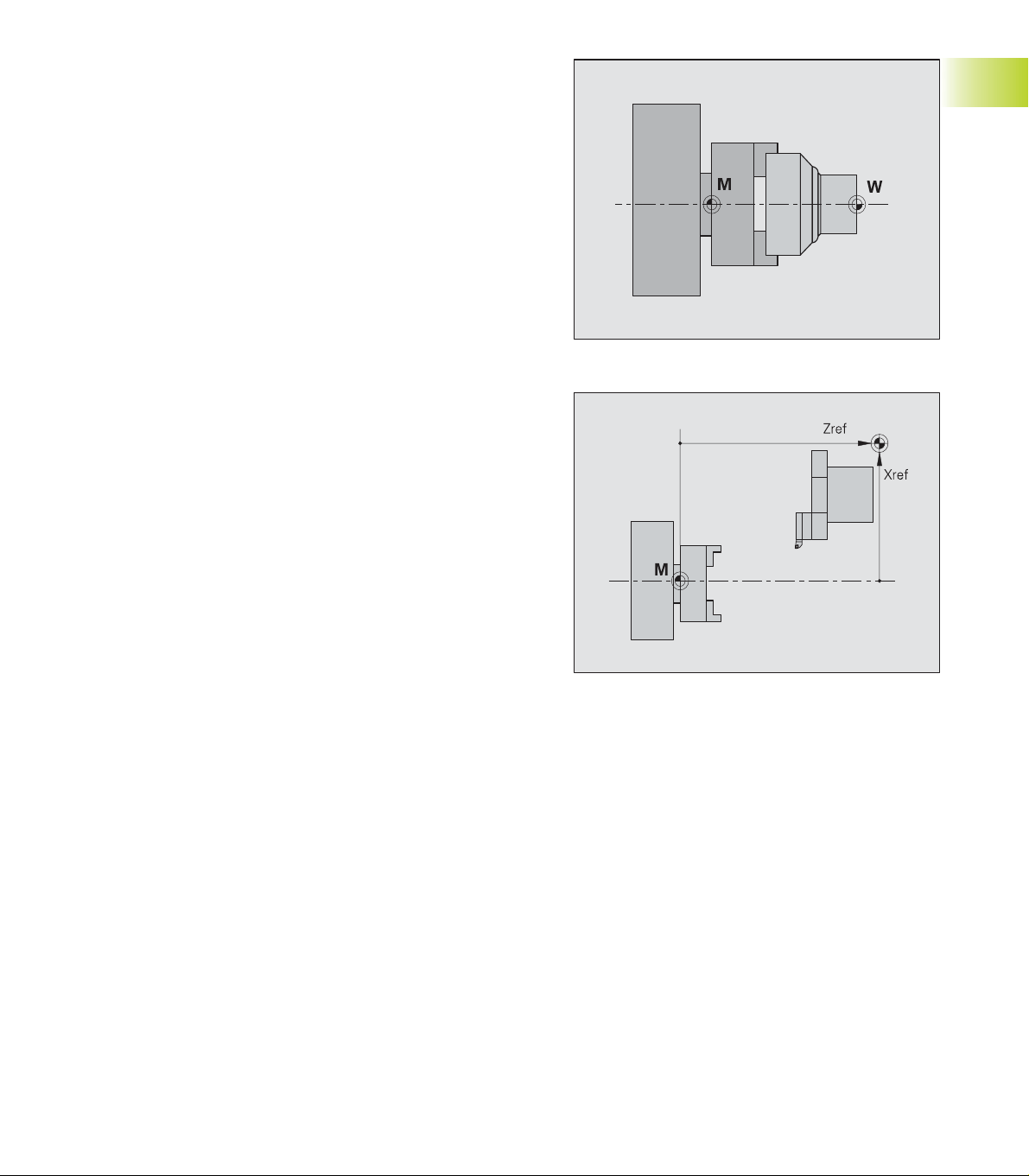
3.3.1 Setting Up a Tool List
A tool list can also be set up without using an NC
program.
Enter a new tool
Select ”Setting up - Tool list - Compile list”
<
Select the tool location
<
ENTER (or INS key) – opens the setup dialog box
<
Enter the ID number
Take the tool from the database
Enter the tool type – the CNC PILOT
displays all tools of this type mask
Enter the ID number – the CNC PILOT
displays all the tools of this ID mask
<
Select the tool
<
Take the tool from the database
3.3 Tool Lists, Tool Life Data
Soft keys
Delete tool
Take the tool from the ”ID number clipboard”
Delete the tool and place in the ”ID number clipboard”
<
Exit the tool database
Delete the tool
Select ”Setting up - Tool list - Compile list”
<
Select the tool location
<
or the DEL key deletes the tool
HEIDENHAIN CNC PILOT 4290
Edit the tool parameters
Entries in the tool database - sorted by tool typep
Entries in the tool database - sorted by tool ID number
Continued
29
Page 42

Changing the tool pocket
Select ”Setting up - Tool list - Compile list”
<
Select tool location
<
Deletes the tool and saves it in the ”ID
number clipboard”
<
Select a new tool location
<
Take the tool from the ”ID number
clipboard”
3.3 Tool Lists, Tool Life Data
If the location was occupied, the
previous tool is taken into the
clipboard.
3 Manual Control and Automatic mode30
Page 43

3.3.2 Comparing a Tool List with an NC
Program
The CNC PILOT compares the current tool list with
the entries in the NC program last translated in
automatic mode.
Comparing a tool list
Select ”Setting up - Tool list - Compare list” The
CNC PILOT shows the current contents of the tool
list and marks deviations from the programmed
tool list.
<
Select marked tool location
<
Nominal-actual comparison
Press ENTER (or INS key). The CNC PILOT opens
the ”nominal-actual comparison” dialog box.
<
Accept the ID number of the ”nominal
tool” in the tool list
or
Look for the tool in the database
3.3 Tool Lists, Tool Life Data
Soft keys
Delete the tool
Take the tool from the ”ID number clipboard”
The CNC PILOT shows the following tools marked:
■ Actual tool ≠ nominal tool
■ Actual – not occupied; nominal – occupied
The entries in the TURRET section are considered
nominal tools (reference:TURRET section of the NC
program most recently interpreted in Automatic
mode).
Tool locations that are not assigned in the NC
program cannot be selected.
Danger of collision
■ Tool pockets that are occupied but,
according to the NC program, are not
needed, are not marked.
■ The CNC PILOT compensates the tool
actually entered – even if it does not
match the nominal assignment.
HEIDENHAIN CNC PILOT 4290
Delete the tool and place in the ”ID number clipboard”
Edit the tool parameters
Entries in the tool database - sorted by tool typep
Entries in the tool database - sorted by tool ID numberr
Accept the ID number of the ”nominal tool” in the tool
list
31
Page 44

3.3.3 Transferring theTool List from an
NC Program
The CNC PILOT transfers the new tool assignment
from the TURRET section (reference: the NC program
last interpreted in Automatic mode).
Transferring the tool list
Select ”Setting up - Tool list - Accept list”
Depending on the previous turret assignment, the
following might occur:
■ Tool not used
The CNC PILOT enters the new tools in the tool list.
Positions that were occupied in the old tool list, but
3.3 Tool Lists, Tool Life Data
are not used in the new list, are retained. If a tool
shall remain in the tool carrier, no further action is
required; if not, delete the tool:
■ Actual tool location differs from location in tool
list
A tool is not entered when its newly assigned
location differs from the location specified in the
tool list. The CNC PILOT displays a message
indicating this error. Change the tool location.
As long as a tool position differs from the nominal
assignment it remains highlighted.
Soft keys
Delete the tool
Take the tool from the ”ID number clipboard”
Danger of collision
■ Tool locations that are occupied but,
according to the NC program, are not
needed, are kept.
■ The CNC PILOT compensates the tool
actually entered – even if it does not
match the nominal assignment.
Delete the tool and place in the ”ID number clipboard”
Edit the tool parameters
Entries in the tool database - sorted by tool typep
Entries in the tool database - sorted by tool ID number
3 Manual Control and Automatic mode32
Page 45

3.3.4 Tool Life Management
The tool life management allows you to define the
sequence of exchange and declare the tool to be
ready for use. The tool life/quantity is defined in the
tool database (see section ”
Life Monitoring”).
The ”Tool life management” dialog box is used both
for entering and displaying the tool life data.
You can use the variable-programming function in
your NC program to evaluate sequential events that
you enter in ”Event 1” and ”Event 2” (see section
4.15.2
V Variables”).
”
Tool life management parameters
■ Repl. tool (replacement tool): T number (turret
position) of the replacement tool
■ Event 1: Sequential event that is triggered when
the life of a tool has expired/a tool has produced the
defined quantity – Event 21..59
■ Event 2: Sequential event that is triggered when
the life of the last tool of the interchange chain has
expired/the tool has produced the defined quantity –
Event 21..59
■ Ready for use: Set the tool to ”ready for use” or
”not ready for use” (applies to tool life management
only).
Entering the tool life parameters
Select ”Setting up – Tool list – Tool life
management”; the CNC PILOT displays the tools
entered.
<
Select the tool location.
<
Press ENTER – the CNC PILOT opens the ”Tool life
management” dialog box.
<
Enter the replacement tool and the tool life
parameters; press OK.
”New cutter” sets the tool life/quantity to the value
programmed in the database and sets the tool to
ready for use.
8.1.7
Multiple Tools, Tool
3.3 Tool Lists, Tool Life Data
Update tool life management data
Select ”Setting up - Tool list – Update tool life management.”
<
Confirm the confirmation request with OK; the CNC PILOT sets the
tool life/quantity to the value defined in the database and sets all
tools in the tool list to ready for use.
<
The CNC PILOT displays the ”Tool list - tool life management” for
inspection.
Application example: The cutting edges of all tools used have been
replaced. Part production is to be continued, using the tool life
management function.
HEIDENHAIN CNC PILOT 4290
33
Page 46

3.4 Setup Functions
3.4.1 Defining the Tool Change Position
With the ISO command G14, the machine slide
moves to the tool change point. Always program
the tool change point as far from the workpiece as
possible to allow the turret to rotate to any position.
Defining the tool change position
For more than one slide: Define the desired slide
(with the Slide change key)
3.4 Setup Functions
<
Select ”Setting up – Tool change point.”
<
The CNC PILOT displays the currently valid position
in the ”Set tool change point” dialog box.
<
Entering the tool change point
Enter a new position
Soft keys
Capture tool change point
Move slide to the tool change position
Confirms the slide position as tool
change point
or
Confirms the position of individual axes
The tool change point is managed in the setup
parameters (Select: „Act. Para – Setting up (menu) –
Tool change point – ..“).
The coordinates of the tool change position
are entered and displayed as distance
between machine datum and tool carrier
datum. Since these values are not shown
in the position display, it is advisable to
move to the tool change point and
”capture” the position.
■ Assigns a handwheel to an axis
■ Defines the handwheel interpolation factor
Switch the machine display
Enter the feed per revolution
Enter the constant surface speed
Enter the M function
Accept the axis position as tool change point(or Y or Z
axis)
Accept the slide position as tool change point
3 Manual Control and Automatic mode34
Page 47

3.4.2 Shifting theWorkpiece Datum
Shifting the Workpiece Datum
For more than one slide: Define the desired slide
(with the Slide change key)
<
Position the tool
<
Select ”Setting up - Shift zero point.”
<
The ”Shift zero point” dialog box displays the
current workpiece zero point.
<
Enter the workpiece zero point
Enter a ”zero point shift”
Contact position = tool zero point
Touch the end face with the tool
Accept the tool contact position as
workpiece zero point
Workpiece zero point relative to the contact
position
Touch the end face with the tool
Accept the tool contact position
3.4 Setup Functions
Soft keys
■ Assigns a handwheel to an axis
■ Defines the handwheel interpolation factor
Switches the machine display
Enter the feed per revolution
Enter the measured value (distance
of the tool contact position from the
workpiece zero point)
The tool zero point is managed in the setup
parameters (Select: „Act. Para – Setting up (menu) –
Tool zero point – ..“).
■ The ”displacement” is with respect to
the machine zero point.
■ You can also offset the workpiece zero
point for the X and Y axes.
HEIDENHAIN CNC PILOT 4290
Enter the constant surface speed
Enter the M function
Define the Z position as tool zero point (or X or Y
position)
Specify the tool zero point relative to the current Z
position (or X or Y position)
35
Page 48

3.4.3 Defining the protection zone
Defining the protection zone
Insert any tool (T0 is not permitted).
<
Select ”Setting up - Selection zones”
<
Enter the protection zone parameters
Enter the limit values.
3.4 Setup Functions
Capturing the protection zone parameters per
axis
For each input box:
Select the input field
Position the tool to the protection zone limit
Accept the axis position as protection
zone parameter
Capturing positive/negative protection zone
parameters
Select any positive or negative input field
Position the tool to the protection zone limit
Accept all positive/negative axis
positions
Soft keys
■ Assigns a handwheel to an axis
■ Defines the handwheel interpolation factor
Switch the machine display
Enter the feed per revolution
The parameters serve for protection zone
monitoring - not as software limit switches.
Protection zone parameters:
■ are expressed with respect to the
machine zero point
■ are managed in the machine parameters
1116, 1156, ..
■ X value are radius dimensions
■ 99999/–99999 means: no monitoring of
this side of the protection zone
Enter the constant surface speed
Enter the M function
Accept the X position as ”protection zone –X”
parameter (or +X, –Y, +Y, –Z, +Z position)
Accept the axis positions as positive/negative
protection zone parameter
3 Manual Control and Automatic mode36
Page 49

3.4.4 Setting up the ChuckingTable
The chucking table is evaluated by the concurrent
graphics.
Setting up the chucking table
Select ”Setting up – Chucking table – Main spindle
(or Tailstock)
<
Select the ID number from the chucking database
Chucking equipment for spindles
The definition of the clamping form (”Grip. form”)
presupposes the definition of the chuck jaws. Set the
clamp form by soft key – it is graphically illustrated.
To switch to the chucking assignment of further
spindles, press the Page Up/Page Dn keys.
Parameters for ”spindle x” (main spindle, spindle 1, ..)
■ Chucking ID (identification number): Reference to
database.
■ Chuck jaws ID (identification number): Reference to
database.
■ Chuck supplement ID (identification number):
Reference to database.
■ Clamp form (for chuck jaws): Define internal/
external chucking and the level of chuck jaws used
■ Clamping diameter: The diameter at which the
workpiece is clamped. (Workpiece diameter when
clamped externally; inside diameter when internal
clamping is used)
”Tailstock” parameters
■ Sleeve center ID (identification number): Reference
to database.
3.4 Setup Functions
Soft keys
Edit the chucking equipment parameters
Entries in the chucking database – sorted by chuck type
Entries in the chucking database – sorted by chuck ID
number
”Continue” – Define the clamp form
HEIDENHAIN CNC PILOT 4290
37
Page 50

3.4.5 Setting up Machine Dimensions
You can evaluate machine dimensions in the variable
programming of the NC program.
The ”Set machine dimensions” function accounts for
the dimensions 1..9 and the ”configured axes” for
each dimension.
Setting up machine dimensions
Select ”Setting up - Machine dimensions.”
<
3.4 Setup Functions
Enter the machine dimension number
<
Enter the machine dimensions
Enter the values (”Set machine dimension x” dialog
box).
Capturing a single machine dimension
Select the input field
Move the axis to the desired position
Confirm the axis position as machine
dimension (or Y or Z position)
Soft keys
■ Assigns a handwheel to an axis
■ Defines the handwheel interpolation factor
Capturing all machine dimensions
Move the slides to the desired positions
Confirm the axis positions of the slides
as machine dimensions
<
OK – enter the next machine dimension
Cancel – Exit the machine dimension setup
Machine dimensions are managed in machine
parameter 7.
Machine dimensions are given with
respect to the machine zero point.
Switch the machine display
Enter the feed per revolution
Enter the constant surface speed
Enter the M function
Accept the axis position as machine dimension X (or Y or
Z axis)
Accept the axis positions of the slides as machine
dimensions
3 Manual Control and Automatic mode38
Page 51

3.4.6 MeasuringTools
Define the type of tool measurement in machine
parameter 6:
■ 0: Contact with tool
■ 1: Measure with touch probe
■ 2: Measure with measuring optics
MeasuringTools
Position the tool
<
Select ”Setting up - Tool setup – Tool measuring.”
The ”Tool measuring T...” dialog box indicates the
current tool dimensions.
<
Enter the machine dimensions
Enter the dimensions
Find the tool dimensions by touching the
workpiece with the tool
Select the input field ”X”
Touch off the diameter, retract in Z direction
Confirm the diameter as measured
value
Select the Z input field
Touch the face with the tool, then retract in the X
direction
Confirm the Z position of the tool as the
measured value
3.4 Setup Functions
Soft keys
■ Assign a handwheel to an axis
■ Define the handwheel interpolation factor
Switch the machine display
Enter the feed per revolution
Enter the constant surface speed
Measuring tools with the touch probe
for each input field:
Select the X/Z input field
Move the tool tip in X/Z direction to the probe; the
CNC PILOT saves the X/Z dimension
Retract the tool – retract the touch probe
Measuring the tools with measuring optics
For each input field
Select the X/Z input field
Align the tool point in the X/Z direction with the
cross hairs
Accept the value
HEIDENHAIN CNC PILOT 4290
Enter the M function
Accept the X position as measured value X (or Y or Z
position)
■ The entries in the ”Enter measured value” dialog box are
given with respect to the workpiece zero point.
■ The compensation values of the tool are deleted.
■ The measured tool dimensions are entered in the
database.
Continued
39
Page 52

Determining tool-compensation values
Move the tool into position
<
Select ”Setting up - Tool setup – Tool compensation”
<
Assign the handwheel to the X axis – move the tool
by the compensation value
<
Assign the handwheel to the Z axis – move the tool
by the compensation value
3.4 Setup Functions
<
The CNC PILOT loads the
compensation values
Soft keys
■ Assign a handwheel to an axis
■ Define the handwheel interpolation factor
Switch the machine display
Enter the feed per revolution
Enter the constant surface speed
Enter the M function
Accept the tool compensation values
3 Manual Control and Automatic mode40
Page 53

3.5 Automatic Mode of
Operation
In Automatic mode, the data are entered
and displayed in 1 millimeters or in
inches, depending on the setting of the
control parameter 1. The setting in the
”program head” of the NC program
governs the execution of the NC part
program - it has no influence on operation
or display.
3.5.1 Program Selection
The CNC PILOT interprets the NC program before it
can be activated with Cycle Start. ”#-Variables” are
entered during the translation process. A ”restart”
prevents a new translation, while a ”new start”
forces a new translation.
Program selection
Select ”Prog – Program selection”
Select the NC program
The NC program is loaded without previous
translation, if:
■ No changes were made in the program or the tool
list.
■ The lathe was not switched off since the program
was last selected.
Restart
Select ”Prog – Restart”
The last active NC program is loaded without
without previous translation, if:
■ No changes were made in the program or the tool
list.
■ The lathe was not switched off since the program
was last selected.
New start
Select ”Prog – New start”
The NC program is loaded and translated. (Use for
starting an NC program containing # variables.)
From DIN PLUS
Select ”Prog – From DIN PLUS”
The NC program selected in DIN PLUS is loaded
and translated.
■ If the ”turret table” of the NC program is
not the currently valid one, there is a
warning.
■ The name of the NC program is retained
until you select another program – even if
the lathe was switched off in the
meantime.
3.5 Automatic Mode of Operation
Soft keys
Switch to ”graphic display”
Switch the machine display
Define block display for more channels
Display basic blocks (individual paths of traverse)
Suppress/permit variable output
Set single block mode
Program stop at M01 (optional stop)
Run a start-block search
HEIDENHAIN CNC PILOT 4290
41
Page 54

3.5.2 Defining a Start Block
Defining a Start Block
Activating a start block search
<
Position the cursor on the start block. (The soft
keys support your search.)
<
The CNC PILOT switches back into
automatic mode and jumps to the start
block.
<
Start the NC program with the selected
NC block.
3.5 Automatic Mode of Operation
Exit the start block search without default
start block.
■ Select a suitable start block. If program
run is started by a specific start block, the
CNC PILOT automatically provides all the
programmed and essential data for this
NC program (excluding interchange of the
correct tool and paths of traverse).
■ On machines with more than on slide,
select a suitable start block on all slides
before you press the Accept soft key.
Danger of collision
■ If the start block includes a T command,
the CNC PILOT first rotates the turret.
■ The first traversing instruction is
executed from the current tool position.
Soft keys
Switch the machine display
Define block display for more channels
Display basic blocks (individual paths of traverse)
Preset the T number – the cursor is positioned with this
T number on the next T command
Preset the T number – the cursor is positioned to the
block number
Preset the L number – the cursor is positioned with this
L number to the next subprogram call
Run a start-block search
3 Manual Control and Automatic mode42
Page 55

3.5.3 Program Sequence Modification
Skip levels:
■ The program blocks which are marked as active
skip levels are not executed when the program is
being carried out.
■ Skip levels: 0..9
■ For multiple skip levels, enter a sequence of digits
■ Deactivate the skip level: No entries in ”Level No.”
Operation:
Select menu item ”Process - Skip level”
Enter the level number
Quantity
■ Counting range: 0..9999
■ Quantity = 0: Production without quantity limitation;
the counter is increased by one after each program
run.
■ Quantity > 0: The CNC PILOT produces the defined
quantity; the counter is reduced by one after each
program run.
■ Quantity counting is retained even if the machine
has been switched off in the meantime.
■ When an NC program is activated with ”Program
selection,” the CNC PILOT resets the quantity
counter.
■ When a program has completed a production lot,
the NC program cannot be restarted by the Cycle
Start key. To start the NC program again, press
”Re-start.”
Operation:
Select menu item ”Process – Quantity”
Enter the quantity
V variables
■ The ”V variables” dialog box serves for input and
display of variables.
■ V variables are defined at the beginning of the NC
program. The meaning is specified in the NC
program.
Operation:
Select the menu item ”Process – V variables” –
the CNC PILOT shows the variables defined in the
NC program
Press ”Edit” if you wish to change the variables
Status of skip levels
Display field:
Markings:
■ Upper row: entered skip levels
■ Lower row: the skip levels detected by the ”block execution”
(active skip levels)
The CNC PILOT accounts for activated/deactivated skip
levels after approx. 10 blocks (reason: block scan during
the execution of NC blocks).
3.5 Automatic Mode of Operation
HEIDENHAIN CNC PILOT 4290
Continued
43
Page 56

Single-block mode
Only one NC command (basic block) is
executed at a time. The CNC PILOT
then goes into the ”cycle stop”
condition.The subsequent blocks are
started with Cycle Start.
Optional STOP
The CNC PILOT stops at the M01
command and goes into the cycle stop
condition. Cycle start resumes the
program run.
Status of optional stop
Optional stop off
Optional stop on
Feed rate override F% (0% .. 150%)
Feed rate override is controlled manually with a knob
on the on the machine operating panel. The machine
display shows the current feed rate override.
Spindle speed override S% (50% .. 150%)
The spindle speed override or the reset to the
3.5 Automatic Mode of Operation
programmed speed is controlled with the keys of the
machine operating panel. The machine display shows
the current spindle speed override.
3.5.4 Compensation
■ Tool compensation
Select ”Comp - Tool compensation”
The CNC PILOT enters the T number and current
compensation values of the active tool. You can
enter a differentT number.
Enter the compensation values
Values entered here are added to the existing
compensation values.
Tool compensation:
■ Become effective when the next
traverse starts.
■ Are transferred to the database.
■ Values of max. 1 mm can be entered.
Keys for spindle speed override
Rotational speed to 100% (of the programmed value)
Increase speed by 5%
Reduce speed by 5%
3 Manual Control and Automatic mode44
Page 57

■ Additive compensation
Select ”Comp - Additive cormpensation.”
Enter the compensation number (901 to 916); the
CNC PILOT displays the current compensation
values.
Enter the compensation values
Values entered here are added to the existing
compensation values.
Additive compensation:
■ are activated with G149 ..
■ are managed in setup parameter 10
■ can be changed by no more than 1 mm
3.5 Automatic Mode of Operation
3.5.5 Tool Life Management
Select ”Comp - Tool life management.”
This tool list with the current tool life data is
displayed
Select the tool
ENTER opens the ”Tool life management” dialog
box
■ Set to ”ready for use” - or
■ update the tool life data with a ”new cutter.”
HEIDENHAIN CNC PILOT 4290
45
Page 58

3.5.6 Inspection Mode
This function interrupts the program sequence,
checks and corrects the ”active tool,” inserts a new
cutting edge and continues the NC program from the
point of interruption.
The inspection cycle is executed as follows::
Interrupt the program sequence and retract the
tool.Check the tool, and replace the cutting edge if
necessary.n Return the tool.
■ Cutting edge OK: Continue the automatic
program run.
■ New cutting edge: Define the compensation
values by ”scratching,” and continue the automatic
program run.
When the tool is retracted, the CNC PILOT stores the
first five traverse movements. Each change in
direction corresponds to a path of traverse.
The NC program run can be continued before the
point of interruption. Specify the distance to the
3.5 Automatic Mode of Operation
interruption point. If the value is greater than the
distance between the start of the NC block and the
interruption point, program sequence begins at the
start of the interrupted NC block.
■ During the inspection process you can
turn the turret, press the spindle keys, etc.
■ If the turret was turned, the return
motion program inserts the ”correct” tool.
■ When changing the cutting edge, select
the compensation values so that the tool
stops in front of the workpiece.
■ In the cycle stop condition you can
interrupt the inspection cycle with ESC and
switch to ”Manual control.”
Inspection mode
Interrupt the program run
<
Select ”Insp(ection)”
<
To retract the tool, use the axis-direction keys.
<
If necessary, swivel the turret.
<
Inspect the tool; if necessary, replace it.
<
Conclude the inspection process - the CNC PILOT loads
the return motion program (”_SERVICE”).
<
The ”Tool compensation” dialog box appears. Enter the
compensation values, and confirm with OK.
If you are using a new cutting edge, modify the tool compensation
so that the tool - when returning - comes to a stop in front of the
workpiece.
<
If necessary, activate the spindle.
<
Starts the return motion program.
<
Continued
3 Manual Control and Automatic mode46
Page 59

Inspection mode – continued
The ”Scrambled takeoff on restart?” dialog box
appears; Enter Yes/No, and press OK.
<
Scrambled takeoff – Yes:
The ”Start from interruption point (IP) / before
interruption point” dialog box appears.
■ From UP: No further dialog box.
■ Before UP: Specify the distance from the point of
interruption to the starting point of the tool (Dialog
”Distance from interruption point”).
The return motion program positions the tool on/
before the interruption point and continues the
program without stopping.
The inspection cycle has been completed.
Scrambled takeoff – NO:
The ”Start from interruption point (IP) / before
interruption point” dialog box appears.
■ From UP: No further dialog box.
■ Before UP: Specify the distance from the point of
interruption to the starting point of the tool (Dialog
”Distance from interruption point”).
The return motion program positions the tool on/
before the interruption point and stops.
Application example: Cutting edge has been
replaced.
<
Select ”Insp(ection)” again.
<
The ”Scratch with tool” dialog box opens (for
information)
<
Assign the handwheel to the X/Z axis and
”scratch” the workpiece.
<
Press ”Accept value” to save the compensation
values defined per handwheel.
<
The program run continues
3.5 Automatic Mode of Operation
HEIDENHAIN CNC PILOT 4290
47
Page 60

3.5.7 Block Display
Block display – basic block display
The block display lists the NC blocks according to
the programmed sequence. The basic-block display
shows the individual paths of traverse – the cycles
are ”resolved.” The numbering of the basic blocks is
independent of the programmed block numbers.
In the block display and basic-block display, the cursor
is located on the block being executed.
Channel display
For lathes with several slides (channels), you can
activate block display for up to 3 channels.
Basic block on/off
Switching the channel display
To add a channel, press the soft key
again; in the block display, only channel
3.5 Automatic Mode of Operation
Menu item ”display - ...”
■ Font size: Enlarges/reduces the characters in the
block display
■ Load monitoring – see ”
Load Monitoring”
1 is shown.
Variable output
Pressing the soft key enables the
variable soft key output (with PRINTA).
Otherwise the variable output is
suppressed.
3.7.2
Production under
3 Manual Control and Automatic mode48
Page 61

3.5.8 Graphic Display
The ”Automatic graphics” function displays the
programmed blank and finished part and the paths of
traverse. This enables process control of non-visible
areas during production and provides an oversight of
production status, etc.
All machining operations, including milling, are
depicted in the turning window (XZ view).
Activate the graphic – if the graphic
was already active, the screen is
adapted to the current machining
status.
Return to block display
Settings:
Line: Each tool movement is
represented as a line, referenced to the
theoretical tool tip.
Cutting path: depicts the surface
covered by the ”cutting area” of the
tool with hatch marks. You can see the
area that will actually be machined,
with the geometry of the respective
tool already accounted for (see ”
5.1
Simulation Mode of Operation”).
The white dot: (small white rectangle)
represents the theoretical tool point.
Tool: The tool contour is depicted.
(Precondition: Proper tool description in
the tool database.)
Standard: The system displays the
complete path of traverse block by
block
Motion: Depicts the metal removal in
synchronism to the machining
sequence.
Prerequisites:
■ Workpiece blank is programmed
■ Activate the ”motion” function
before starting the NC program.
■ If an NC program is repeated (M99),
the ”Motion” function becomes active
with the next program run.
3.5 Automatic Mode of Operation
Soft keys
Return to block display
Activate the zoom function
Set to Single block mode
Depiction of traverse paths: Line or (cutting) trace
Tool depiction: Point of light or tool
■ ”Motion” appears only for lathes with one slide.
■ If no blank part was programmed, the standard blank
form (control parameter 23) is assumed.
HEIDENHAIN CNC PILOT 4290
Continued
49
Page 62

Enlarging, reducing, selecting a section for
enlargement
When you call the zoom function, a red
frame appears with which you can
select the detail you wish to isolate.
Detail:
■ Enlarge: ”Page forward”
■ Reduce: ”Page back”
■ Shift: Cursor keys
Zoom settings by touch pad
Prerequisite: Simulation in ”stop condition”
Position the cursor to one corner of the section
While holding the left mouse key, pull the cursor to
the opposite corner of the section
Right mouse key: Return to standard size
Standard settings: See soft-key table
3.5 Automatic Mode of Operation
Exit the zoom function
After having enlarged a detail to a great extent, select
”Workpiece maximum” or ”Work space,” and then
isolate a new detail.
Soft keys
Return to block display
Cancels the zoom settings last used and displays the
last standard setting (”Workpiece maximum” or ”Work
space”).
Switches back to the last zoom/setting used. You can
select ”Previous zoom” more than once.
Shows the workpiece in the largest possible
magnification
Shows the working space including the tool change
position.
In the ”Coordinate system” dialog box, you specify the
dimensions of the simulation window and the position of
the workpiece zero point.
3 Manual Control and Automatic mode50
Page 63

3.5.9 Post-Process Measuring Status
Display
Selection: Menu item ”Display – PPM Status”
(automatic mode)
The ”PPM Info” dialog box contains information on
the status of the measured values and displays the
transferred results:
■ ”Measured-value coupling” (control parameter 10)
■ Off: Measuring results are immediately
transferred. Previous values are overwritten.
■ On: Measuring results are not transferred until
the previous results have been processed.
■ Measured values valid: Status of the measured
values (after the measured values have been
transferred with G915, the status ”No” is
displayed).
■ #939: Total result of last measurement.
■ #940..956: Measuring results last transferred by the
measuring function.
If you select ”Init,” the post-process measuring
function is re-initialized and all measured values are
deleted.
3.5 Automatic Mode of Operation
The post-process measuring function stores the measured
values received in the clipboard. The ”PPM Info” dialog box
displays in #939..956 the values contained in the clipboard not the variables.
HEIDENHAIN CNC PILOT 4290
51
Page 64

3.6 Machine Display
The machine display of the CNC PILOT can be
configured. Per slide, you can configure up to 6
displays in Manual mode and Automatic mode.
Switches to the ”next configured
display”
To switch to the display of the following
slide, press the Change slide key. With
the spindle change key you can display
the next spindle.
3.6 Machine Display
The ”display elements” table explains the standard
display fields. For more display fields, see ”
Parameters”
You can set the values of the Position
display in ”Display setting” (machine
parameter 17):
■ 0: Actual values
■ 1: Lag
■ 2: Distance to go
■ 3: Distance between tool tip and position
of slide
■ 4: Slide position
■ 5: Distance between reference cams
and zero pulse
■ 6: Nominal position value
■ 7: Distance between tool tip and slide
position
■ 8: IPO nominal position
7.3
Control
Display elements
Position display (actual value display)
Distance from tool point to tool zero point
■ Empty box: Reference mark in this axis not yet traversed
■ White axis letter No enabling
Position display (actual value display) C
Position of the C axis.
■ ”Index”: Indicates the C axis „0/1“
■ Empty box: C axis is not active
■ White axis letter: No enabling
Distance-to-go display
Distance remaining in the current traverse command
■ Bar graphic: Distance to go in millimeters
■ Box at lower left: Actual position
■ Box at lower right: Distance to go
T display – without tool life monitoring
■ T number of active tool
■ Tool compensation values
T display – with tool life monitoring
■ T number of the active tool
■ Tool life data
Continued
3 Manual Control and Automatic mode52
Page 65

Display elements (continued)
Cycle status (slide display)
Quantity of workpieces/time per workpiece
■ Number of finished workpieces in this batch
■ Machining time of current workpiece
■ Entire production time of this batch
Load display
Load of the spindle motors/axis drives with regard to rated torque
D display – additive compensation
■ Number of the active compensation
■ Compensation values
Slide display
■ White symbol: No enabling
■ Number: Selected slides
■ Cycle state: see table
■ Bar diagram: Feed rate override ”in %”
■ Upper box: Feed rate override
■ Lower box: Current feed rate – with stationary spindle: Nominal
feed rate (gray print)
■ Slide number in blue background: Rear side machining active
Spindle display
■ White symbol: No enabling
■ Number in spindle symbol: Gear range
■ ”H”/number: Selected spindle
■ Spindle status: See table
■ Bar diagram: Spindle speed override ”in %”
■ Upper box: Spindle speed override
■ Lower box: Current speed – with position control (M19): Spindle
position – with stationary spindle: Nominal speed (gray print)
Automatic mode – Cycle Start
Automatic mode – Feed Stop
Automatic mode – Cycle Stop
Manual control
3.6 Machine Display
Inspection cycle
Machine in setup mode
Spindle status (spindle display)
Direction of spindle rotation M3
Direction of spindle rotation M4
Spindle stopped
Spindle position-controlled (M19)
C-axis is ”active”
Overview of enabled elements
Shows the enabling status of up to 6 NC channels, 4 spindles, and 2
C-axes. Enabled elements are marked in green.
■ Display group at left: Enabled elements
F=feed rate; D=data; S=spindle; C=C-axis.
1..6: Number of slides/ of spindle, of C axis
■ Display group at center: Status
Zy – left dash: Cycle on/off.
Zy – right dash: Feed Stop.
R=traversing the reference marks; A=automatic mode;
H=manual control;
F=retracting (after traversing the limit switches);
I = Inspection mode; E = Setup switch;
■ Display group at right: Spindle
Display for ”direction of rotation left/right.”
Both active: Positioning of spindle (M19).
HEIDENHAIN CNC PILOT 4290
53
Page 66

3.7 Load Monitoring
The load monitoring function of the CNC PILOT
compares the current torque, or the values for work,
with the values from a ”reference run.”
If ”torque limit 1” or the ”work limit” is exceeded, the
CNC PILOT marks the tool as ”worn out.” If ”torque
limit 2” is exceeded, the CNC PILOT assumes tool
breakage and stops machining (feed stop). Violations
of limit values are reported as error messages.
The load monitoring identifies worn tool in the ”tool
diagnosis bits.” If you are using the tool life
3.7 Load Monitoring
management function, the CNC PILOT will manage
4.2.4
the replacement of tools (see ”
Programming”). You can also evaluate the ”tool
diagnosis bits” in the NC program.
The load monitoring function defines the monitoring
zones and the drives to be monitored (G995) in the
NC program. The torque limits of a monitoring zone
depend on the maximum torque determined by the
reference machining cycle.
Tool
The CNC PILOT checks the values for torque and work in each
interpolator cycle and displays the values in a time reference grid of
20 ms. The limit values are calculated from the reference values and
the limit factor (control parameter 8). You can later change the limit
values in ”Edit load parameters.”
■ Make sure that the conditions for reference machining
comply with those for production (feed-rate/speed override,
tool quality, etc.).
■ Up to four components are monitored per monitoring
zone.
■ Using ”G996 Type of load monitoring,” you can control
the hiding the rapid traverses paths and the monitoring of
torque and/or work.
■ The graphic and numeric displays are relative to the rated
torque values.
3.7.1 Reference Machining
The reference machining cycle (registration of nominal
values) determines the reference values for the
maximal permissible torque and work of each
monitoring zone.
CNC PILOT executes a reference machining cycle if:
■ The parameters for monitoring have not been
entered.
■ You press ”Yes” in the ”Reference machining”
dialog box (after having selected the program).
Selection: ”Display – Load monitoring – Load
monitoring display” (Automatic mode).
”Taking nominal values” submenu
■ ”Curves” menu item
Assign the input fields ”curves 1...4” to the drives.
The value in ”Display grid” influences the accuracy
and velocity of the graphical display. A small value
increases the accuracy of the display (values: 4, 9,
19, 39 seconds per image).
■ ”Mode” menu group
■ Line graphics: Display torque values over the
time axis
Continued
3 Manual Control and Automatic mode54
Page 67

■ Bar graphic: Graphically display torque values
and mark the peak values
■ Save/do not save measured values
The measured values must be saved for later
analysis of reference machining. Check the setting
in the ”Save data” (”Write data”) display field.
■ Overwrite/Do not overwrite limit values
If you wish to retain the limit values after a new
reference machining cycle, select ”Do not
overwrite limit values.”
■ Pause stops the display
■ Continue continues the display
■ Auto: returns to the automatic menu
Additional information
■ Zone number: Current monitoring zone.
Negative algebraic sign: Production is not
monitored (example: skipping the paths of rapid
traverse).
■ Tool: Active Tool.
■ Selected drives: The drives are listed and the
current torques are displayed.
■ Block display
3.7 Load Monitoring
Block display has no influence on reference machining.
3.7.2 Production Using Load Monitoring
If you wish to use the load monitoring function for
your machining processes, you must activate it in the
NC program (G996).
Display torque values and limit values:
”Display – Load monitoring – Display” (Automatic
operating mode).
”Load monitoring display” submenu:
■ ”Curves” menu item
Enter the required drives in the input fields ”Curves
1 to 4”.
■ Line graphics: One curve
■ Bar graphics: Up to four curves
Display grid: See §
■ ”Mode” menu group
■ Line graphic Display the torque values over the
time axis and limit values – limit values are gray:
nonmonitored area (rapid traverse paths are
hidden).
■ Bar graphic Displays current torque values,
previous ”work” and all limit values of the
monitoring zone
3.7.1
Reference Machining”
■ Pause Stops the display
■ Continue Resumes the display
■ Auto Returns to the automatic menu
HEIDENHAIN CNC PILOT 4290
55
Page 68

3.7.3 Editing Limit Values
The function for editing the load parameters allows
you to analyze reference machining cycles and
optimize limit values.
The CNC PILOT displays the program name of the
loaded monitoring parameters in the header.
Selection: ”Display – Load monitoring – Edit”
(Automatic mode).
3.7 Load Monitoring
”Load parameter editor” submenu
■ ”Act. load” (Load current file) menu item:
Monitoring parameters of the active NC program.
■ ”Load” menu item: Monitoring parameters you
have selected.
■ ”Edit” menu item: Display and edit the limit
values.
■ ”Delete reference values” menu item: Delete the
load parameters of the NC program.
■ Auto Returns to the automatic menu
Editing the load parameters
The ”Display and adjust load parameters” dialog box
displays the parameters of one component of one
monitoring zone, which can then be edited.
The bar graphic shows all components of the
monitoring zone (the larger bar displays the values for
performance; the smaller bar displays the values for
work). The selected component is highlighted.
Enter the monitoring zone and select the component.
The CNC PILOT displays the reference values. The
limit values for performance and work, which are
displayed, can be edited. The tool (T number) is
displayed for information.
Buttons of the dialog box:
■ Saving: Store the limit values of the component in
the specified zone.
■ End (or ESC key): Exit the dialog box.
■ File: Switch to ”Line graphics.” Precondition: The
values measured during the reference machining
cycle have been stored.
3 Manual Control and Automatic mode56
Page 69

3.7.4 Analyzing Reference Machining
The torque and the limit values of the selected
component are shown ”over time.” Limit values
”gray”: nonmonitored area (hiding rapid traverse
paths).
The CNC PILOT also displays the values of the cursor
position.
Selection: ”File” button (”Display and set load
parameters” dialog box).
”Analyzer (file display)” submenu:
■ ”Set cursor” pull-down menu; using the right/left
arrow key, position the cursor at the:
■ Start of file
■ Start of the next zone
■ Zone maximum
■ ”Display” menu item: Select the component from
the ”Display file” dialog box.
■ ”Setting – Zoom” menu item: Set the zoom
factor. (Small values increase the accuracy of the
display and reduce the step size of the cursor.)
The settings defined for the grid, the time reference
grid of the measured value registration and the
cursor position are shown in the line below the
graphic display (relative to the start of reference
machining). Time ”0:00.00 sec” = Start of reference
machining cycle.
Switch back to ”Edit load parameters”
3.7 Load Monitoring
3.7.5 Machining Using Load Monitoring
It is advisable to use the load-monitoring function
when - due to a dull cutting edge - a machining
process requires a considerably higher torque than
with a new cutting edge. As a rule, drives that are
subjected to considerable loads should be monitored usually the main spindle.
Due to the relatively small torque variations, it is
difficult to monitor machining operations with small
cutting depths.
A decrease in torque cannot be identified.
HEIDENHAIN CNC PILOT 4290
Defining the monitoring zones: The reference values for torque
depend on the maximum torque values of the zone. Therefore, lower
torque values cannot always be monitored.
Facing with constant cutting speed: The spindle is monitored as
long as the acceleration is 15% of the mean value from maximum
acceleration and maximum braking deceleration (machine parameters
811, ...). Since acceleration increases as a result of the increase in
rotational speed, the CNC PILOT usually only monitors the period after
the first cut.
Experimental values for the machining of steel
■ For longitudinal turning, ensure that the cutting depth is greater than
1 mm.
■ For recessing, ensure that the cutting depth is greater than 1 mm.
■ For hole drilling, ensure that the diameter drilled is between 6 and
10 mm.
57
Page 70

3.7.6 Load Monitoring Parameters
Machine parameters for load monitoring (spindle: 809, 859, ...; C-
axis: 1010, 1060; linear axes: 1110, 1160, ...)
■ Start time for monitoring [0 to 1000 ms] is calculated when rapid
traverse movements have been skipped:
■ Spindles: A limit value is calculated from the acceleration and
brake ramps. As long as nominal acceleration exceeds the limit
value, the monitoring function is deactivated. If nominal acceleration
drops below the limit value, the monitoring function is delayed by
the ”start time for monitoring.”
■ Linear axes and C-axis: After rapid traverse has changed to feed
3.7 Load Monitoring
rate, the monitoring function is delayed by the ”start time for
monitoring.”
■ Number of measured values to be averaged [1..50]
The mean value reduces the sensitivity to short peaks.
■ Maximum torque of the drive [Nmm]
■ Delay in reaction P1, P2 [0 to 1000 ms]: The CNC PILOT indicates
that torque limit 1/2 has been exceeded after the time ”P1/P2” has
passed.
Control parameter 8 ”Load monitoring settings”
■ Factor for torque limit value 1, 2
■ Factor for work limit value
Limit value = reference value * factor for limit value
■ Minimum torque [% of rated torque]: Reference values below
this value are raised to this minimum torque value. This prevents
that limit values are exceeded as a result of minor differences in
torque.
■ maximum file size [KB]: If the data exceed the ”maximum file
size,” the ”oldest measured values” are overwritten. Approximate
value: For one component per minute of program run time
approximately 12 KB.
Control parameter 15 ”bit codes for load monitoring”:
Assigns the bits number used in G995 to the drives (logical axes).
3 Manual Control and Automatic mode58
Page 71

DIN PLUS
4
Page 72

4.1 DIN Programming
Example: Structured DIN PLUS program
4.1.1 Introduction
The CNC PILOT supports conventional DIN
programming and DIN PLUS programming.
Conventional DIN programming
You program the basic contour with line segments,
circular arcs and simple turning cycles. For
conventional DIN programming, the ”simple tool
description” is sufficient (see section ”
DIN PLUS – Programming
The geometrical description of the workpiece and the
4.1 DIN Programming
machining process are separated. You first program
the geometry of the blank and finished part. Then you
machine the workpiece, using contour-related turning
cycles. The contour follow-up function can be
activated for each machining step, including individual
paths of traverse and simple turning cycles. The CNC
PILOT optimizes the machining process as well as the
paths for approach and departure (no noncutting
passes).
Depending on the type and complexity of your
machining task, you can use simple DIN
programming or DIN PLUS programming.
NC program sections
The CNC PILOT supports the division of the NC
program into individual program sections. Sections
containing set-up information and organizational data
are included.
NC program sections:
■ Program head (organizational data and setup
information)
■ Tool list (turret table)
■ Chucking-equipment table
■ Definition of blank
■ Definition of finished part
■ Machining of workpiece
Parallel operation
While you are editing and testing programs, your
machine can execute another NC program.
4.4.2
Turret”).
PROGRAMMKOPF [PROGRAM HEAD]
#MATERIAL St 60-2
#EINSPANNDURCHM [CLAMPING DIAMETER] 120
#AUSSPANNLAENGE [CLAMPING LENGTH] 106
#SPANNDRUCK [CLAMPING PRESSURE] 20
#SCHLITTEN [SLIDE] $1
#SYNCHRO 0
REVOLVER 1 [TURRET]
T1 ID”342-300.1”
T2 ID”111-80-080.1”
T3 ID”112-16-080.1”
T4 ID”121-55-040.1”
T5 ID”122-20-040.1”
T6 ID”151-600.2”
SPANNMITTEL [CHUCKING EQUIPMENT] [zero offset Z282 ]
H1 ID”KH250”
H2 ID”KBA250-77” Q4.
ROHTEIL [BLANK]
N1 G20 X120 Z120 K2
FERTIGTEIL [FINISHED PART]
N2 G0 X60 Z-115
N3 G1 Z-105
. . .
BEARBEITUNG [MACHINING]
N22 G59 Z282
N23 G65 H1 X0 Z-152
N24 G65 H2 X120 Z-118
N25 G14 Q0
[Predrilling-30mm-Outside-Centric-Front face]
N26T1
N27 G97 S1061 G95 F0.25 M4
. . .
ENDE [END]
4 DIN PLUS60
Page 73

4.1.2 DIN PLUS Screen
1 Menu bar
2 Display of loaded NC programs. The selected
program is marked.
3 Full, double or triple editing window. The selected
window is marked.
4 Contour display (or machine display)
5 Soft keys
Parallel editing
You can edit up to eight NC program/subprograms in
parallel. The CNC PILOT displays NC programs as
desired in either a full, double, or triple window.
Main menus and submenus
The functions of the DIN PLUS editor are contained in
the main menu and various submenus. The submenus
can be called by
■ Selecting the desired menu items
■ Positioning the cursor in the program section
Soft keys
Soft keys are available for fast switching to
”neighboring operating modes” for changing the
editing window and for activating the graphic.
Soft keys
2
3
5
Change to the simulation operating mode
Change to the TURN PLUS mode
1
4
4.1 DIN Programming
Switch the NC program
Switch the NC program
Switch the editing window
Select full-size window (one editing window)
Select double or triple window
Activate the graphics
HEIDENHAIN CNC PILOT 4290
61
Page 74

4.1.3 Linear and Rotary Axes
Principle axes: Coordinates of the X, Y and Z axes refer to the
workpiece zero point. Any deviations from this rule will be indicated.
Note for negative X-coordinates:
■ Not permitted for contour definition.
■ Not permitted for turning cycles.
■ Contour regeneration is interrupted.
■ The direction of rotation of arcs (G2/G3, G12/G13) must
be adjusted manually.
■ The position for tooth and cutter-radius compensation
(G41/G42) must be adjusted manually.
4.1 DIN Programming
C axis: Angle data are with respect to the zero point of the C axis.
(Precondition: The C axis has been configured as a principal axis.)
For C-axis contours and C-axis operations, the following applies:
■ Positions on the front/rear face are entered in Cartesian
coordinates (XK, YK), or polar coordinates (X, C).
■ Positions on the lateral surface are entered in polar coordinates
(Z, C). Instead of C, the ”linear value CY” is used (”unrolled”
reference diameter).
Secondary axes (auxiliary axes): In addition to the principle axes, the
CNC PILOT supports:
■ U: Linear axis in X direction
■ V: Linear axis in Y direction
■ W: Linear axis in Z direction
■ A: Rotary axis around X
■ B: Rotary axis around Y
■ C: Rotary axis around Z
Principal axes
The auxiliary axes are only programmed in the MACHINING section,
using the functions G0 to G3, G12, G13, G30, G62 and G701. Circular
interpolation is only possible in the principal axes.
Rotary axes (auxiliary axes) are programmed in the MACHINING
section, using G15.
■ The DIN editor respects only address letters of the
configured axes.
■ The behavior of the rotary axis C depends on whether it
is configured as principle or secondary. The ”C axis
functions” G100..G113 apply for the principle axis C.
Linear axes as secondary axes
Rotary axes as secondary axes
4 DIN PLUS62
Page 75

4.1.4 Units of Measurement
You can use the metric or inch system for writing NC programs. The
unit of measure is defined in the ”Unit” box (see ”
Head”). After the unit of measure has been defined, it cannot be
edited. Units of measure used: See ”
1. 4
Fundamentals.”
4.4.1
Program
4.1.5 Elements of the DIN Program
A DIN program consists of the following elements:
■ Program number
■ Program section codes
■ NC blocks
■ Commands for structuring the program
■ Comment blocks
The program number begins with ”%” followed by up to 8
characters (numbers, upper case letters or underscore; no mutated
vowels or ”ß”) and the extension ”nc” for main programs or ”ncs”
for subprograms. The first character must be a number or a letter.
Program section code: When you create a new DIN program,
certain program section codes are already entered. You can add new
codes or delete existing ones, depending on your program
requirements. A DIN program must contain at least the MACHINING
and END section codes.
NC blocks start with the letter ”N” followed by a block number (with
up to four digits). The block numbers do not affect the sequence in
which the program blocks are executed. They are only intended for
identifying the individual blocks.
The NC blocks of the PROGRAM HEAD, TURRET and CHUCKING
EQUIPMENT sections are not included in the ”block number
organization” of the DIN editor.
An NC block contains NC commands such as positioning, switching
or organizational commands. Traversing and switching commands
begin with ”G” or ”M” followed by a number (G1, G2, G81, M3, M30,
...) and the address parameters. Organizational commands consist of
”key words” (WHILE, RETURN, etc.), or of a combination of letters/
numbers.
You can also program NC blocks containing only variable calculations.
You can program various NC commands in an NC block provided that
they do not contain the same address letters and do not have
opposing functionalities.
4.1 DIN Programming
HEIDENHAIN CNC PILOT 4290
Continued
63
Page 76

Examples
■ Permissible combination:
N10 G1 X100 Z2 M8
■ Impermissible combination:
N10 G1 X100 Z2 G2 X100 Z2 R30 (same address letters used more
than once)
or
N10 M3 M4 – opposing functionality
NC address parameters
Address parameters consist of 1 or 2 letter(s) followed by a
■ A value
■ A mathematical expression
4.1 DIN Programming
■ A ”?” (simplified geometry programming VGP)
■ An ”i” to designate incremental address parameters (examples:
Xi..., Ci..., XKi..., YKi..., etc.)
■ A # variable (calculated during NC program interpretation)
■ A V variable (calculated during run time)
Examples:
■ X20 (absolute dimension)
■ Zi–35.675 (incremental dimension)
■ X? (Simple geometry programming)
■ X#12 (Programming of variables)
■ X{V12+1} (Programming of variables)
■ X(37+2)*SIN(30) (Mathematical term)
Program branches and repeats
■ You can use program jumps, repeats and subprograms to structure
a program. Example: Machining the beginning/end of a bar etc.
■ Skip level: Influences the execution of individual NC blocks
■ Slide code: you can assign the NC blocks to the indicated slides
provided that your lathe is equipped with more than one slide.
Input and output
With ”input” the machine operator can influence the flow of the NC
program. Using ”output” functions, you can communicate with the
machinist. Example: The machinist is required to check measuring
points and update compensation values.
Comments
These are enclosed in parentheses ”[...].” They are located at the end
of an NC block or in a separate NC block.
4 DIN PLUS64
Page 77

4.2 Programming Notes
4.2.1 Parallel Editing
The CNC PILOT
■ runs up to eight NC program/subprograms in parallel
■ provides up to three editing windows
”Switch windows” soft key
Switch the NC program
Switch the NC program
Editing window
Double or triple window: Selected in ”Config – Window – ...” (main
menu).
Load the desired NC program.
Load NC program in the next free window:
Select ”Prog – Load – Main program/Subprogram”
Load NC program in selected window:
Select and activate free editing window
Select ”Prog – Load – Main program/Subprogram”
Switching between NC programs and windows
■ By soft key: see table
■ By touch pad:
■ To switch NC programs: Click the NC program in the program title
bar
■ To switch editing windows: Click the desired window
Save the NC program
■ ”Prog – Save”: Saves the NC program of the active window. The
NC program stays in the editing window – you can continue editing
it.
■ ”Prog – Save as”: Saves the NC program of the active window
under a new program name. In the ”Saving NC program” dialog box
you specify whether the editing window is closed.
■ „Prog – Save all”: Saves the NC programs of all active windows.
The NC programs remain in the editing windows – you can continue
editing them.
Switch the editing window
Select full-size window (one editing
window)
Select double or triple window
4.2 Basics of Programming
4.2.2 Address Parameters
You can use absolute or incremental coordinates for programming. If
no entry is made for X, Y, Z, XK, YK, C, the coordinates of the block
previously executed will be retained (modal).
CNC PILOT calculates missing coordinates in the principal axes X, Y
or Z if you program ”?” (simplified geometry programming).
The machining functions G0, G1, G2, G3, G12 and G13 are modal. This
means that the CNC PILOT uses the previous G command if the
address parameters X, Y, Z, I or K in the following block have been
programmed without a G function provided that the address
parameters have been programmed as absolute values.
Continued
HEIDENHAIN CNC PILOT 4290
65
Page 78

The CNC PILOT supports the use of variables and
mathematical expressions as address parameters.
Editing address parameters
Call the dialog box.
Place the cursor in the required input box.
■ Enter/edit values, or
■ CONTINUE soft key: The ”Extended input” dialog
box appears
■ Program ”?” (simplified geometry programming).
■ Switch from ”Incremental” to ”Absolute,” or
vice versa.
■ Activate the input of variables.
CNC PILOT only shows the ”Extended
inputs” permitted in the respective input
4.2 Basics of Programming
box.
4.2.3 Contour Programming
The ”contour follow-up” function and contour-turning
cycles require the previous description of the blank
and finished part. For milling and drilling with the C or Y
axis, contour definition is a precondition if you wish to
use fixed cycles.
Remember with Contours for turning:
■ Describe a continuous contour.
■ The direction of the contour description is
independent of the direction of machining.
■ CNC PILOT closes open contours paraxially.
■ Contour descriptions must not extend beyond the
turning center.
■ The contour of the finished part must lie within the
contour of the blank part.
■ When machining bars, only define the required
section as blank.
■ Contour definitions are valid for the complete NC
program, even if the workpiece is rechucked for
machining the rear face.
■ In the fixed cycles you program ”reference values”
referenced to the contour description.
Continued
4 DIN PLUS66
Page 79

To describe blank parts, use
■ G20 ”Blank part macro” for standard parts (cylinder, hollow
cylinder).
■ G21 ”Cast-part macro” for blank-part contours based on finished-
part contours.
■ Individual contour elements (such as are used for finished-part
contours) if use of G20 or G21 is not possible.
To describe finished parts, use individual contour elements. The
contour elements or the complete contour can be assigned attributes
which are accounted for during the machining of the workpiece
(example: roughness, allowances, etc.).
For intermediate machining steps, define auxiliary contours.Auxiliary
contours are programmed in the same way as finished-part
descriptions.You can program one contour definition per AUXILIARY
CONTOUR. The number of auxiliary contours in a program is not
limited.
Contours for machining with the C/Y axis
Contours that are milled or drilled are programmed within the
FINISHED PART section. The machining planes are defined as FRONT,
FRONT_Y, SURFACE, SURFACE_Y, etc. You can repeatedly use the
section codes, or program various contours within one section code.
Up to four contour per NC program
The CNC PILOT support up to four contour groups (workpiece blank
and finished part) in one NC program.
The code CONTOUR introduces the description of a contour group.
Parameters on zero point shift and the coordinate system define the
position of the contour in the working space. A G99 in the machining
section assigns the machining to a contour.
Contour generation during simulation:
You can save contours generated in the simulation and insert it in the
NC program. Example: You describe the workpiece blank and finished
part, and simulate the machining of the first setup. Then you save the
contour. You define a shift of the workpiece zero point and/or a mirror
image. The simulation saves the ”generated contour” as the
workpiece blank and the originally defined finished part contour taking the zero point shift and mirroring into account.
In DIN PLUS, you insert into the program the workpiece blank and
finished part contour that you generated during simulation (block
menu – ”Insert contour”).
Contour follow-up
CNC PILOT takes the blank part as a basis and accounts for each cut
and each cycle of the turning operation when following up the contour.
Thus you can inspect the current contour of the workpiece during
each machining stage. With the ”contour follow-up” function, the CNC
PILOT optimizes the paths for approach and departure and avoids
noncutting passes.
4.2 Basics of Programming
HEIDENHAIN CNC PILOT 4290
Continued
67
Page 80

The contour follow-up function can also be used for
auxiliary contours.
Preconditions for contour follow-up:
■ Definition of blank
■ Proper description of tools (”simple definition of
tools” is not sufficient)
The contour follow-up function can be used only for
turning contours; it cannot be used for contours
with the C or Y axis.
Contour simulation
During editing CNC PILOT displays programmed
contours in up to two graphic windows.
■ Selection of the graphic window: ”Graphic –
Window” menu item
4.2 Basics of Programming
■ Back to machine display: ”Graphic – Graphic OFF”
menu item
Activate graphic window or update the
contour
Note:
■ The starting point of the turning contour is marked
by a ”small box.”
■ When the cursor is located on a block of the
”BLANK or FINISHED PART” section the
corresponding contour element is highlighted in red
and the direction of contour definition is indicated.
■ When programming fixed cycles, you can use the
displayed contour for establishing block references.
■ The CNC PILOT starts at the pattern base when
displaying contours on lateral surfaces (reference
diameter for SURFACE).
4.2.4 Tool Programming
The designations of the tool pockets are fixed by the
machine tool builder. Each tool holder has a unique T
number.
In the ”T command” (MACHINING section) you
program the position of the tool holder, and therefore
the position to which the tool carrier rotates. The CNC
PILOT retrieves the assignment of the tools to the
turret positions from the TURRET section, or the tool
list (in case the T number is not defined in TURRET).
■ Additions/changes on the contours are not considered
until GRAPHIC is selected again.
■ Unambiguous NC block numbers are a prerequisite for
the ”contour display”!
Continued
4 DIN PLUS68
Page 81

Multipoint tools
For tools with more than one point (multiple tools) the T number is
followed by an
„. S”.
T number S S: Number of the cutting edge [0 to 4]
(0=main cutter - may be omitted)
In the TURRET section, you define only the main cutting edge.
When a cutting edge of a multiple tool has become dull, the tool life
management function marks all cutting edges ”worn-out.”
Examples:
■ T3 or T3.0 – Turret position 3; Main cutting edge
■ T12.2 – position to which the turret rotates 12; cutting point 2
Replacement tools
If you wish to use the Tool life monitoring function, you must define
an ”tool interchange chain.” As soon as a tool is worn out, the CNC
PILOT interchanges a replacement tool. The CNC PILOT does not stop
the program run until the last tool of the tool interchange chain is worn
out.
In the TURRET section and the T commands, you program the first
tool to be interchanged.The CNC PILOT inserts the replacement tool
automatically.
When programming variables (access to tool compensation or tool
diagnosis bits), you also address the first tool of the chain. The CNC
PILOT automatically addresses the ”active tool.”
3.3.4
You can define replacement tools in ”Setup” (see ”
Tool Life
Management”).
4.2 Basics of Programming
4.2.5 Fixed cycles
HEIDENHAIN recommends programming a fixed cycle in the
following steps: (see: ”
■ Insert tool.
■ Define the cutting data.
■ Position the tool in front of the working area.
■ Define the safety clearance.
■ Call a cycle.
■ Retract the tool.
■ Approach the tool change position.
HEIDENHAIN CNC PILOT 4290
4.18.1
Programming a Fixed Cycle”):
Danger of collision!
If cycle-programming steps are omitted
when a program is optimized:
■ A special feed rate remains in effect up
to the next feed-rate command (example:
finishing feed for recessing cycles).
■ Several cycles return diagonally to the
starting point if you use the standard
programming (example: roughing cycles).
69
Page 82

4.2.6 NC Subprograms
Subprograms are used to program the contour or the machining
process.
In the subprograms, transfer parameters are available as variables.
You can fix the designation of the transfer parameter (see ”
Subprograms”).
In every subprogram, the variables #256 to #285 are available for
internal calculations.
Subprograms can be nested up to six times. This means that a
subprogram calls in a further subprogram, etc.
If a subprogram is to be executed repeatedly, enter the number of
times the subprogram is to be repeated in the parameter Q.
The CNC PILOT distinguishes between local andexternal
subprograms. Local subprograms and the NC main program are
4.2 Basics of Programming
stored in the same file. Local subprograms can only be called in from
their corresponding main programs. External subprograms are stored
in separate NC files and can be called in from any NC main program
or other NC subprograms.
Expert programs
The machine manufacturer usually provides subroutines, which are
tailored to the machine configuration, for complex processes such as
workpiece transfer for full-surface machining. (Example: workpiece
transfer for full-surface machining). Refer to the machine manual.
4.2.7 Template Control
”Templates” are predefined NC code blocks integrated in the NC
program.They reduce programming input and help standardize the
program format.
Templates are defined by the machine tool builder. Your machine tool
builder can tell you whether he offers templates and how they can be
used.
4.16
4.2.8 NC Program Interpretation
For variable programming and user communication, keep in mind that
the CNC PILOT interprets the complete NC program before it can be
run (see ”
The CNC PILOT differentiates between:
■ #-variables are calculated during the interpretation of the NC
program.
■ V-variables are calculated at runtime, which means during the
execution of an NC block.
■ Input/output during NC program interpretation.
■ Input/output during NC program run.
3.5
Automatic Mode of Operation).
4 DIN PLUS70
Page 83

4.3 The DIN PLUS Editor
Select menu items
The submenus can be called by
■ Selecting the desired menu items
■ Positioning the cursor in the program section
From the submenu back to the main menu
When you call the menu items ”Geometry,” ”Processing,” ”Turret
assignment” or ”Chucking equipment,” the CNC PILOT jumps to the
corresponding program section. - When you position the cursor in the
BLANK, FINISHED PART or MACHINING section, the CNC PILOT
switches to the corresponding submenu.
Creating NC blocks
The insertion of new NC blocks varies depending on the program
section.
■ After the ”Editing program head” dialog box has been concluded,
the CNC PILOT automatically creates the blocks of the program
head (code ”#”).
■ In the TURRET and CHUCKING EQUIPMENT sections, you can
insert a new block by pressing the INS key.
■ When you program a contour or a machining process, or within a
subprogram, the CNC PILOT automatically creates new NC blocks.
Alternately, you can add NC blocks by pressing the INS key.
The new NC block is inserted below the cursor position.
Deleting elements of an NC block
Position the cursor on an element of the NC block (NC block
number, G or M command, address parameter, etc.), or the section
code.
Press the DEL key. The element highlighted by the cursor and all
the related elements are deleted. (Example: If the cursor is located
on a G command, the address parameters are also deleted.)
4.3The DIN PLUS Editor
Before deleting a complete NC block, CNC
PILOT displays a confirmation request.
Individual elements of an NC block
including G or M functions are deleted
immediately.
Editing elements of an NC block
Position the cursor on an element of the NC block (NC block
number, G or M command, address parameter, etc.), or the section
code.
Press ENTER or double-click with the left mouse key. The CNC
PILOT activates a dialog box which displays the block number, the
number of the G or M function, or the address parameters of the G
function, which can then be edited.
When you edit NC words (G, M, T), the CNC PILOT additionally
activates a dialog box for editing the address parameters.
When editing section codes, you can only change the associated
parameters (Example: Number of the turret).
Continued
HEIDENHAIN CNC PILOT 4290
71
Page 84

”Conversational” or ”free” editing
You usually select the NC functions from the menus and edit the
address parameters in dialog boxes. You can also select ”Free input”
(”NC Bl” pull-down menu) and edit the NC program. For ”free editing,”
the maximum length of a block is 128 characters per line.
Block references
When editing G commands related to the contour (MACHINING
section), you can switch to contour simulation and select the block
references from the contour displayed, using the arrow keys.
G commands
The G commands are divided into:
■ Geometry commandsfor describing the blank and finished part.
You can use additional ”auxiliary commands” (allowance, surface
quality, etc.) to influence the machining process.
4.3The DIN PLUS Editor
■ Machining commands for the MACHINING section.
4.3.1 Main Menu
”Prog” pull-down menu (NC program management):
■ Load – loads stored NC programs:
The CNC PILOT displays existing NC main programs or
subprograms.
Select the NC program
■ New – creates new NC main programs or subprograms:
Enter a program name.
Select main program or subprogram.
To activate the ”Editing program head” window, select ”Program
head.”
■ Close – Closes the selected NC program without saving it
■ Save – Saves the selected NC program – the program stays open
for editing
■ Save as – Saves the selected NC program under a given name
”Do not close/Close”: Select whether to close the editing window
or leave it open to continue editing the NC program
”Save as ...”: Enter the program name
■ Save all – Saves all loaded NC programs
Some G functions are used for blank/
finished-part definition and in the
MACHINING section. When copying or
shifting NC blocks, keep in mind that
”geometry” functions are used only for
describing a contour, while ”machining”
functions are used only in the
MACHINING section.
When you exit ”DIN PLUS” operating
mode, the NC programs are saved
automatically. The old version of the NC
program is overwritten.
”Head” pull-down menu (NC program head):
■ Program head: activates the ”Editing program head” dialog box.
■ Turret assignment: positions the cursor in the TURRET section.
■ Chucking equipment: positions the cursor in the CHUCKING
EQUIPMENT section.
Continued
4 DIN PLUS72
Page 85

”Geometry” pull-down menu (contour
programming):
■ Blank – Chuck piece/bar G20: creates an NC
block in the BLANK section, switches to the
”Geometry” menu and activates the ”Chuck part
cylinder/tube G20” dialog box.
■ Blank – Casting G21: creates an NC block in the
BLANK section, switches to the ”Geometry” menu
and activates the ”Casting G21” dialog box.
■ Blank – Free contour: positions the cursor in the
BLANK section and switches to the Geometry
menu.
■ Finished part: positions the cursor in the
FINISHED PART section and switches to the
Geometry menu.
Single menu items
■ Programming: switches to the Machining submenu
and positions the cursor in the MACHINING
section.
■ PAb (Program Section codes) – inserts new section
codes:
Select the desired section code and press
ENTER.
The CNC PILOT inserts the section code at the
correct position.
■ Block: switches to the block-editing functions (see
4.5.5
section ”
Block menu”).
”NC Bl” pull-down menu
■ Program beginning Positions the cursor to the
beginning of the program
■ Program end: Positions the cursor to the program
end
■ Search function - Search block
Enter the block number.
The CNC PILOT positions the cursor on the block
number provided that it exists.
■ Search function - Search word
Enter the NC word to be searched for ( G
command, address parameter, etc.).
The cursor skips to the first NC block containing
the word searched for. The CNC PILOT searches
from the cursor position to the end of the program,
then continues searching from the start of the
program.
■ Increment Numerical interval between NC blocks
The increment entered remains in effect for the
active NC program only.
4.3The DIN PLUS Editor
DIN PLUS main menu
Prog (NC program management)
Head: Edit the NC program head (program head, turret
assignment, chucking equipment table)
Geo: Program the contour of the blank and finished part
(submenu ”Geometry”)
Pro(gramming): Program the machining of the workpiece
(”Machining” submenu)
PA b: Insert program section codes
Block: Switch to the block submenu containing functions
for moving, copying or deleting NC blocks
NC Bl: Functions for block numbering, searching and ”free”
editing
Configuration of the DIN PLUS screen display (with/
without graphical display)
Graphics: Select graphic simulation window, switch the
contour simulation ON/OFF
HEIDENHAIN CNC PILOT 4290
Continued
73
Page 86

■ Block numbering: The number ”interval” is specified for the first
NC block; for each following block the ”interval” is added. Block
references in contour-related G commands and subprogram calls
are corrected automatically. The sequence of the NC blocks is
retained.
■ New: free input
Position the cursor.
Select ”New: free input.”
Enter NC block
The new NC block is inserted below the cursor position.
■ Modify: free input
Position the cursor on the NC block to be edited.
4.3The DIN PLUS Editor
Select ”New: modified input.”
Edit the NC block
”Config(uration)” menu group:
■ Aux. pict.:Select whether you wish to display the help graphics.
■ Window – Full-size window/Double window/Triple window:
Select the number of editing windows
■ Font size – smaller/larger: Change the font size within the editing
window
■ Font size – Adjust fonts: Set the font size of the selected window
in all editing windows
■ Settings – Save: Saves the current editor condition (window
setting, all loaded NC programs)
■ Settings – Load: Loads the lasts save condition of the editor
■ Settings – Auto-save on: Saves the current editor condition when
CNC PILOT is switched off
■ Settings – Auto-save off: No saving of the editor condition when
the CNC PILOT is switched off
”Graphics” pull-down menu
■ Graphic ON: activates contour simulation.
■ Graphic - OFF: deactivates contour simulation and activates the
machine display.
■ Window (selection of simulation window): Select a maximum of
two windows. The contour simulation is activated by selecting
”Graphic ON.”
4 DIN PLUS74
Page 87

4.3.2 Geometry Menu
The ”Geometry” submenu contains G functions and
instructions for the BLANK and FINISHED PART
sections.
Selecting a G function:
■ The G number is known: Select ”G” and enter the
number.
■ The G number is not known:
Select ”G.”
Press the CONTINUE soft key
Select the G function from the list of G numbers
■ ”G menu”: To select the desired G function, use the
pull-down menu.
”Instr(uctions)” pull-down menu:
■ DIN PLUS words – calls selection list containing:
■ Instructions for structuring the program.
■ Instructions for input/output.
■ Section codes for contours with the C/Y axis.
■ Variables – Enter a variable or mathematical
expression
■ FRONT, SURFACE, REAR SIDE
The dialog box for entering the contour position
(reference plane/reference diameter) appears.
Enter the Z position/diameter
The CNC PILOT inserts the section code below
the position of the cursor.
■ AUXILIARY CONTOUR (TEMPORARY) – inserts
the section code below the position of the cursor.
■ Comment line – Enter a comment. The comment
is inserted above the position of the cursor.
Single menu item:
■ Graphic – Activates/deactivates contours in the
graphic window.
4.3The DIN PLUS Editor
Geometry submenu
G: Direct input of the G number / Calls the G list
Line: Activates the G1 Geo dialog box
CirClockwise arc, counterclockwise with incremental or ab-
solute center dimensioning
Form Elements of the contour, subprogram call, reference
plane for pocket/island
Attributes (auxiliary commands) for contour definition
Front: Basic elements, figures or patterns of the contour
on the front or rear face (machining with the C axis)
HEIDENHAIN CNC PILOT 4290
Surface: Basic elements, figures or patterns on the lateral
surface (machining with the C axis)
Instructions for structuring the program and for section
codes
Graphics: Activate/update the contour in the graphic
simulation windows
75
Page 88

4.3.3 Machining Menu
The ”Machining” submenu contains G and M
functions as well as further functions for the
MACHINING section.
Selecting a G function:
■ The G number is known: Select ”G” and enter the
number.
■ The G number is not known:
Select ”G.”
Press the CONTINUE soft key
Select the G function from the list of G numbers
■ ”G menu”: To select the desired G function, use the
pull-down menu.
4.3The DIN PLUS Editor
Selecting an M function:
■ The M number is known: Select ”M” and enter the
number.
■ M menu: To select the M function, use the menu.
Single menu items
■ T – Tool call
Program the T number (see ”
4.6.7
Tools, Types of
Compensation”). A list containing the tools
indicated in the TURRET section is displayed.
■ F- calls ”G95 - ”Feed per revolution.”
■ S- calls ”G96 – Cutting speed.”
”Instr(uctions)” pull-down menu:
■ DIN PLUS words – calls selection list containing:
■ Instructions for structuring the program.
■ Instructions for input/output. n
■ Variables – Enter a variable or mathematical
expression
■ / Skip level
Enter skip level 1 to 9.
The CNC PILOT inserts the skip level before the
NC block (example: /3 N 100 G...).
■ $ Slide:
Enter the ”Slide number”; more than one slide
number -one after the other- can be entered.
The DIN editor inserts the slide number before the
NC block (example: $1$2 N 100 G...).
Machining submenu
G: Enter number of G function/call the list of G functions
G menu: Pull-down menus containing G functions appear
M: Enter the M number
M Menu: Opens pull-down menus containing M functions
T:Tool call
F: Call ”G95 - ”Feed per revolution”
S: Calls ”G96 – Cutting speed”
Instructions for structuring the program
Graphics: Activate/update the contour in the graphic
simulation windows
Continued
4 DIN PLUS76
Page 89

■ L call external – (see ”
4.16
Subprograms”).
Select the subprogram and press RETURN
Enter the transfer parameters.
The CNC PILOT inserts the subprogram call.
■ L call internal – (see ”
4.16
Subprograms”).
Enter the name of the subprogram (number of the
first block of the subprogram).
Enter the transfer parameters.
The CNC PILOT inserts the subprogram call.
■ Comment line
Enter the comment – the comment is inserted
above the cursor position.
■ Template selection – Select from the available
templates. Prerequisite:The machine manufacturer
has defined templates
■ The working plan – ”collects” all comments that
begin with ”// ...” and places them before the
MACHINING section. This gives you a summary of
the functions in the NC program or subprogram.
Menu item:
■ Graphic – Activates/deactivates contours in the
graphic window.
4.3.4 Block Menu
This function enables NC program sections (several
successive NC blocks) to be moved, copied, deleted
or exchanged between NC programs.
To define an NC block, highlight the first and last line
of the block. Then select the desired function from the
”Edit” menu.
In order to exchange blocks between NC
programs, copy the block to the clipboard. Then read
in the block from the clipboard. A block remains in the
clipboard until it is overwritten by another block.
Single menu items
■ Start Mark:
Position the cursor on the beginning of a block.
Press ”Start mark.”
■ End mark:
Position the cursor on the end of a block.
Press ”End mark.”
4.3The DIN PLUS Editor
Continued
HEIDENHAIN CNC PILOT 4290
77
Page 90

”Edit” pull-down menu
■ Cut:
■ Stores the highlighted block in the clipboard.
■ Deletes the block.
■ Copy to clipboard – copies the highlighted block to the clipboard.
■ Paste from clipboard:
Position the cursor where you wish to insert the block.
Select ”Paste from clipboard.”
The block is inserted at the position indicated by the cursor.
■ Delete – deletes the highlighted block definitively (it is not stored in
the clipboard).
■ Displace:
Position the cursor where you wish to insert the block.
Select ”Displace.”
4.3The DIN PLUS Editor
The highlighted block is moved from its initial position to the
position indicated by the cursor.
■ Copy and paste:
Position the cursor where you wish to insert the block.
Select ”Copy and paste.”
The block is inserted at/copied to the position indicated by the
cursor.
Single menu items
■ Cancel – all markings are canceled.
■ Insert contour – inserts the most recent workpiece blank and
finished part contour in the simulation below the cursor position
As an alternative of the block menu, you can use the usual
WINDOWS key combinations for marking, deleting, shifting etc.:
■ Marking by moving the cursor keys while holding the shift key.
■ Ctrl + C: Copy the marked text to the clipboard
■ Shift + Del(ete): Delete the marked text and save it in the clipboard
■ Ctrl + V: Insert text from the clipboard at the cursor position
■ Del(ete): Delete the marked text
4 DIN PLUS78
Page 91

4.4 Program Section Codes
A new DIN program is already provided with section
codes. You can add new codes or delete existing
ones, depending on your program requirements. A
DIN program must contain at least the MACHINING
and END section codes.
Overview of program section codes
PROGRAMMKOPF [PROGRAM HEAD]
TURRET
MAGAZINE
CHUCKING EQUIPMENT
KONTUR [CONTOUR]
ROHTEIL [BLANK]
FERTIGTEIL [FINISHED PART]
HILFSKONTUR [AUXILIARY CONTOUR]
BEARBEITUNG [MACHINING]
ENDE [END]
UNTERPROGRAMM [SUBPROGRAM]
RETURN
4.4 Program Section Codes
Machining with the C axis
FRONT
REAR SIDE
SURFACE
4.4.1 PROGRAMMKOPF [PROGRAM HEAD]
The PROGRAM HEAD comprises:
■ Slides: NC program is run only on the given slides
(input:„$1, $2, ...”) – no input: NC program is run for
every slide.
■ Unit: Unit of measure ”metric/inches” – no input:
The unit of measure defined in control parameter 1
is used
■ The other codes containorganizational
information and set-up information that do not
influence the program run.
Information contained in the program head is
preceded by ”#” in the DIN program.
The ”Unit” can be programmed only when a new program
is being created (set under PROGRAM HEAD). It is not
possible to post-edit this entry.
HEIDENHAIN CNC PILOT 4290
79
Page 92

Definition of the variable display
Call: ”Variable display” button in the ”Editing program
head” dialog box
In the dialog box you define up to 16 V variables that
control the program process. In automatic mode and
in the simulation you define whether the variables are
to be asked for during program run. As an alternative,
the program version is run with the default values.
For each variable you define:
■ Variable number
■ Default value (initialization value)
■ Description (text, with which this variable is
asked for during program run)
The definition of the variable display is an alternative
to programming with INPUTA/PRINTA commands.
4.4 Program Section Codes
4.4.2 TURRET
TURRET x (x: 1..6) defines the turret assignment of
tool carrier x. You enter the ID number directly
(”Tools” dialog box), or you take it from the tool
database. You can access the tool database with the
”Type list” or ”ID list” soft key.
Alternately, you can define the tool parameters in the
NC program.
Enter the tool data:
„ Select ”Head – Turret assignment.”
Position the cursor in the TURRET section.
Press the INS key.
Edit the ”Tool” dialog box.
Edit the tool data:
Position the cursor.
Press RETURN or double-click with the left mouse
key
Edit the ”Tool” dialog box.
Parameters of the ”Tool” dialog box:
■ T-number: Position on the tool carrier.
■ ID (ID number): Reference to the database – no
input: Data saved in the database as ”temporary
tools.”.
Continued
Access to the tool database by soft key
Edit the tool parameters
Entries in the tool database - sorted by tool type
Entries in the tool database - sorted by tool ID number
4 DIN PLUS80
Page 93

n
Extended input:
n
No constraints for the use of the tool.
n
Only the tool tip is shown in the simulation.
n
First you define the tool type, then you edit the tool parameters.
The tool parameters are shown in the parameters of the first dialog
8.1
box to the tool editor (see ”
n
The data are saved in the database during program compilation
Tool Database).
only if you enter the ID number.
n
Simple tool:
n
Only suitable for simple traverse paths and turning cycles
(G0...G3, G12, G13; G81...G88).
n
No contour regeneration.
n
Tooth/cutter radius compensation.
n
Simple tools are not included in the database.
n
For the meaning of the parameters, refer to the table below.
Simple tools
Dialog box NC program Meaning
Tool type WT Tool type and machining direction
X dimension (xe) X Setup dimension
Y dimension (ye) Y Setup dimension
Z dimension (ze) Z Setup dimension
Radius R (rs) R Cutting radius of turning tools
Cutting width B (sb) B Cutting width of recessing and
button tools
Diameter I (df) I Milling or drilling diameter
Example: TURRET -- Table
REVOLVER 1 [TURRET]
T1 ID”342-300.1” [Tool from the database]
T2 WT1 X50 Z50 R0.2 B6 [simple tool description]
T3 WT122 X15 Z150 H0 V4 R0.4 A93 C55 I9 K70 [extended
tool description – not transferred to database]
■ If you do not program the TURRET,
the tools entered in the ”tool list” are used
3.3.1
(see ”
■ The names ”_SIM...” and ”_AUTO...”
Setting Up the Tool List”).
are reserved for temporary tools (simple
tools and tools without ID number). Tool
entries are valid as long as the NC program is activated in the simulation or
Automatic mode.
4.4 Program Section Codes
T4 ID”Erw.1” WT112 X20 Z150 H2 V4 R0.8A95 C80 B9 K70
[extended tool description – with transfer to database]
. . .
HEIDENHAIN CNC PILOT 4290
81
Page 94

4.4.3 CHUCKING EQUIPMENT
CHUCKING EQUIPMENT x (x: 1 to 4) defines spindle assignment x.
Using the identification numbers of chuck, jaws and adapters (lathe
center, etc.), you create the chucking equipment table. It is evaluated
in the simulation (G65).
Enter chucking equipment data:
„ Select ”Header – Chucking equipment”
Position the cursor in the CHUCKING EQUIPMENT section.
Press the INS key.
Edit the ”Chucking equipment” dialog box.
Edit the CHUCKING EQUIPMENT data:
Position the cursor.
Press ENTER
4.4 Program Section Codes
Edit the ”Chucking equipment” dialog box.
Parameters of the ”Chucking equipment” dialog box:
H: Number of chucking equipment (reference to G65).
■ H=1: Chuck
■ H=2: Jaw
■ H=3: Adapter - spindle
■ H=4: Adapter - tailstock
ID: Identification number of chucking equipment (reference to
database).
X: Gripping diameter of jaws
Q: Chuck form of jaws (see G65)
The chucking equipment table is used for
the simulation graphics – it does not
influence the execution of the program.
Example: CHUCKING EQUIPMENT table
SPANNMITTEL 1 [CHUCKING EQUIPMENT]
H1 ID”KH250”
H2 ID”KBA250-77”
. . .
4.4.4 Contour Definition
KONTUR [CONTOUR]
Assigns the following workpiece blank and finished part description to
a contour.
Parameters
Q: Number of the contour – 1..4
X, Z: Zero point shift (reference: machine zero)
V: Position of the coordinate system
■ 0: The machine coordinate system applies
■ 2: Mirrored machine coordinate system (Z direction opposite
to the machine coordinate system)
4 DIN PLUS82
Page 95

ROHTEIL [BLANK]
Program section for defining the contour of the blank part.
FERTIGTEIL [FINISHED PART]
Program section for defining the contour of the finished part. To define
the finished part, use additional section codes such as FRONT,
SURFACE, etc.
FRONT, REARSIDE
designates contours on the front and rear face
Parameters
Z: Position of the contour on the front/rear face – default: 0
SURFACE
identifies contours on the lateral surface.
Parameters
X: Reference diameter of lateral-surface contours.
HILFSKONTUR [AUXILIARY CONTOUR]
designates further turning contours (intermediate contours).
For several independent contour definitions
for drilling/milling, use the program section
codes (FRONT END, REAR END, etc.).
Examples for section codes in the
finished part definitions
. . .
ROHTEIL [BLANK]
N1 G20 X100 Z220 K1
FERTIGTEIL [FINISHED PART]
N2 G0 X60 Z-80
N3 G1 Z-70
. . .
STIRN Z-25 [FRONT]
N31 G308 P-10
N32 G402 Q5 K110 A0 Wi72 V2 XK0 YK0
N33 G300 B5 P10 W118 A0
N34 G309
STIRN Z0 [FRONT]
N35 G308 P-6
N36 G307 XK0 YK0 Q6 A0 K34.641
N37 G309
. . .
4.4 Program Section Codes
4.4.5 BEARBEITUNG [MACHINING]
Program section for machining a workpiece. This code must be
programmed.
ENDE [END]
Ends your NC program. This code must be programmed. It replaces
M30.
4.4.6 UNTERPROGRAMM [SUBPROGRAM]
If you define a subprogram within your NC program (within the same
file), it is designated with SUBPROGRAM, followed by the name of
the subprogram (max. 8 characters).
RETURN
ends your NC subprogram.
HEIDENHAIN CNC PILOT 4290
83
Page 96

4.5 Geometry Commands
4.5.1 Definition of Blank
Chuck piece: bar/tube G20 Geo
Contour of a cylinder/hollow cylinder.
Parameters
■ Diameter of a cylinder hollow cylinder
X:
■ Diameter of circumference of a polygonal blank
Z: Length of blank
K: Right edge (distance between workpiece zero point and right
edge)
I: Inside diameter for hollow cylinders
4.5 Geometry Commands
Cast part G21 Geo
Generates the workpiece blank contour from the finished part contour
– plus the ”equidistant allowance P.”
Parameters
P: Equidistant finishing allowance (reference: finished part contour)
Q: Bore holes yes/no – default: Q=0
■ Q=0: Without bore holes
■ Q=1: With bore holes
4.5.2 Basic Contour Elements
Starting point of turning contour G0 Geo
Starting point of a turning contour.
Parameters
X, Z: Starting point of the contour (X diameter)
4 DIN PLUS84
Page 97

Line segment in a contour G1-Geo
Parameters
X, Z: End point of contour element (X diameter)
A: Angle to rotary axis – for angle direction see graphic support
window
Q: Selection of intersection – default: 0. End point, if the line
segment intersects a circular arc.
■ Q=0: near intersection
■ Q=1: distance intersection
B: Chamfer/rounding arc – transition to the next contour element.
Program the theoretical end point when you enter a chamfer/
rounding arc.
■ No entry in B: tangential transition
■ B=0: no tangential transition
■ B>0: Radius of the rounding arc
■ B<0: Width of chamfer
E: Special feed factor for chamfer/rounding arc in a finishing cycle
(0 < E <= 1) – default: 1
(special feed rate = active feed rate * E)
Circular arc in a contour
G2/G3 Geo – incremental center coordinates
G12/G13 Geo – absolute center coordinates
Direction of rotation: see help graphic
Parameters
X, Z: End point of contour element (X diameter)
R: Radius
Q: Selection of intersection – default: 0. End point, if the circular arc
intersects a circular arc.
■ Q=0: Far intersection
■ Q=1: Near intersection
B: Chamfer/rounding arc – transition to the next contour element.
Program the theoretical end point when you enter a chamfer/
rounding arc.
■ No entry in B: tangential transition
■ B=0: no tangential transition
■ B>0: Radius of the rounding arc
■ B<0: Width of chamfer
E: Special feed factor for chamfer/rounding arc in a finishing cycle
(0 < E <= 1) – default: 1
(special feed rate = active feed rate * E)
4.5 Geometry Commands
Programming X, Z: Absolute,
incremental, modal or ”?”
G2 Geo
G2/G3 – incremental center:
I: Center (distance from starting point to center as radius)
K: Center (distance from starting point to center)
G12/G13 – absolute center:
I: Center (radius)
K: Center
Programming X, Z: Absolute, incremental, modal or ”?”
HEIDENHAIN CNC PILOT 4290
G13 Geo
85
Page 98

4.5.3 Contour Form Elements
Recess (Standard) G22 Geo
Recess on a paraxial reference element (G1). G22 is assigned to the
previously programmed reference element.
Parameters
X: Starting point of recess on the face (diameter)
Z: Starting point of recess on the lateral surface
I, K: Inside corner
■ I – recess on face: Recess end point (diameter value)
■ I – recess on lateral surface: Recess base (diameter value)
■ K – recess on face: Recess base
■ K – recess on lateral surface: Recess end point
Ii, Ki: Inside corner – incremental (pay attention to sign!)
4.5 Geometry Commands
■ Ii – recess on face: Recess width
■ Ii – recess on lateral surface: Recess depth
■ Ki – recess on face: Recess depth
■ Ki – recess on lateral surface: Recess end point (recess
width)
B: Outside radius/chamfer (at both ends of the recess) – default: 0
■ B>0: Radius of rounding
■ B<0: Width of chamfer
R: Inside radius (in both corners of recess) – default: 0
Program either ”X” or ”Z”.
Recess (general) G23-Geo
Recess on a linear reference element (G1). G23 is assigned to the
previously programmed reference element. On the lateral surface, the
recess can be positioned on an inclined reference straight.
Parameters
H: Recess type – default: 0
■ H=0: Symmetrical recess
■ H=1: relief turn
X: Center point of recess on the end face (diameter)
Z: Center point of recess on the lateral surface
I: Recess depth and position
■ I>0: Recess to right of reference element
■ I<0: Recess to left of reference element
K: Recess width (without chamfer/rounding)
U: Recess diameter (diameter of recess base) – use only if the
reference element runs parallel to the Z axis
A: Recess angle – default: 0
■ With H=0: 0° <= A < 180° (angle between edges of recess)
■ With H=1: 0° < A <= 90° (angle between reference straight
and recess edge)
Continued
Simple recess
4 DIN PLUS86
Page 99

B: Outside radius/chamfer; starting point near corner - default: 0
■ B>0: Radius of rounding
■ B<0: Width of chamfer
P: Outside radius/chamfer; starting point distant from corner -
default: 0
■P>0: Radius of rounding
■ P<0: Width of chamfer
R: Inside radius (in both corners of recess) – default: 0
The CNC PILOT refers the recess depth to the reference
element. The recess base runs parallel to the reference
element.
Thread with undercut G24-Geo
Linear base element with linear thread (external or internal thread;
metric ISO fine-pitch thread DIN 13 Part 2, Series 1) and a subsequent
thread undercut (DIN 76).
Calling the contour macro:
N..G1 X..Z..B.. /Starting point for thread
N..G24 F..I..K..Z.. /Contours for thread and undercut
N..G1 X.. /Next surface element
Parameters
F: Thread pitch
I: Depth of undercut (radius)
K: Width of undercut
Z: End point of the undercut
Recess or free rotation
4.5 Geometry Commands
■ Use G24 only if the thread is cut in the definition
direction of the contour.
■ The thread is machined with G31.
HEIDENHAIN CNC PILOT 4290
87
Page 100

Undercut contour G25-Geo
Generates the following undercut contours in paraxial inside contour
corners. Program G25 after the first axis-parallel element.
Parameters
H: Type of undercut – default: 0
■ H=4: Undercut type U
■ H=0, 5: Undercut type DIN 509 E
■ H=6: Undercut type DIN 509 F
■ H=7: Thread undercut DIN 76
■ H=8: Undercut type H
■ H=9: Undercut type K
4.5 Geometry Commands
Undercut form U (H=4)
Parameters
I: Depth of undercut (radius)
K: Width of undercut
R: Inside radius (in both corners of recess) – default: 0
P: Outside radius/chamfer – default: 0
■ P>0: Radius of rounding
■ P<0: Width of chamfer
Calling the contour macro (example):
N..G1 Z.. /longitudinal element
N..G25 H..I..K.. .. /Undercut contour
N..G1 X.. /Next surface element
Undercut DIN 509 E (H=0, 5)
Parameters
I: Depth of undercut (radius)
K: Width of undercut
R: Undercut radius (in both corners of the undercut)
W: Undercut angle
If you do not enter parameters, the CNC PILOT calculates them from
11.1.2
the diameter (see ”
Undercut Parameters DIN 509 E”).
Continued
4 DIN PLUS88
 Loading...