


HS280/HS210
2 x 65W 2.1-channel integrated Home-Theater System
User Guide
English
Designed to Entertain.™
HS 280/HS 210 Integrated Home-Theater System Owner's Manual
Table of Contents
Important Safety Instructions |
3 |
Verify Line Voltage Before Using |
3 |
Unpacking |
3 |
Installation Location |
3 |
Cleaning |
3 |
Moving the Unit |
3 |
Introduction |
4 |
Thank You for Choosing the Harman Kardon® HS 280/HS 210! |
4 |
HS 280/HS 210 Two-Channel DVD Receiver . . . . . . . . . . . . . . . . . . . . . . . . |
4 |
SAT TS60/SAT TS11 Satellite Speakers |
4 |
HKTS200SUB Subwoofer |
4 |
Supplied Accessories (for HS 280) |
5 |
Supplied Accessories (for HS 210) |
5 |
Receiver Front-Panel Controls |
6 |
Receiver Information Display . . . . . . . . . . . . . . . . . . . . . . . . . . . . . . . . |
7 |
Receiver Rear-Panel Connections |
8 |
Subwoofer Controls and Connections |
9 |
Remote Control Functions |
10 |
Placing the Speakers |
12 |
Placing the Left and Right Satellite Speakers |
12 |
Placing the Subwoofer |
12 |
Satellite Speaker Mounting Options |
12 |
Shelf Placement |
12 |
Wall-Mounting the HS 280 Satellite Speakers |
12 |
Wall-Mounting the HS 210 Satellite Speakers |
13 |
Connections |
14 |
Connecting the Satellite Speakers |
14 |
Connecting the Subwoofer |
15 |
Connecting the FM Antenna |
16 |
Connecting a TV or Video Display |
16 |
Connecting the SCART Cable |
16 |
Connecting Audio Sources |
16 |
Connecting an Audio Recorder |
17 |
Connecting to a Local Area Network (LAN) |
17 |
Connecting the AC Power |
17 |
Preparing the Remote Control |
17 |
Installing the Batteries |
17 |
Using the Remote Control |
17 |
Programming the Remote Control |
17 |
Teaching Codes to the Remote Control |
18 |
Using the Remote Control After it is Programmed |
18 |
Setting Up the Receiver |
18 |
Using the On-Screen Menu System |
18 |
Settings Menu |
19 |
Video Settings |
19 |
Audio Settings |
19 |
Network Setings |
20 |
Preferences |
20 |
Activity Menu |
21 |
Bookmarks |
21 |
Using the DVD Player |
21 |
Using the FM Tuner |
23 |
Listening to Audio Sources |
24 |
Playing Files from USB Devices |
24 |
Playing Files from Networked Devices |
25 |
Troubleshooting |
27 |
DVD Language Code List |
28 |
Specifications |
31 |
2

Important Safety Instructions
1.Read these instructions.
2.Keep these instructions.
3.Heed all warnings.
4.Follow all instructions.
5.Do not use this apparatus near water.
6.Clean only with a dry cloth.
7.Do not block any ventilation openings. Install in accordance with the manufacturer’s instructions.
8.Do not install near any heat sources such as radiators, heat registers, stoves or other apparatus (including amplifiers) that produce heat.
9.Do not defeat the safety purpose of the polarized or grounding-type plug. A polarized plug has two blades with one wider than the other. A grounding-type plug has two blades and a third grounding prong. The wide blade or the third prong is provided for your safety. If the provided plug does not fit into your outlet, consult an electrician for replacement of the obsolete outlet.
10.Protect the power cord from being walked on or pinched, particularly at plugs, convenience receptacles and the point where they exit from the apparatus.
11.Only use attachments/accessories specified by the manufacturer.
12. Use only with the cart, stand, tripod, bracket or table specified by the manufacturer or sold with the apparatus. When a cart is used, use caution when moving the cart/ apparatus combination to avoid injury from tip-over.
13. Unplug this apparatus during lightning storms or when unused for long periods of time.
14.Refer all servicing to qualified service personnel. Servicing is required when the apparatus has been damaged in any way, such as power supply cord or plug is damaged, liquid has been spilled or objects have fallen into the apparatus, the apparatus has been exposed to rain or moisture, does not operate normally, or has been dropped.
15.Do not expose this apparatus to dripping or splashing and ensure that no objects filled with liquids, such as vases, are placed on the apparatus.
16.To completely disconnect this apparatus from the AC Mains, disconnect the power supply cord plug from the AC receptacle.
17.The mains plug of the power supply cord shall remain readily operable.
18.Do not expose batteries to excessive heat such as sunshine, fire or the like.
|
CAUTION |
|
|
|
|
RISK OF ELECTRIC SHOCK |
|
|
|
|
|
|
|
|
|
DO NOT OPEN |
|
|
|
|
|
|
|
|
THE LIGHTNING FLASH WITH AN ARROWHEAD SYMBOL, |
WARNING: TO REDUCE THE RISK OF |
THE EXCLAMATION POINT WITHIN AN EQUILA-TERAL |
||
WITHIN AN EQUILATERAL TRIANGLE, IS INTENDED TO ALERT |
FIRE OR ELECTRIC SHOCK, DO NOT |
TRIANGLE IS INTENDED TO ALERT THE USERTO THE PRESENCE |
||
THE USER TO THE PRESENCE OF UNINSULATED “DANGEROUS |
EXPOSE THIS APPARATUS TO RAIN |
OF IMPORTANT OPERATING AND MAINTENANCE (SERVICING) |
||
VOLTAGE” WITHIN THE PRODUCT’S ENCLOSURE THAT MAYBE |
OR MOISTURE. |
INSTRUCTIONS IN THE LITERATURE ACCOMPANYING THE |
||
OF SUFFICIENT MAGNITUDE TO CONSTITUTEA RISK OF ELECTRIC |
|
PRODUCT. |
||
SHOCK TO PERSONS. |
|
|
|
|
|
|
|
|
|
|
SEE MARKING ON BACK OF PRODUCT. |
|
|
|
|
|
|
|
|
This product incorporates copyright protection technology that is protected by U.S. patents and other intellectual property rights. Use of this copyright protection technology must be authorized by Macrovision, and is intended for home and other limited viewing uses only unless otherwise authorized by Macrovision. Reverse engineering or disassembly is prohibited.
Verify Line Voltage Before Using
Your HS 280/HS 210 receiver has been designed for use with 100 – 240 volt ~ 50/60Hz AC power. Your HKTS200SUB subwoofer has been designed for use with 220 – 240 volt ~50/60Hz AC current. Connection to a line voltage other than that for which the unit is intended can create a safety and fire hazard, and may damage the unit. If you have any questions about the voltage requirements for your specific model, or about the line voltage in your area, contact your selling dealer before plugging the unit into a wall outlet.
Unpacking
The carton and shipping materials used to protect your new receiver during shipment were specially designed to cushion it from shock and vibration. We suggest that you save the carton and packing materials for use in shipping if you move or if the unit ever needs repair.
To minimize the size of the carton in storage, you may wish to flatten it. You can do it by carefully slitting the tape seams on the carton’s bottom and collapsing it. You can store cardboard inserts in the same manner. Packing materials that cannot be collapsed should be saved along with the carton in a plastic bag.
If you do not wish to save the packaging materials, please note that the carton and other sections of the shipping-protection materials are recyclable. Please respect the environment and discard those materials at a local recycling center.
Remove the protective plastic film from the front-panel lens. Leaving the film in place will affect the performance of your remote control.
•• Do not place the unit directly on a carpeted surface.
•• Avoid installation in extremely hot or cold locations, or in an area that is exposed to direct sunlight or heating equipment.
•• Avoid moist or humid locations.
•• Do not obstruct the ventilation slots on the top and sides of the unit or place objects directly over or next to them.
•• Due to the weight of the HS 280/HS 210 receiver and the heat that its amplifier generates, there is the remote possibility that the rubber padding on the bottom of the unit’s feet may leave marks on certain wood or wood veneer materials. Use caution when placing the unit on soft woods or other materials that heat or heavy objects may damage. Some surface finishes may be particularly sensitive to absorbing such marks, due to a variety of factors beyond Harman Kardon's control, including the nature of the finish, cleaning materials used, normal heat and vibration caused by the use of the product, or other factors. Exercise caution in choosing an installation location for the component and in performing normal maintenance practices, as your warranty will not cover this type of damage to furniture.
Cleaning
When the unit gets dirty, wipe it with a clean, soft, dry cloth. If necessary, and only after unplugging the AC power cord, wipe it with a soft cloth dampened with mild soapy water, then a fresh cloth with clean water. Wipe it dry immediately with a dry cloth. NEVER use benzene, aerosol cleaners, thinner, alcohol or any other volatile cleaning agent. Do not use abrasive cleaners, as they may damage the finish of metal parts. Avoid spraying insecticide near the unit.
Installation Location
•• To ensure proper operation and to avoid the potential for safety hazards, place the unit on a firm and level surface. When placing the unit on a shelf, be certain that the shelf and any mounting hardware can support the weight of the product.
•• Provide proper space both above and below the unit for ventilation. If this product will be installed in a cabinet or other enclosed area, make certain that there is sufficient air movement within the cabinet. Under some circumstances, a fan may be required.
Moving the Unit
Before moving the unit, disconnect any interconnection cords with other components, and disconnect the unit from the AC outlet.
ENGLISH
3

Introduction
Please register your product on our Web site at
www.harmankardon.com.
Note: You’ll need the product’s serial number. At the same time, you can choose to be notified about our new products and/or special promotions.
www.harmankardon.com
Thank you for choosing theHarmanKardon® HS 280/
HS 210!
In the years since Harman Kardon invented the high-fidelity receiver, we have taken to heart this philosophy: Bring the joy of home entertainment to as many people as possible, adding performance and ease-of-use features that enhance the experience. With the introduction of the HS series of home-entertainment systems, Harman Kardon offers a complete home-entertainment solution with a wealth of listening and viewing options in one sleek component. Each HS series system also includes a 5.1-channel or 2.1-channel loudspeaker system, a system remote control and all the cables and accessories you need to enjoy movies and music in your own home, when you use them with your television or video display.
To get the maximum enjoyment from your new HS system, we urge you to read this manual thoroughly and refer back to it as you become more familiar with your new system’s features and their operation.
If you have any questions about this product, its installation or its operation, please contact your retailer or custom installer, or visit our Web site at www.harmankardon. com.
2 |
NOTE: The built-in DVD player is designed and manufactured for |
compatibility with Region Management Information that is |
|
encoded on most DVDs. This player is designed only for playback |
of discs with Region Code 2 information or discs that do not contain Region Code information. If there is any other Region Code on a disc, it will not play in the HS 280/HS 210.
HS 280/HS 210 Two-Channel DVD Receiver
Audio Section
•• 65 watts x 2 continuous power at 6 ohms (both channels driven), 20Hz – 20kHz, <0.5% THD (total harmonic distortion)
Audio Modes
•• Dolby® Digital
•• Dolby Virtual Speaker
•• Stereo
Analog-Audio Inputs
•• FM tuner (internal)
•• DVD player (internal)
•• Two left/right (L/R) line input connectors
•• L/R input via SCART
Analog-Audio Outputs
•• Headphone output
•• Subwoofer output
•• One L/R line output connector
Digital Audio Inputs
•• Two coaxial
•• Two optical
•• Two USB 2.0 ports
Digital Audio Outputs
•• One coaxial
Video Inputs
•• DVD player (internal)
Video Outputs
•• One HDMI™ (High-Definition Multimedia Interface™) version 1.2
•• One S-Video
•• One composite video
•• S-Video and composite video via SCART
Speaker Outputs
•• Front left and front right
Control Inputs/Outputs
•• Subwoofer trigger output
•• Infrared (IR) remote control input
•• Infrared (IR) remote control output
Ease of Use
•• On-screen menu system
•• Dot-matrix front-panel information display
•• Learning remote control (also controls your TV and a video component)
DVD Player Features
•• Region 2 coding
•• Plays five-inch (12cm) and 3-inch (8cm) discs
•• Video formats supported: DVD, DVD-R, DVD-RW, DVD+R/RW, VCD, SVCD
•• Audio formats supported: Dolby Digital, CD, CD-R/RW, MP3, WMA (v7-v8)
•• Still-image formats supported: JPEG
•• Video upscaling to 720p and 1080p (HDMI output only)
•• Progressive-scan video output (HDMI only)
•• MP3 bit rates: 32kbps – 320kbps
•• WMA bit rates: 16kbps – 192kbps
•• JPEG resolution supported: Five megapixels, 5MB file size
•• Still-image rotation in 90-degree increments
•• Fast Play rates: 2x, 4x, 8x, 16x, 32x
•• Slow Play rates: 1x, 2x, 4x, 8x
•• Random Play
•• Repeat Play: One group/title, one track/chapter, one folder, one disc
•• Disc recognition for up to 100 discs
•• Playback control for VCDs
•• Aspect-ratio adjustment
SAT TS60 Satellite Speakers (for HS 280)
•• One 1" (25mm) CMMD® Lite dome video-shielded tweeter
•• Two 3" (75mm) flat-diaphragm, video-shielded, midrange drivers
•• 20 ~ 150 watts recommended power
SAT TS11 Satellite Speakers (for HS 210)
•• One 1/2" (12mm) dome, video-shielded tweeter
•• Dual 3" (75mm) drivers, video-shielded, midrange
•• 10 ~ 120 watts recommended power
HKTS200SUB Subwoofer
•• 8" (200mm) woofer in a sealed enclosure
•• 200 watts RMS amplifier power
•• Automatic turn-on and turn-off
4

Supplied Accessories (for HS 280) |
Supplied Accessories (for HS 210) |
||
The following accessory items are supplied with the HS 280 system. If any of these |
The following accessory items are supplied with the HS 210 system. If any of these |
||
items are missing, please contact Harman Kardon Customer Service via |
items are missing, please contact Harman Kardon Customer Service via |
||
www.harmankardon.com. |
|
www.harmankardon.com. |
|
•• System remote control |
•• HDMI cable |
•• System remote control |
•• HDMI cable |
•• Power cable |
•• Power cable |
•• SCART cable |
•• FM wire antenna |
•• SCART cable |
•• FM wire antenna |
•• Two speaker wall-mount brackets |
•• Two five-meter (16.4-foot) speaker |
•• Two TS-11 satellite speakers |
•• Two wall-mount brackets |
|
cables |
|
|
•• One combination LFE (low- |
•• Two TS-60 satellite speakers |
•• One combination LFE (low- |
•• Two five-meter (16.4-foot) speaker |
frequency effects) and trigger cable |
|
frequency effects) and trigger cable |
cables |
for connection to the subwoofer |
|
for connection to the subwoofer |
|
ENGLISH
5
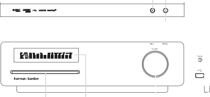
Receiver Front-Panel Controls
Eject Standby
Button Button
TOP
Power
Indicator
FRONT |
|
SIDE |
||||||||
|
|
|
|
|
|
|
|
|
|
|
|
|
|
|
|
|
|
|
|
|
|
|
|
|
|
|
|
|
|
|
|
|
|
|
|
|
|
|
|
|
|
|
|
|
|
|
|
|
|
|
|
|
|
|
|
|
|
|
|
|
|
|
|
|
|
|
|
|
|
|
|
|
|
|
|
|
|
|
|
|
|
|
|
|
|
|
|
|
|
|
|
|
|
|
|
|
|
|
|
|
|
|
|
|
|
|
|
|
|
Disc Slot |
Information |
Volume Control |
Headphone |
USB |
|
Display |
|
Jack |
Port |
Disc Slot: Insert a compatible disc into the slot. The HS 280/HS 210’s disc player will accept five-inch (12cm) and three-inch (8cm) discs.
Information Display: Various messages appear on this display in response to commands. In addition, a variety of indicators will light at various times to show the current source, settings or other aspects of the HS 280/HS 210’s status as described throughout this manual. See Receiver Information Display, on page 7, for details.
Volume Control: Rotate the disc clockwise to raise the volume; rotate counterclockwise to lower the volume. The volume level will appear on the Information Display and on the on-screen menu (if the menu is enabled, see
Preferences – Volume Bar, on page 20).
Eject Button (on top of unit): Press this button to eject a disc from the HS 280/ HS 210’s built-in DVD player. Before pressing this button, make sure that no objects are blocking the disc slot. NOTE: If you do not remove the ejected disc within 20 seconds, it will automatically re-load back into the DVD player for protection.
Standby Button (on top of unit): This button turns the HS 280/HS 210 on for playback or leaves it in the Standby mode for quick turn-on using this button or the remote control.
Power Indicator: This LED (light-emitting diode) surrounds the Standby switch. When the HS 280/HS 210 is plugged into AC power, the LED turns red to indicate that the HS 280/HS 210 is in Standby mode (ready to be turned on). When you turn the HS 280/HS 210 on (by the Standby switch or the remote control), the LED turns white.
Phones (headphones) Jack (on side of unit): Insert the 3.5mm stereo miniconnector from a set of headphones into this jack. NOTE: When a plug is inserted into the Phones jack, the HS 280/HS 210’s speaker outputs automatically mute; the HDMI audio output, coaxial output and line output remain active.
USB 2.0 Port (on side of unit): 
Gently insert a flash drive, card reader, digital camera or other USB device, or a USB Standard-A cable connected to a USB device, to this port.
IMPORTANT: DO NOT connect a PC or other USB host/controller to this port, or you may damage both the HS 280/HS 210 and your other device.
Orient the other device’s plug so it fits all the way into the HS 280/HS 210’s USB connector. You may insert or remove the device at any time — there is no installation or ejection procedure.
The HS 280/HS 210 can play MP3 and Windows Media® Audio WMA audio files that are stored on the device. The HS 280/HS 210 can also display JPEG-format still-image files.
6
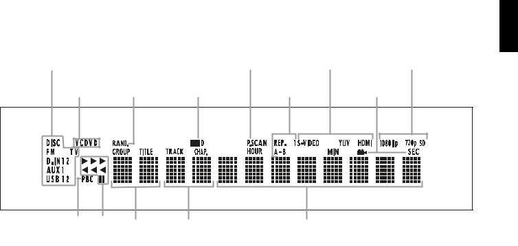
Receiver Information Display
ENGLISH
Source |
|
|
Progressive Scan |
Video Output |
Video Format |
|
|
|
Progressive Scan |
Video Output |
Video Format |
IndicatorsSource |
|
|
Indicators |
||
|
|
Indicator |
Indicators |
||
Indicators |
|
|
Indicator |
Indicators |
Indicators |
|
|
|
|
|
|
Disc Type |
Random Play |
Dolby Digital |
Repeat Play |
Angle |
|
Disc Type |
Random Play |
Dolby Digital |
Repeat Play |
|
Angle |
Indicator |
|
||||
Indicators |
Indicator |
Indicators |
|
Indicator |
|
Indicators |
Indicator |
Indicator |
Indicators |
|
Indicator |
|
|
|
|
|
|
|
|
|
Chapter/Track Number |
|
|
|
|
|
|
|
|
|
|
|
|
VCD |
|
Playback |
Title |
Time |
||||||
|
Chapter/Track Number |
|||||||||
VCD |
|
|
Playback |
Title |
|
Indicators |
Time |
|||
Playback Control |
|
|
Mode |
Indicators |
|
Indicators |
||||
Playback Control |
|
|
Mode |
Indicators |
|
Indicators |
Indicators |
|||
Indicator |
|
|
Indicators |
|
|
|
|
|||
Indicator |
|
Indicators |
|
|
|
|
||||
Source Indicators: Indicate which source is currently playing.
Disc Type Indicators: Indicate the type of disc that is currently playing.
Random Play Indicator: Indicates that the disc player is in the Random Play mode.
Dolby Digital Indicator: Indicates that the soundtrack of the currently-playing disc is Dolby Digital-encoded.
Progressive Scan Indicator: Indicates that the disc player is outputting a progressive-scan video signal.
Repeat Play Indicators: Indicate that the disc player is in one of the Repeat Play modes: Rep. = repeat all; Rep. 1 = repeat track; A–B = A/B repeat.
Video Output Indicators: Indicate which type of video output is currently active.
Angle Indicator: Indicates when alternative viewing angles are available on the currently-playing DVD.
Video Format Indicators: Indicate which video format is currently playing.
VCD Playback Control Indicator: Indicates that the playback-control function is turned on when the HS 280/HS 210 is playing a VCD.
Playback Mode Indicators: Indicate the current disc playback mode:
BIndicates normal playback.
HIndicates that the disc is in the forward fast-search mode. The video display will indicate the selected speed.
1Indicates that the disc is paused. The video display will also indicate that the disc is paused.
GIndicates that the disc is in the reverse fast-search mode. The video display will indicate the selected speed.
Title Indicators: Show the title number of a DVD that is playing.
Chapter/Track Number Indicators: Show the current chapter when a DVD is playing; show the current track number when a CD is playing.
Time Indicators: Show the running time when a DVD is playing; show elapsed time when a CD is playing.
NOTE: The Title, Chapter/Track Number and Time Indicators will also display the radio station name when Radio is the selected input. When a DVD or CD is playing, the indicators will display various text messages about the disc’s status.
7

Receiver Rear-Panel Connections
|
|
|
|
|
|
|
|
|
|
|
|
|
|
|
|
|
|
|
|
|
|
|
Ethernet |
|
|
Remote Control |
|
|
|
|
S-video |
|||||||||||||||||||||||
|
|
|
|
|
|
|
|
|
|
|
|
|
|
|
|
|
|
|
|
|
|
|
|
|
Ethernet |
|
|
Remote Control |
|
|
|
|
|
|
S-Video |
|||||||||||||||||||
|
|
|
|
|
|
|
|
|
|
|
|
|
|
|
|
|
|
|
|
|
|
|
|
|
Port |
|
|
Input/Output |
|
|
|
|
Output |
|||||||||||||||||||||
|
|
|
|
|
|
|
|
|
|
|
|
|
|
|
|
|
|
|
|
|
|
|
|
|
|
|
Port |
|
|
Input/Output |
|
|
|
|
|
|
Output |
|||||||||||||||||
AC Power |
|
|
|
|
|
|
|
|
|
|
|
|
|
|
|
|
|
|
|
|
Coaxial |
|
|
|
|
|
|
|
|
|
|
|
|
|
|
|
|
|
|
|
|
|
|
|
Composite |
|
||||||||
AC Power |
|
|
|
|
|
|
|
|
Speaker |
|
|
|
|
|
Coaxial |
|
|
|
|
|
|
|
|
|
USB |
HDMI |
|
|
|
|
|
|
|
|
|
|
|
Composite |
|
|||||||||||||||
Input |
|
|
|
|
|
|
|
|
|
|
|
|
|
Digital |
|
|
|
|
|
|
|
|
|
|
|
|
|
|
|
|
|
|
|
|
Video |
|
||||||||||||||||||
Input |
|
|
|
|
|
|
|
|
Speaker |
|
|
|
|
|
Digital |
|
|
|
|
|
|
|
|
|
USB |
HDMI |
|
|
|
|
|
|
|
|
|
|
|
Video |
|
|||||||||||||||
|
|
|
|
|
|
|
|
|
|
Outputs |
|
|
|
|
|
Output |
|
|
|
|
|
|
|
|
|
Port |
Output |
|
|
|
|
|
|
|
|
|
|
|
Output |
|
||||||||||||||
|
|
|
|
|
|
|
|
|
|
Outputs |
|
|
|
|
|
Output |
|
|
|
|
|
|
|
|
|
Port |
Output |
|
|
|
|
|
|
|
|
|
|
|
Output |
|
||||||||||||||
|
|
|
|
|
|
|
|
|
|
|
|
|
|
|
|
|
|
|
|
|
|
|
|
|
|
|
|
|
|
|
|
|
|
|
|
|
|
|
|
|
|
|
|
|
|
|
|
|
|
|
|
|
|
|
|
|
|
|
|
|
|
|
|
|
|
|
|
|
|
|
|
|
|
|
|
|
|
|
|
|
|
|
|
|
|
|
|
|
|
|
|
|
|
|
|
|
|
|
|
|
|
|
|
|
|
|
|
|
|
|
|
|
|
|
|
|
|
|
|
|
|
|
|
|
|
|
|
|
|
|
|
|
|
|
|
|
|
|
|
|
|
|
|
|
|
|
|
|
|
|
|
|
|
|
|
|
|
|
|
|
|
|
|
|
|
|
|
|
|
|
|
|
|
|
|
|
|
|
|
|
|
|
|
|
|
|
|
|
|
|
|
|
|
|
|
|
|
|
|
|
|
|
|
|
|
|
|
|
|
|
|
|
|
|
|
|
|
|
|
|
|
|
|
|
|
|
|
|
|
|
|
|
|
|
|
|
|
|
|
|
|
|
|
|
|
|
|
|
|
|
|
|
|
|
|
|
|
|
|
|
|
|
|
|
|
|
|
|
|
|
|
|
|
|
|
|
|
|
|
|
|
|
|
|
|
|
|
|
|
|
|
|
|
|
|
|
|
|
|
|
|
|
|
|
|
|
|
|
|
|
|
|
|
|
|
|
|
|
|
|
|
|
|
|
|
|
|
|
|
|
|
|
|
|
|
|
|
|
|
|
|
|
|
|
|
|
|
|
|
|
|
|
|
|
|
|
|
|
|
|
|
|
|
|
|
|
|
|
|
|
|
|
|
|
|
|
|
|
|
|
|
|
|
|
|
|
|
|
|
|
|
|
|
|
|
|
|
|
|
|
|
|
|
|
|
|
|
|
|
|
|
|
|
|
|
|
|
|
|
|
|
|
|
|
|
|
|
|
|
|
|
|
|
|
|
|
|
|
|
MODEL: HS 2X0SO/230
|
|
|
|
|
|
|
|
|
|
|
|
|
|
|
|
|
|
|
|
|
|
|
|
|
|
|
|
|
|
|
|
|
|
|
|
|
|
|
|
|
|
|
|
|
|
|
|
|
|
|
|
|
|
|
|
|
|
|
|
|
|
|
|
|
|
|
|
|
|
|
|
|
|
|
|
|
|
|
|
|
|
|
|
|
|
|
|
|
|
|
|
|
|
|
|
|
|
|
|
|
|
|
|
|
|
|
|
|
|
|
|
|
|
|
|
|
|
|
|
|
|
|
|
|
|
|
|
|
|
|
|
|
|
|
|
|
|
|
|
|
|
|
|
|
|
|
|
|
|
|
|
|
|
|
|
|
|
|
|
|
|
|
|
|
|
|
|
|
|
|
|
|
|
|
|
|
|
|
|
|
|
|
|
|
|
CoaxialCoaxial |
|
|
SubSub |
|
|
Line |
|
|
|
Line 2 |
|
|
SCART |
|
FM |
|||||||||||||||
Digital |
|
|
|
Trigger |
|
|
Line |
|
|
|
Line 2 |
|
|
|
SCART |
|
FM |
|||||||||||||
|
|
|
OutputsOutputs |
|
InputsInputs |
|
ConnectionConnection |
|
AntennaAntenna |
|||||||||||||||||||||
Digital |
|
|
Trigger |
|
|
|
|
|
|
|
|
|
|
|
|
|
|
|
|
|
|
|
|
|||||||
Inputs |
|
|
Output |
|
|
|
|
|
|
|
|
|
|
|
|
|
|
|
|
|
|
ConnectionConnection |
||||||||
Inputs |
|
|
Output |
|
|
|
|
|
|
|
|
|
|
|
|
|
|
|
|
|
|
|||||||||
|
|
|
|
|
|
|
|
|
|
|
|
|
|
|
|
|
|
|
|
|
|
|
|
|
|
|
|
|||
|
|
|
OpticalOptical |
|
SubwooferSubwoofer |
LineLine 11 |
|
|
|
|
|
|
|
|
|
|
|
|
|
|||||||||||
|
|
|
|
DigitalDigital |
|
OutputOutput |
|
|
|
Inputs |
|
|
|
|
|
|
|
|
|
|
|
|
|
|||||||
|
|
|
|
|
|
|
|
|
|
|
|
|
|
|
|
Inputs |
|
|
|
|
|
|
|
|
|
|
|
|
|
|
InputsInputs
See the Connections section, on page 14, for detailed information about making connections.
AC Power Input: After you have made and confirmed all other connections, plug the supplied AC power cord into this input and into an unswitched AC outlet.
Speaker Outputs: Use the speaker wires supplied with the SAT TS60 speakers to connect the satellite speakers to the proper terminals.
Be sure to connect the positive (+, colored red) connector on the speaker to the positive (+, colored red and white) connector on the HS 280/HS 210, and the negative (– , colored black) connectors on the speakers to the negative (–, colored black) connectors on the HS 280/HS 210. See Connecting the Satellite Speakers, on page 14, for more information about making connections.
Coaxial Digital Inputs: Connect the coaxial digital output of an audio-only source component here. The signal may be a Dolby Digital bitstream or a standard PCM digital audio bitstream.
NOTE: Use only one type of digital connection for each source component.
Optical Digital Inputs: Connect the optical digital output of an audio-only source component here. The signal may be a Dolby Digital bitstream or a standard PCM digital audio bitstream.
NOTE: Use only one type of digital connection for each source component.
Coaxial Digital Output: Connect this output to the coaxial digital input of a digital recording device such as a CD-R or MiniDisc recorder.
Sub Trigger Output: Use the black mini-cable connector of the supplied combination LFE and trigger cable to connect this jack to the HKTS200SUB subwoofer’s External Trigger Input. See Connecting the Subwoofer, on page 15, for more details about making connections.
Whenever the HS 280/HS 210 is turned on, it will send a trigger signal that will turn the subwoofer’s amplifier on. Turning the HS 280/HS 210 off removes the trigger signal, and the subwoofer’s amplifier will turn off. (This change will occur even when the subwoofer’s Power On Mode switch – see page 9 – is in the Auto position.)
Subwoofer Output: Use the LFE (purple) connector of the supplied combination LFE and trigger cable to connect this jack to the HKTS200SUB subwoofer’s Line-Level In LFE jack. See Connecting the Subwoofer, on page 15, for more details about making connections.
Ethernet Port: Connect this port to your local area network (LAN) using a CAT 5 RJ45 network cable. See Connecting to a Local Area Network (LAN), on page 17, for details.
Line Outputs: Use the Line Outputs to connect to an audio-only recorder, such as a CD-R recorder or tape deck.
USB 2.0 Port: Gently insert a flash drive, card reader, digital camera or other USB device, or a USB Standard-A cable connected to a USB device, to this port.
IMPORTANT: DO NOT connect a PC or other USB host/controller to this port, or you may damage both the HS 280/HS 210 and the other device. Orient the device’s plug so it fits all the way into the HS 280/HS 210’s USB connector. You may insert or remove the device at any time – there is no installation or ejection procedure.
The HS 280/HS 210 can display JPEG-format still-image files stored on the device and can also play MP3 and Windows Media® Audio (WMA) files and MPEG4 and AVI video files that are stored on the device.
Line 1 Input/Line 2 Inputs: Use these inputs to connect to an audio-only source component (such as a tape deck). Do not connect a turntable to these jacks without a phono preamp.
HDMI Output (HDMI version 1.2): If your video display is HDMI-capable, connect it to the HS 280/HS 210’s HDMI output for improved video performance. Since the HDMI cable transmits both video and audio to the video display, we recommend that you disable your display’s HDMI audio function to take full advantage of the HS 280/ HS 210 system’s superior audio performance (See page 19).
IMPORTANT: The HS 280/HS 210 is in compliance with HDCP (High-Definition Copy Protection). A video display must also be HDCP-compliant to be used with the HS 280/ HS 210’s HDMI output. For best results, we do not recommend HDMI connections in excess of ten feet without a repeater. If your video display has a DVI input, you may use an optional HDMI-to-DVI cable or adapter for the video connection to the display. (The DVI connection is video-only.)
8

Remote Control Input/Output: If the HS 280/HS 210’s front-panel IR sensor is blocked, such as when it is placed inside of a cabinet, connect an external IR receiver (such as the Harman Kardon HE 1000 – not included) to the Remote Control In connector. You can then place the external IR receiver in a location where it can receive the signals from the HS 280/HS 210 remote control.
You can connect the HS 280/HS 210’s Remote Control Out connector to the remote IR input of a compatible device, allowing it to be controlled through the HS 280/HS 210 (and through an external IR receiver, if connected). You can even connect several such compatible devices together in “daisy-chain” fashion.
SCART Connection: Connect it to a compatible TV or set-top box using the included SCART cable. The SCART cable carries composite (CVBS) video or S-Video from the HS 280/HS 210 to a TV or set-top box (as well as a control signal for automatically controlling picture aspect ratio and other parameters). It also carries stereo audio from the TV or set-top box back to the HS 280/HS 210.
Composite-Video Output: Connect it to the composite-video input of a TV or video projector.
S-Video Output: Connect it to the S-Video input of a TV or video projector.
FM Antenna Connection: Connect the supplied FM antenna to this terminal.
Subwoofer Controls and Connections
SubwooferSubwoofer
Level Control
Level Control
Bass BoostBass Boost
Switch Switch
Phase SwitchPhase Switch
Power OnPower On
Mode Switch
Mode Switch
External Trigger |
|
External Trigger |
|
Input Connector |
|
Input Connector |
|
Line-Level In |
|
Line-Level In |
|
LFE Connector |
|
LFE Connector |
3/ |
Line-Level In |
|
Line-Level In |
|
L/R Connectors |
|
L/R Connectors |
|
Power Switch |
|
Power Switch |
|
AC Power Cord |
|
AC Power Cord |
|
Subwoofer Level Control: Use this control to adjust the HKTS200SUB subwoofer’s volume. Turn clockwise to increase the volume; turn counterclockwise to decrease the volume.
Bass Boost Switch: Set this switch to On to enhance the subwoofer’s low-frequency performance. Set this switch to Off for normal low-frequency performance.
Phase Switch: This switch determines whether the subwoofer driver’s piston-like action moves in and out in phase with the satellite speakers. If the subwoofer were to play out of phase with the satellite speakers, the sound waves from the satellite speakers could cancel out the sound waves from the subwoofer, reducing bass performance and sonic impact. This phenomenon depends in part on the relative placement of all the speakers in the room.
Although in most cases the Phase Switch should be left in the Normal position, there is no absolutely correct setting for it. When the subwoofer is properly in phase with the satellite speakers, the sound will be clearer and have maximum impact. It will make percussive sounds like drums, piano and plucked strings sound more lifelike. The best way to set the Phase Switch is to listen to music that you know well and set the switch in the position that gives drums and other percussive sounds maximum impact.
Power On Mode Switch: When this switch is set in the Auto position and when the Power switch is set to On, the HKTS200SUB will automatically turn itself On whenever it receives an audio signal. It will enter the standby mode if it receives no audio signal for 20 minutes. When the Power On Mode switch is set in the On position, the subwoofer will remain on whether or not it is receiving an audio signal.
An LED on the subwoofer’s top panel indicates whether the subwoofer is in the on or standby mode:
•• When the LED is illuminated white, the subwoofer is turned on.
•• When the LED is not illuminated, the subwoofer is in standby mode.
When the Power switch is set to Off, the LED will not be illuminated, no matter what setting the Power On Mode switch is in.
External Trigger Input Connector: Use the mini-plug of the supplied combination LFE and trigger cable to connect the External Trigger Input to the trigger output
of another compatible component. Whenever the subwoofer detects a trigger signal between 3V and 30V (AC or DC), the subwoofer’s amplifier will turn on. The subwoofer’s amplifier will turn off after the trigger signal ceases. (This change will occur even when the Power On Mode switch is in the Auto position.)
Line-Level In LFE Connector: Use the LFE (purple) connector of the supplied combination LFE and trigger cable to connect the Line-Level In LFE connector to the dedicated subwoofer output of a receiver or preamp/processor. This input bypasses the subwoofer’s internal crossover circuitry, so use it only with a subwoofer output that is low-pass filtered. (Check the receiver or preamp/processor’s documentation to confirm that its subwoofer output is low-pass filtered.) If your receiver or preamp/ processor does not have a dedicated subwoofer output that is low-pass filtered, use the subwoofer’s Line-Level In L/R connectors instead.
Line-Level In L/R Connectors: Use these connectors if your receiver or preamp/ processor does not have digital surround-sound decoding or a low-pass-filtered subwoofer output.
•• If your receiver or preamp/processor has a separate subwoofer output, use the LFE (purple) connector of the supplied combination LFE and trigger cable to connect the receiver or preamp/processor’s subwoofer output to either one of the subwoofer’s Line-Level In L/R connectors.
•• If your receiver or preamp/processor does not have a separate subwoofer output, use two Y-adapters (not supplied). Connect one adapter’s single end to the unit’s preamp output for that channel. Connect one of this adapter’s dual ends to the main amp input for that channel, and connect the adapter’s other dual end to one of the subwoofer’s Line-Level In L/R Connectors. Repeat this process with the other Y-adapter, the preamp channel, the main amp input and the subwoofer’s other Line-Level In L/R connector.
Power Switch: Set this switch in the On position to turn the subwoofer on. The subwoofer will then either be on or in Standby mode, depending on the setting of the subwoofer’s Power On Mode switch.
AC Power Cord: After you have made and verified all subwoofer and speaker connections described in this manual, plug the Power Cord into an active, unswitched electrical outlet (that is, an outlet not connected to a light switch) for proper operation of the subwoofer. DO NOT plug this cord into the accessory outlets found in some audio components.
ENGLISH
9
 Loading...