


2.0 Processor/Tuner
Owner’s Manual

Owner’s Manual
Signature 2.0 Processor/Tuner
Table of Contents
Introduction . . . . . . . . . . . . . . . . . . . . . . . . . . . . . . . . . . . . . . . . . 1
Safety Information . . . . . . . . . . . . . . . . . . . . . . . . . . . . . . . . . . 2–3
Unpacking and Installation . . . . . . . . . . . . . . . . . . . . . . . . . . . . . . 3
Quick Start Instructions . . . . . . . . . . . . . . . . . . . . . . . . . . . . . . 5–7
Front Panel Controls . . . . . . . . . . . . . . . . . . . . . . . . . . . . . . . . . 8–9
Rear Panel Connections . . . . . . . . . . . . . . . . . . . . . . . . . . . . 10–11
Remote Control Operation . . . . . . . . . . . . . . . . . . . . . . . . . . 12–15
Remote Control Programming . . . . . . . . . . . . . . . . . . . . . . . 16–18
System Installation . . . . . . . . . . . . . . . . . . . . . . . . . . . . . . . . 19–21
System Configuration . . . . . . . . . . . . . . . . . . . . . . . . . . . . . . 22–26
Source Configuration . . . . . . . . . . . . . . . . . . . . . . . . . . . . . . 27–31
Advanced Setup . . . . . . . . . . . . . . . . . . . . . . . . . . . . . . . . . . 32–34
Operation . . . . . . . . . . . . . . . . . . . . . . . . . . . . . . . . . . . . . . . 35–51
Troubleshooting Guide . . . . . . . . . . . . . . . . . . . . . . . . . . . . . 52–54
Appendix A. . . . . . . . . . . . . . . . . . . . . . . . . . . . . . . . . . . . . . . . . 55
Appendix B . . . . . . . . . . . . . . . . . . . . . . . . . . . . . . . . . . . . . . . . . 56
Appendix C. . . . . . . . . . . . . . . . . . . . . . . . . . . . . . . . . . . . . . 57–61
Technical Specifications . . . . . . . . . . . . . . . . . . . . . . . . . . . . 62–63
Figure Index . . . . . . . . . . . . . . . . . . . . . . . . . . . . . . . . . . . . . . . . 64
Subject Index . . . . . . . . . . . . . . . . . . . . . . . . . . . . . . . . . . . . . . . 65
80 Crossways Park West
Woodbury, NY 11797
www.harmankardon.com
©1997 Harman Kardon, Incorporated

Staple or clip your original invoice here. ¤
Signature 2.0
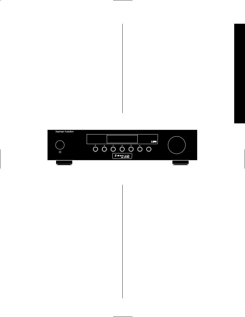
Congratulations! With the purchase of a Harman Kardon Signature Series product you are about to begin many years of listening enjoyment. The Model 2.0 Processor/Tuner has been designed to provide all the excitement and detail of motion picture soundtracks and reproduce every subtle nuance of your favorite musical selection. On-board Dolby* Digital decoding enables the 2.0 to deliver six channels of fully discrete sound from today’s DVD releases and tomorrow’s HDTV broadcasts, while a wide selection of matrix decoding modes delivers full compatibility with conventional Dolby Surround stereo and mono programs. The 2.0 is also ready to accept future surround systems through the use of sixchannel direct inputs that accommodate optional outboard decoders for future surround systems.
the meaning of the on-screen and front panel display messages will enable you to take advantage of all the power the Signature 2.0 is able to deliver.
Harman Kardon has been a part of the audio world
since it invented the first high-fidelity receiver over fortyfive years ago. With the combination of state-of-the-art circuitry and time honored design philosophies, the Signature 2.0 is one of the most innovative products ever offered by Harman Kardon. Should you have any questions about this product, its operation or installation that are not answered in this manual please contact your retailer or custom installer. They are your best source for
product information. You may also contact Harman Kardon via the World Wide Web at www.harmankardon.com
2.0
|
DVD |
Vol |
|
Standby |
Dolby Digital |
|
|
|
10 |
|
|
Source |
Surround |
Tune |
Mute |
On/Off
Introduction
While complex digital circuits are hard at work within the 2.0, a simple on-screen menu system and learning remote control make the unit easy to install and operate.
In addition to selecting from a variety of audio/video sources, the Signature 2.0 is equipped with the latest in tuner technology, including the RDS data system that automatically identifies FM stations transmitting special data and provides information they transmit
about the station’s programming. The RDS system even lets you automatically search for a station with a specific program type from the participating stations in your reception area.
To obtain maximum benefit from the Signature 2.0’s many features we urge you to take a few minutes to read through this manual. That will ensure that connections to playback sources, power amplifiers and other external devices are made properly. In addition, a few minutes spent learning the functions for the various controls and
The following are among the 2.0’s many features:
■On-Board Dolby Digital Decoding
■Multiple Coax and Optical Digital Inputs
■Composite and S-Video Switching
■Easy-To-Use On-Screen Menu Control System
■FM Stereo/AM Tuner With RDS Data System and 30 Presets
■Learning Remote Control Pre-Programmed With Harman Kardon and RC-5 Control Codes
■Trigger Output For Automatic Control of Signature Series Power Amplifiers
■RS-232 Control Port For Connection To External Automation Systems
■Six-Channel Direct Inputs For Use With External Audio Adapters or Decoders.
1
Safety Information
Signature 2.0
Important Safety Information
Verify Line Voltage Before Use
This Signature 2.0 has been designed for use with 120-volt AC current. Connection to a line voltage other than that for which it is intended can create a safety and fire hazard, and may damage the unit.
If you have any questions about the voltage requirements for your specific model, or about the line voltage in your area, contact your selling dealer before plugging the unit into a wall outlet.
Do Not Use Extension Cords
To avoid safety hazards, use only the power cord attached to your unit. We do not recommend that extension cords be used with this product. As with all electrical devices, do not run power cords under rugs or carpets or place heavy objects on them. Damaged
power cords should be replaced immediately with cords meeting factory specifications.
Handle the AC Power Cord Gently
When disconnecting the power cord from an AC outlet, always pull the plug, never pull the cord. If you do not intend to use the unit for any considerable length of time, disconnect the plug from the AC outlet.
Do Not Open The Cabinet
There are no user-serviceable components inside this product. Opening the cabinet may present a shock hazard, and any modification to the product will void your guarantee. If water or any metal object such as a paper clip, wire or a staple accidentally falls inside the unit, disconnect it from the AC power source
immediately, and consult an authorized service station.
CAUTION
RISK OF ELECTRIC SHOCK
DO NOT OPEN
CAUTION: TO REDUCE THE RISK OF ELECTRIC SHOCK, DO NOT REMOVE COVER (OR BACK). NO USER-SERVICEABLE PARTS INSIDE. REFER SERVICING TO QUALIFIED SERVICE PERSONNEL.
The lightning flash with arrowhead |
The exclamation point within an |
symbol, within an equilateral triangle, is |
equilateral triangle is intended to |
intended to alert the user to the |
alert the user to the presence of |
presence of uninsulated “dangerous voltage” |
important operating and maintenance |
within the product’s enclosure that may be of |
(servicing) instructions in the literature |
sufficient magnitude to constitute a risk of |
accompanying the appliance. |
electric shock to persons. |
|
WARNING: TO REDUCE THE RISK OF FIRE OR ELECTRIC SHOCK, DO NOT EXPOSE THIS APPLIANCE TO RAIN OR MOISTURE.
CAUTION: TO PREVENT ELECTRIC SHOCK, MATCH WIDE
BLADE OF PLUG TO WIDE SLOT, FULLY INSERT.
ATTENTION: POUR EVITER LES CHOCS ELECTRIQUES, INRODUIRE LA LAME LA PLUS LARGE DE LA FICHE DANS LA BORNE CORRESPONDANTE DE LA PRISE ET POUSSER JUSQU'AU FOND.
CATV or Antenna Grounding
If an outside antenna or cable system is connected to this product, be certain that it is grounded so as to provide some protection against voltage surges and static charges. Section 810 of the National Electrical Code, ANSI/NFPA No. 70-1984, provides information with respect to proper grounding of the mast and supporting structure, grounding of the lead-in wire to an antenna discharge unit, size of grounding conductors, location
of antenna discharge unit, connection to grounding electrodes and requirements of the grounding electrode.
NOTE TO CATV SYSTEM INSTALLER:
This reminder is provided to call the CATV (Cable TV) system installer’s attention to article 820-40 of the NEC that provides guidelines for proper grounding and, in particular, specifies that the cable ground shall be connected to the grounding system of the building, as close to the point of cable entry as possible.
Installation Location
■To assure proper operation, and to avoid the potential for safety hazards, place the unit on a firm and level surface. When placing the unit on a shelf, be certain that the shelf and any mounting hardware can support the weight of the product.
■Make certain that proper space is provided both above and below the unit for ventilation. If this product will be installed in a cabinet or other enclosed area, make certain that there is sufficient air movement within the cabinet. Under some circumstances a fan may
be required.
■Do not place the unit directly on a carpeted surface.
■Avoid installation in extremely hot or cold locations, or an area that is exposed to direct sunlight or heating equipment.
■Avoid moist or humid locations.
■Do not obstruct the ventilation slots on the top of the unit, or place objects directly over them.
2

Signature 2.0
Cleaning
When the unit gets dirty, wipe it with a clean, soft dry cloth. If necessary, wipe it with a soft cloth dampened with mild soapy water, then a fresh cloth with clean water. Wipe dry immediately with a dry cloth. NEVER use benzene, aerosol cleaners, thinner, alcohol or any other volatile cleaning agent. Do not use abrasive cleaners, as they may damage the finish of metal parts. Avoid spraying insecticide near the unit.
Moving The Unit
Before moving the unit, be certain to disconnect any interconnection cords with other components, and make certain that you disconnect the unit from the AC outlet.
Important information for the user
NOTE: This equipment has been tested and found to comply with the limits for a Class B digital device, pursuant to Part 15 of the FCC Rules. The limits are designed to provide reasonable protection against harmful interference in a residential installation. This equipment generates, uses and can radiate radio frequency energy and, if not installed and used in accordance with the instructions, may cause harmful interference to radio communication. However, there is no guarantee that harmful interference will not occur in a particular installation. If this equipment does cause harmful interference to radio or television reception, which can be determined by turning the equipment off and on, the user is encouraged to try to correct the interference by one or more of the following measures:
■Reorient or relocate the receiving antenna.
■Increase the separation between the equipment and receiver.
■Connect the equipment into an outlet on a circuit different from that to which the receiver is connected.
■Consult the dealer or an experienced radio/TV technician for help.
This device complies with Part 15 of the FCC Rules. Operation is subject to the following two conditions:
(1) this device may not cause harmful interference, and (2) this device must accept interference received, including interference that may cause undesired operation.
NOTE: Changes or modifications may cause this unit to fail to comply with Part 15 of the FCC Rules and may void the user’s authority to operate the equipment.
Unpacking and Installation
The carton and shipping materials used to protect your new 2.0 during shipment were specially designed to cushion it from shock and vibration. We suggest that you save the carton and packing materials for use in shipping if you move or should the unit ever need repair.
To minimize the size of the carton in storage, you may wish to flatten it. This is done by carefully slitting the tape seams on the bottom and collapsing the carton down to a more two-dimensional appearance. Other cardboard inserts may be stored in the same manner. Packing materials that cannot be collapsed should be saved along with the carton in a plastic bag.
If you do not wish to save the packaging materials, please note that the carton and other sections of the shipping protection are recyclable. Please respect the environment and discard those materials at a local recycling center.
Typographic Conventions
In order to help you use this manual with diagrams of the remote control, front panel controls, rear panel connections and on-screen menus, certain conventions have been used.
Example – (bold type) indicates a specific remote control or front panel button, or rear panel connection jack
Example – (OCR type) indicates a message that is visible through the on-screen menu system or on the front panel information display
1– (number in a square) indicates a specific front panel control
a– (number in an oval) indicates a button or indicator on the remote
¡ – (number in a circle) indicates a rear panel connection
Information Safety
3

Signature 2.0
4

Signature 2.0
Quick Start Instructions
The Signature 2.0 is a powerful, yet easy-to-use product. In order to obtain the maximum benefit from its many features and options, it is strongly recommended that you take the time to carefully read the instructions in this manual. It contains a wealth of information that will help you to safely and properly install and use this product.
We realize, however, that you may be anxious to use your system, so the following steps are provided to outline the minimum instructions needed to get everything connected and “on the air.” Please follow the directions carefully in order to avoid damage to the Signature 2.0 or other components in your system.
If you choose to take advantage of these Quick Start instructions we nevertheless urge you to read through the Owner’s Manual at a later time so that
your system may be adjusted for optimal performance. That small investment of your time will yield major dividends in the long term in the form of hours of greater listening pleasure.
Equipment Required for Quick Start Installation:
Signature 2.0 Processor/Tuner and Supplied Accessories
Front Left, Center and Right Speakers
Left and Right Surround Speakers
Five Channels of Audio Power Amplification
Powered Subwoofer or Passive Subwoofer and External Amplifier
Source Equipment (e.g., VCR, DVD, CD, Satellite Receiver, etc.)
Interconnect and Speaker Cables
NOTE: If your equipment does not match the list above you should NOT use the Quick Start instructions,
as additional settings must be made beyond those shown on the next two pages. For complete installation instructions, see page 19.
Instructions Start Quick
5
Quick Start Instructions
Signature 2.0
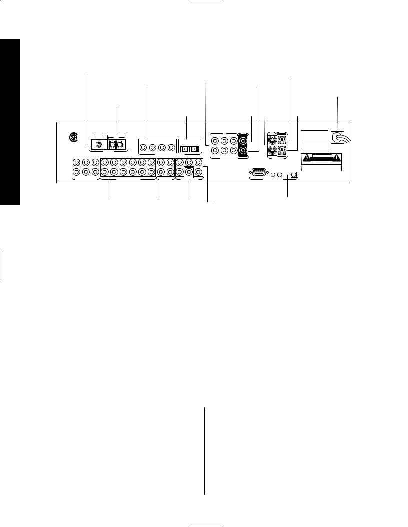
Quick Start Connection and Setup
Connect 75-ohm |
Connect to coaxial |
Connect to output |
Connect to |
FM antenna here |
digital audio output |
of composite |
composite |
|
of A/V sources, DVD, |
video sources |
video input |
|
HDTV, CD, etc. |
|
of VCRs |
Connect AM loop |
Connect to optical |
Connect to |
Connect to |
antenna here |
digital audio output |
composite |
S-Video |
|
of A/V sources, DVD, |
video input of |
output |
|
HDTV, CD, etc. |
main monitor |
sources |
Connect to S-Video input of main monitor
Connect AC Power to non-switched wall outlet
Connect to S-Video input of VCRs
|
|
|
|
|
|
|
|
|
|
|
|
|
|
IN |
|
|
IN |
|
|
MODEL NO.: SIGNATURE SERIES 2.0 |
|
|
|
|
|
|
|
|
|
|
|
|
|
1 |
|
|
1 |
MAIN |
|
HARMAN KARDON |
|
|
|
FM |
|
|
AM |
|
|
|
|
|
|
|
2 |
3 |
MAIN |
|
NORTHRIDGE |
|||
® |
|
|
|
|
|
|
|
|
|
|
|
|
|
|||||||
|
|
|
|
|
|
|
|
|
|
|
|
|
|
|
|
|
CALIFORNIA, USA |
|||
|
|
|
|
|
|
|
|
|
|
|
|
|
|
|
|
|
|
|
|
MADE IN USA |
NRTL /C |
|
|
|
|
|
|
1 |
2 |
3 |
4 |
|
5 |
6 |
|
|
|
|
|
|
115V ~ 60Hz |
|
|
|
|
|
|
|
|
|
|
|
|
|
|
|
|
|
|
|
||
LR110480 |
|
|
|
|
|
|
|
|
|
|
|
|
|
|
|
|
|
|
|
75 WATTS |
CSA E65 |
|
|
ANTENNA |
|
|
|
|
|
|
|
|
|
|
|
|
|
|
|
|
SERIAL NUMBER |
|
|
|
|
|
|
|
|
|
|
|
|
|
|
|
|
|
|
|
|
|
|
|
|
|
|
|
|
|
|
DIGITAL AUDIO DATA INPUTS |
|
4 |
5 |
6 |
REC |
2 |
REC |
|
CAUTION |
||
FRONT |
CENTER |
SURR |
1 |
2 |
3 |
4 |
5 |
6 |
|
|
FRONT |
CENTER |
|
|||||||
|
|
SURR |
COMPOSITE VIDEO |
|
S – VIDEO |
|
RISK OF ELECTRIC SHOCK |
|||||||||||||
L |
|
|
|
|
|
|
|
|
|
|
|
|
L |
|
|
|
|
|
|
DO NOT OPEN |
|
|
|
|
|
|
|
|
|
|
|
|
|
|
|
|
|
|
AVIS: RISQUE DE CHOC ELECTRIQUE - NE PAS OUVRIR |
||
|
|
|
|
|
|
|
|
|
|
|
|
|
|
|
|
|
|
|
|
|
|
|
|
|
|
|
|
|
|
|
|
|
|
|
|
|
|
RS-232 |
|
|
WARNING: TO REDUCE THE RISK OF FIRE |
|
|
|
|
|
|
|
|
|
|
|
|
|
|
|
|
|
IR |
IR |
TRIGGER |
OR ELECTRIC SHOCK DO NOT EXPOSE THIS |
R |
|
|
|
|
|
|
|
|
|
|
|
|
R |
|
|
|
EQUIPMENT TO RAIN OR MOISTURE. |
|||
|
|
|
|
|
|
|
|
|
|
|
|
|
|
|
IN |
OUT |
OUTPUT |
|||
|
|
|
|
|
|
|
|
|
|
|
|
|
|
|
|
|
|
|||
|
|
|
|
|
|
|
|
|
|
|
|
|
|
|
|
|
|
|
|
Manufactured under license from Dolby Laboratories Licensing |
|
SUB |
|
|
|
|
|
|
|
|
|
|
SUB |
|
|
|
|
|
|
|
Corporation. "Dolby", "AC-3", "Pro Logic" and the Double-D symbol |
|
|
|
|
|
|
|
|
|
|
|
|
|
|
|
|
|
|
are trademarks of Dolby Laboratories Licensing Corporation. |
||
6-CH DIRECT INPUTS |
|
|
ANALOG AUDIO INPUTS |
|
|
REC OUTPUTS |
AUDIO OUTPUTS |
|
|
|
EXTERNAL CONTROLS |
|
Copyright 1992 Dolby Laboratories, Inc. All rights reserved. |
|||||||
Connect to analog audio |
Connect to audio |
Connect to |
Connect to |
Connect to "Trigger |
output of A/V sources, |
input of VCR or |
a powered |
inputs of audio |
In" jack on Signature |
CD, tuner, etc. |
audio recorders |
subwoofer |
power amplifiers |
Series or other compatible |
|
|
or subwoofer |
|
power amplifier |
|
|
amplifier |
|
|
1.Before proceeding, make certain that all equipment, including the 2.0, is unplugged from AC power. This will prevent any damage due to the unintended activation of automatic turn-on circuits.
2.Using high-quality audio interconnect cables, connect the audio and video output (including the “Play/Out” outputs of VCR or cassette decks) on your source equipment according to the following chart. If your equipment list requires different connections, you will need to make some setup changes as detailed on page 28 of this manual.
Source Equipment |
Video Input Connections |
Audio Input Connections |
Cable Box, TV or Satellite |
Composite Video 2 |
Analog Audio Input 2 |
VCR |
Composite Video 1 |
Analog Audio Input 1 |
DVD |
S-Video 1 |
Digital Audio Input 1 |
Laser Disc Player |
S-Video 2 |
Digital Audio Input 2 |
|
|
|
CD Player with Coax Output |
N/A |
Digital Audio Input 3 |
|
|
|
Tape Deck |
N/A |
Analog Audio Input 5 |
Auxiliary Device |
Composite Video 1 |
Analog Audio Input 4 |
|
|
|
3. Connect the video “Record Inputs” of your VCR to the
Composite or S-Video “Rec” Outputs .
4. Connect the audio “Record Inputs” of your VCR and/or audio tape recorder to the “Rec” Outputs on the rear of the 2.0. There is no problem in sending the feed to both recorders and two recordings may be made at one time from the same source.
5.Connect the Composite or S-Video “Main” Outputs to the matching Composite or S-Video input on your TV monitor or projector.
6.Connect the AM and FM antennae supplied with the 2.0 to the proper antenna connections on the rear panel.
6

Signature 2.0
7.If a Signature Series audio power amplifier, or other compatible amplifier, is being used, connect the power trigger cable supplied with the 2.0 to the Trigger Output on the 2.0 and the amplifier’s compatible Trigger Input.
8.Connect the Audio Outputs of the 2.0 to the inputs of your five-channel power amplifier. Be certain that channels are properly matched (e.g., connect left to left, right to right, etc.) Connect the Sub Output to the mono “line level” input of a powered subwoofer, or to the audio input of the amplifier channel feeding a passive subwoofer. Connect the audio amplifier to the speakers, carefully following the instructions provided with the speaker and amplifier, and ensure that polarity is matched between the speaker and amplifier when connections are made.
9.Install the batteries in the remote control, being careful to observe the (+) and (–) polarity indicators on the remote and the batteries.
10.Connect all devices, including the 2.0, to AC
power and turn everything on EXCEPT for the 2.0 and any audio amplifier not connected to the 2.0’s triggered output.
11. Press the Master Power Switch on the 2.0 in until it latches and is flush with the front panel. An amber standby LED will light, and the front panel Information Display will come on briefly to display the software version installed in your unit and then a Power Off Standby message will show briefly. The unit will then go into the Standby mode.
•To use the On-Screen Menu System, make certain that your TV or other video display device is turned on and switch to the proper video input at this point.
12. To turn the 2.0 on, press either the front panel Standby button, the Main On button on the remote, or any of the source buttons on the remote (e.g., TV, Vid 1, Tuner, etc.). The front panel Information Display will illuminate, the amber standby LED will
go out and be replaced by blue illumination behind the word “Signature” on the front panel. A message will briefly appear in the on-screen display with the source, surround mode and volume.
•If you are using a Signature Series amplifier or another compatible amplifier connected to the Trigger Output jack, it will receive a turn-on signal as soon as the 2.0 is turned on. Note that with most amplifiers there will be a short, intentional delay between the turn-on signal and when the amplifier sends signals to the speakers. This is a normal function designed to prevent damage to your speakers.
•If you are using an amplifier not controlled by the 2.0’s Trigger Output, turn it on at least 10 seconds AFTER the 2.0 is turned on.
13. You may change the input source by pressing the front panel Source buttons or any of the Source buttons on the remote. Volume for the 2.0 may be raised or lowered using the front panel Volume knob or the Volume Up/Down buttons on the remote. Finally, to change the surround mode, press Surround buttons or the Mono +, Music, Movies or Stereo buttons on the remote.
At this point you are “on the air!” Sit back and enjoy the best in home entertainment.
Of course, this is only the tip of the iceberg. Although you have successfully completed a minimal installation we strongly recommend that you take time to read this manual thoroughly. It will show you how to use the many features, modes and controls that are a vital part of the Signature 2.0. Correct setup and installation is important to optimizing the sound quality of your new controller, and will also make it easier to operate. A few minutes spent reading the manual and making certain that your new 2.0 is set up to meet the individual characteristics of your system and listening room will enable the 2.0 to deliver all the performance it is
capable of.
Instructions Start Quick
7
Front Panel Controls
Signature 2.0
Front Panel Controls
! |
) |
|
9 |
2.0 |
|
|
|
|
DVD |
Vol |
|
Standby |
Dolby Digital |
|
|
|
10 |
|
|
Source |
Surround |
Tune |
Mute |
|
On/Off |
|
|
|
|
1 |
2 |
3 |
4 |
5 6 7 |
8 |
1 Master Power Switch |
5 Standby LED |
9 Volume Control |
2 Standby Switch |
6 Power Indicator |
)Information Display |
3 Source Selectors |
7 Tune Buttons |
!Remote Sensor Window |
4 Surround Selectors |
8 Mute Button |
|
1 Master Power Switch: This is the main power control for the 2.0. To turn the unit on, press this switch in until it latches and is flush with the front panel. To turn the unit off press in briefly, and the switch will unlatch and pop out. Once this switch is in the “ON” position you may leave it there and use the remote control or standby switch to turn the 2.0 on or off.
NOTE: Even when the Master Power Switch is in the “OFF” position, the 2.0 is still connected to the AC power source.
2 Standby Switch: Press this switch to turn the unit on from the Standby mode. Press it again to return to the Standby mode. Note that in order for this switch to operate the 2.0, the Master Power Switch 1must be in the “ON” position, as indicated by the amber
Standby LED 5.
3 Source Selectors: Press these buttons to change the input source selection. Use them to scroll through the list of sources you watch and listen to.
4 Surround Selectors: Press these buttons to change the surround mode in use. Note that the list of modes available is different for digital or analog audio sources.
5 Standby LED: When this indicator lights in an amber color, the 2.0 is in the Standby mode, and it is ready to be turned on or off when the Standby Switch 2, or the remote Main On/Off aare pressed. When the Standby LED is out, but the Power Indicator 6is illuminated in blue, the unit is on. When both of these indicators are dark, the 2.0 is fully off, indicating that the Master Power Switch 1 is in the “OFF” position or the 2.0 is not plugged into a live AC power source.
6 Power Indicator: This indicator is illuminated in blue when the 2.0 is in full operation. If it is not lit, and the Standby LED 5is amber, the unit is in the Standby mode. When neither indicator is lit, the
2.0 is off, or the unit is not connected to a live AC power source.
8

Signature 2.0
7 Tune Buttons: Press these buttons when the tuner is the input source to select the station being listened to from the frequencies previously entered into the preset memories.
8 Mute Button: Press this button to temporarily silence the audio output. Press the button again, or change the volume level to return to normal operation. Note that when the Mute function is activated, the feed to any recorders connected to the Record Outputs £ will remain uninterrupted. When Mute is engaged a reminder message will appear in the on-screen display (see figure OSD-15 on page 36) and the word Mute will replace the volume level in the Information Display )(see figure FPD-9 on page 36).
9 Volume Control: Turn this knob to the right or left to raise or lower the volume. This is an electronic volume control, so unlike the conventional volume controls you may be used to, it does not have a start or end point to its rotation. Volume indications are provided
in both the front panel Information Display ) and the on-screen control system (see figure OSD-13 on page 36) to provide information about the relative volume setting.
) Information Display: This two-line display is your window into the status and operation of the 2.0. In normal operation it displays the current input source
and surround mode at the left side of the display, and the volume level on the right side. When the tuner is in use the top line of the display will show the preset number and frequency of the station being listened to. Additional messages will be displayed depending on which input or mode is in use, including RDS data from the FM tuner, and abbreviated versions of the on-screen menus used during installation, setup and configuration.
! Remote Sensor Window: This area contains the sensor that receives commands from the Signature 2.0’s infrared remote control. Make certain that it is not blocked by cabinets, smoked glass or doors or other objects that may interfere with the line of sight from the remote.
Controls Panel Front
9
Rear Panel Connections
Signature 2.0
Rear Panel Connections
IMPORTANT NOTE: Never make or remove any connections to the Signature 2.0 with the Master Power Switch in the “ON” position. It is also a good practice to make certain that the power amplifiers connected to the 2.0 are also turned off when making or removing any connections. This eliminates the risk of possible damage to your speakers or other system components.
When making connections to the Signature 2.0 make certain that the plugs are firmly seated into the jacks. This prevents intermittent connections which may interfere with performance.
a · |
° ‡ fl |
fi›‹ ¤⁄ ‚ |
This device complies with part 15 of the FCC Rules. Operation is subject to the following two conditions:
(1) This device may not cause harmful interference, and (2) this device must accept any interference received, including interference that may cause undesired operation.
® |
FM |
AM |
1 |
2 |
3 |
4 |
5 |
6 |
NRTL /C
LR110480
CSA E65
ANTENNA
|
|
|
|
|
|
|
|
DIGITAL AUDIO DATA INPUTS |
|
|
FRONT CENTER |
SURR |
1 |
2 |
3 |
4 |
5 |
6 |
|
FRONT CENTER |
SURR |
L |
|
|
|
|
|
|
|
|
|
L |
R |
|
|
|
|
|
|
|
|
|
R |
SUB |
|
|
|
|
|
|
|
|
SUB |
|
6-CH DIRECT INPUTS |
|
|
ANALOG AUDIO INPUTS |
|
|
REC OUTPUTS |
AUDIO OUTPUTS |
|||
1 |
IN |
|
OUT |
2 |
3 |
MAIN |
|
4 |
5 |
6 |
REC |
COMPOSITE VIDEO
Double Insulated – When servicing use only identical replacement parts.
IN |
OUT |
|
1 |
MAIN |
|
2 |
REC |
|
S – VIDEO |
|
|
RS-232 |
|
|
IR |
IR |
TRIGGER |
IN |
OUT |
OUTPUT |
EXTERNAL CONTROLS
MODEL NO.: SIGNATURE SERIES 2.0
HARMAN KARDON
NORTHRIDGE
CALIFORNIA, USA
MADE IN USA
115V ~ 60Hz
75 WATTS
SERIAL NUMBER
CAUTION
RISK OF ELECTRIC SHOCK
DO NOT OPEN
AVIS: RISQUE DE CHOC ELECTRIQUE - NE PAS OUVRIR
WARNING: TO REDUCE THE RISK OF FIRE OR ELECTRIC SHOCK DO NOT EXPOSE THIS EQUIPMENT TO RAIN OR MOISTURE.
Manufactured under license from Dolby Laboratories Licensing Corporation. "Dolby", "AC-3", "Pro Logic" and the Double-D symbol are trademarks of Dolby Laboratories Licensing Corporation. Copyright 1992 Dolby Laboratories, Inc. All rights reserved.
¡ |
™ |
£ ¢ |
§ ¶•ª |
|
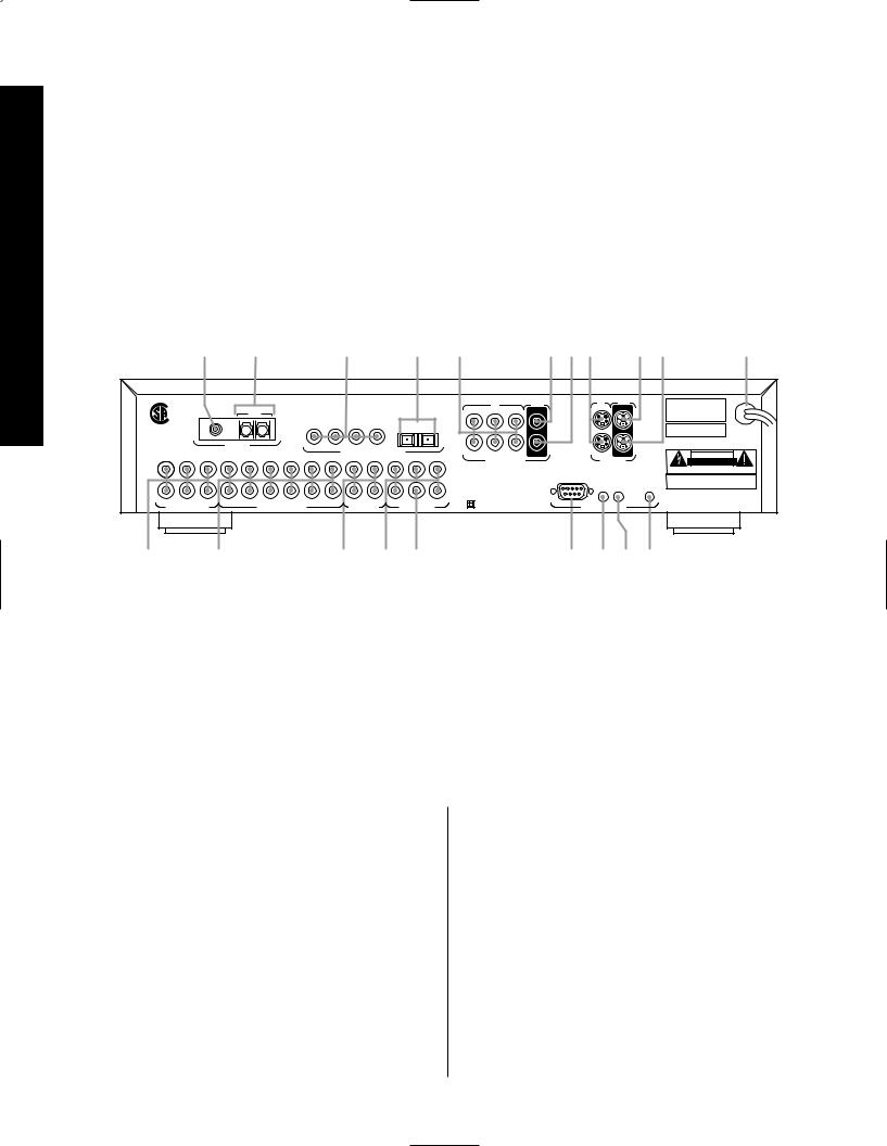
¡ 6-CH Direct Inputs |
• IR Output |
fi Composite Video Main Output |
|
™ Analog Audio Inputs |
ª Trigger Output |
fl Composite Video Inputs |
|
£ Record Outputs |
‚ AC Power Cord |
‡ Optical Digital Audio Inputs |
|
¢ Main Channel Audio Outputs |
⁄ S-Video Record Output |
° Coax Digital Audio Inputs |
|
Subwoofer Output |
¤ S-Video Main Output |
· AM Antenna Input |
|
§ RS-232 Control Port |
‹ S-Video Inputs |
a FM Antenna Input |
|
¶ IR Input |
› Composite Video Record Output |
|
¡ 6-CH Direct Inputs: Use these inputs for connections to optional, external audio adapters. To select a device connected to these jacks, the audio input for a source must be changed to “6-CH Direct” using the Source Menu (see figure OSD-6 on page 29).
™ Analog Audio Inputs: Connect the output of analog audio devices to these inputs. Note the left channel input is on top, and the right channel input is on the bottom. Once the inputs have been connected they may be assigned to any of the 2.0’s seven source positions using the Source Menu (see figure OSD-6 on page 29).
£ Record Outputs: Each of these two pairs of jacks carries the identical audio signal, which is the
audio output selected through the Record Outputs menu (see figures OSD-35 and OSD-36 on pages 48 and 49). Connect these jacks to the “REC IN” input of a VCR, cassette recorder, DAT, reel-to-reel recorder, or another audio recording device.
¢ Main Channel Audio Outputs: Connect these jacks to the input of the audio power amplifier. When making connections to an amplifier make certain that channels are connected to a matching input on the amp. (e.g., front left to front left, center to center, etc.).
10

Signature 2.0
Subwoofer Output Connect this jack to the line level mono input of an optional powered sub-
woofer, or the audio input of an external amplifier used to drive a passive subwoofer. If you are using a passive subwoofer that has both left and right inputs and no indication of which to use for mono subwoofer inputs, it is advisable that a “Y” cable be used so that the signal is fed to both inputs.
§ RS-232 Control Port: This jack is provided to permit operation of the Signature 2.0 by computers or home automation systems. The use of this control port requires additional optional software and it is strongly recommended that a Harman Kardon dealer be consulted before any connections are made.
¶ IR Input: If the 2.0’s front panel IR sensor is blocked due to cabinet doors or other obstructions, an external IR sensor may be used. Connect the output of the sensor to this jack.
• IR Output: This jack may be connected to other compatible Harman Kardon products so that they will receive infrared commands captured by the 2.0’s remote sensor.
ª Trigger Output: If a compatible Signature Series or Harman Kardon audio power amplifier will be used with the 2.0, connect the amplifier connection cable supplied with the 2.0 between this jack and the “Trigger Input” of the amplifier. When connected by a properly trained dealer or installer, this output may also be used to control other devices designed to accept a 6- to 12-volt “Power On” trigger signal, such as projection television screens or automatic blinds. The MAXIMUM current draw for all circuits connectd to this output is 150 milliamperes.
‚ AC Power Cord: Connect this plug to an unswitched, wall-mounted AC outlet.
⁄ S-Video Record Output: Connect this jack to the S-Video “REC-IN” input of a VCR.
¤ S-Video Main Output: Connect this jack to the S-Video input of the TV, video monitor, projector or display that will be used to view the On-Screen Control Menus of the 2.0 along with any selected S-Video input.
‹ S-Video Inputs: Connect the output of S-Video sources to these input jacks. Once the inputs have been connected they may be assigned to any of the 2.0’s seven source positions using the Source Menu (see figure OSD-5 on page 27).
› Composite Video Record Output: Connect this jack to the composite video “REC-IN” input of a VCR.
fi Composite Video Main Output: Connect this jack to the composite video input of a TV set, video monitor, projection television or other video display device that will be used to view the On-Screen Control Menus of the 2.0 along with the selected video input.
fl Composite Video Inputs: Connect the output of composite video sources to these input jacks. Once the inputs have been connected they may be assigned to any of the 2.0’s source positions using the Source Menu (see figure OSD-5 on page 27).
‡ Optical Digital Audio Inputs: Connect the Optical (TosLink) digital audio output of audio sources to these jacks. Once the inputs have been connected they may be assigned to any of the 2.0’s source positions using the Source Menu (see figure OSD-5 on page 27).
° Coax Digital Audio Inputs: Connect the coax digital audio output of audio sources to these jacks. Once the inputs have been connected they may be assigned to any of the 2.0’s source positions using the Source Menu (see figure OSD-5 on page 27).
· AM Antenna Input: Connect the AM loop antenna supplied with the 2.0 to these terminals. An external AM antenna may also be connected here.
a FM Antenna Input: Connect an FM antenna to these terminals. Note that the supplied 300-ohm to
75-ohm adapter is required for connections from twinlead dipole antennas.
Connections Panel Rear
11

Remote Control Operation
Signature 2.0
Remote Control Operation
c
d b
Sending 
 Learning
|
Use |
Learn |
|
|
|
a |
e |
|
|
|
|
||
Source |
Source |
Main |
Main |
|
|
|
|
|
|
||||
f |
Off |
On |
Off |
On |
|
` |
g |
TV |
Store |
RDS |
Type |
Presets |
z |
|
Mono+ Music Movies Stereo |
|||||
|
Vid 1 |
yx |
||||
|
Vid 2 |
Display |
1 |
2 |
3 |
|
|
Vid 3 |
|
4 |
5 |
6 |
w |
|
|
|
7 |
8 |
9 |
|
h |
Simul |
|
|
|||
Tuner |
|
|
0 |
Enter |
|
|
|
|
Disc/Track |
uv |
|||
|
CD |
|
|
|
|
|
|
Tape |
|
|
|
|
t |
|
|
|
|
|
|
|
|
Aux |
|
|
|
|
|
|
|
|
|
|
Mute |
s |
|
|
Menu |
|
|
|
|
i |
|
|
|
|
|
|
|
|
|
|
|
|
|
j |
|
|
|
TV |
|
|
|
Treble |
Sub |
Center |
Volume |
r |
|
kl |
Volume |
|||||
Bass |
Balance |
Surr |
|
|
|
|
m |
|
|
|
|
|
|
n |
|
|
|
|
|
|
o p q
a Main Power On/Off
b Learn LED
c IR Transmitters
d Sending LED
e Use/Learn Switch
f Source Power On/Off
g Source Selection
h Simulcast Button
i Menu Control Buttons
j Menu Button
k Treble Cut
l Subwoofer Trim
m Bass Boost
n Balance Control
o Center Mode
pSurround Control
q TV Volume
r Main Volume Controls
s Mute
t Transport Controls
u Disc/Track
v Enter
w Numeric Keys
x Display
y Surround Mode Selectors
z Preset Tuning
` RDS Type Search
 RDS ID/Text
 Store
Store
 Battery Compartment
12

Signature 2.0
Although the basic functions of the Signature 2.0 may be operated from the front panel, most operation will be controlled through the wireless remote. The remote is a powerful tool, and it is worth taking a few minutes to familiarize yourself with the interaction of the various controls. In addition to the functions listed below, the 2.0’s remote may be programmed to operate most infrared controlled products on the market. For complete information on how to program the remote, read
pages 17-18.
a Main Power On/Off: Press these buttons to turn the 2.0 on or to place it in the standby mode.
NOTE: The Master Power Switch 1must be in the “ON” position for these, or any other buttons on the remote to operate any function on the 2.0.
b Learn LED: This indicator will illuminate when a button on the remote is being programmed with signals from another remote during the “learning” mode. The light will go out when the signal is received
and memorized.
c IR Transmitters: Behind this translucent panel are the infrared transmitters that send signals from the remote unit to the 2.0. When pressing buttons to issue commands, point this area towards the 2.0.
d Sending LED: This indicator should flash any time a button is pressed to confirm that a command is being sent to the receiver of another unit. If the light is dim or does not illuminate when a button is pressed the batteries in the remote should be replaced.
e Use/Learn Switch: This switch selects the operation mode of the remote control. Slide it to the left for normal operation. Slide it to the right when the remote is being programmed.
f Source Power On/Off: Pressing these buttons will send a turn-on, turn-off command to the source device last accessed by pressing one of the Source Selection buttons g. Note that these commands may require programming of the remote control as explained on pages 17-18.
g Source Selection: Pressing these buttons will select the input source for the 2.0. It will also activate the transport and numeric control buttons associated with that device, enabling control of the source with the
2.0 remote. If the 2.0 is in the Standby mode when one of these buttons is pressed, the unit will automatically turn on and switch to the selected input.
h Simulcast Button: Using this button enables you to listen to one source while you watch the video from another. To use the Simulcast feature, first press the Source Selection button gfor the desired video source, followed immediately by pressing this button. Release the Simulcast button, and press the desired audio source within 5 seconds.
i Menu Control Buttons: These buttons control the location of the on-screen cursor to select items from on-screen menus, and they also act to select, move, increase or decrease items from control functions. The ›button is often used to move from a main menu to a sub-menu, the ‹and ›buttons are used to select choices within menus, and the ⁄and ¤ buttons are used to move up and down through lists of selections.
j Menu Button: This button is used to activate the On-Screen Menu Control System when it is not being used, or to enter selections and exit from the control system when it is active.
k Treble Cut: Press this button to activate the Treble Cut feature. When the button is pressed a menu will appear on the screen (see figure OSD-19 on page 40), and you may reduce the high-frequency level of the output by pressing the ‹or ›Menu Control buttons i. When you have completed the adjustment, press this button again to enter the setting and remove the menu from the screen.
l Subwoofer Trim: Press this button to activate the Subwoofer Trim feature. When the button is pressed a menu will appear on the screen (see figure OSD-21
on page 40) and you may adjust the subwoofer output volume by pressing the ‹or ›Menu Control buttons i. When you have completed the adjustment, press this button again to enter the setting and remove the menu from the screen.
Operation Control Remote
13

Remote Control Operation
Signature 2.0
m Bass Boost: Press this button to activate the Bass Boost feature. When the button is pressed a menu will appear on the screen (see figure OSD-20 on page 40) and you may adjust the subwoofer output volume by pressing the ‹or ›Menu Control buttons i. When you have completed the adjustment, press this button again to enter the setting and remove the menu from the screen.
n Balance Control: Press this button to activate the Balance Control feature. When the button is pressed a diagram will appear on the screen (see figure OSD-9
on page 31) that shows a small circle as the current listening position. To adjust the front/back fade and left/right balance use all four Menu Control buttons ito “move” the listening position with respect to the center of the room. Press this button again to enter the setting and remove the diagram from the screen.
o Center Mode: Press this button to select the center mode. When the button is pressed a menu will appear on the screen (see figure OSD-22 on page 41) and you may then make a selection using the ‹or › Menu Control buttons i. Press the button again to enter the setting and remove the menu from the screen.
p Surround Control: Press this button to turn the surround channel output off or on. When the button is pressed a menu will appear on the screen (see figure OSD-23 on page 41) and you may then make a selection using the ‹or ›Menu Control buttons i. Turning the surround channel feed off with this control will change the setting only until the source is changed, at which point the setup configuration selected in the Spkr Setup Menu will take effect. Press the button again to enter the setting and remove the menu from the screen.
IMPORTANT NOTE: Adjustments made using the Treble Cut, Subwoofer Trim, Bass Boost,
Balance Control, Center Mode and Surround Control buttons k l m n o pare temporary. When the mode or input source is changed, or the 2.0 is turned off, the adjustment is canceled and the system preset will return. To make a permanent change to any of these settings, use the Effects Menu, as described on page 30.
q TV Volume: These buttons may be used to control the volume of a TV or other audio device not connected to the 2.0. When shipped from the factory, the buttons will control television sets with the popular RC-5 remote code system. To use these buttons to control other television sets you must program the codes into the remote as described on page 35.
r Main Volume Control: These buttons control the unit’s volume. Note that all channels are controlled simultaneously.
s Mute: Press this button to temporarily silence the audio output of the receiver. Press it again to return to the previous volume level.
t Transport Controls: These buttons may be programmed to control the transport functions of compatible VCR’s, DVD player, CD player, cassette decks, and other source equipment by following the instructions on pages 17 and 18. As shipped from the factory, the remote will control compatible Harman Kardon CD players and cassette decks when the CD or Tape Source Selection buttons ghave been pressed. Some of these buttons also have specific functions to operate the 2.0’s tuner when it is selected.
a)The ‡and ·buttons are used for seek tuning. Each press of these buttons will cause the tuner to search for the station with the next higher or
lower frequency that has a signal strong enough for acceptable reception.
b)The ‚and — buttons may be used to manually tune stations in single frequency increments or, by pressing and holding one of these buttons, it is possible to quickly tune to a specific station.
u Disk/Track: When a compatible Harman Kardon CD player or cassette deck is in use, this button has different functions. It may also be re-programmed to any compatible IR code function following the instructions on page 18.
a)When CD is selected and the unit is a CD changer, these buttons will change to the next disc or previous disc Â.
14

Signature 2.0
b)When Tape 1 is the input source, and the tape machine is a compatible Harman Kardon dual cassette deck, these buttons will switch between the “A” and “B” wells.
v Enter: Press this button to select a station after you have entered its frequency or preset location using the Numeric Keys w.
w Numeric Keys: Press these buttons to access a radio station’s frequency or to enter a station to a specific preset location. See page 44 for complete information on tuning stations and programming preset memories. When other inputs are in use these keys may be programmed to use with TV, CD, and VCR functions that require numeric inputs. When shipped from the factory, the remote is programmed with the RC-5 control codes that activate many popular brands. It may also be re-programmed for use with most compatible infrared control systems by following the instructions on page 17.
x Display: Press this button to show the details of the current input source via the On-Screen Display
System. When a digital input is in use, the comprehensive display (see figure OSD-26 on page 42) will also show information about the AC-3* data being processed. Press it again to remove the display from the screen.
y Surround Mode Selectors: Press these buttons to select a Surround mode for the current listening session. Note that the selection of available modes will change based on the use of an analog or digital input.
a)Pressing the Mono + button will switch between the current surround mode and mono enhancement circuits that create an enveloping soundfield from a mono input.
b)Pressing the Music button will scroll through the list of surround modes that are most appropriate to musical selections.
c)Pressing the Movies button will scroll through the list of surround modes that are most appropriate for movie soundtracks.
d)Pressing the Stereo button will switch between pure two-channel stereo sound and the previously selected surround mode.
IMPORTANT NOTE: Using these buttons will change the surround mode for a current listening session only. Once the input source is changed, the 2.0 will revert
to the surround mode that has been entered using the Source Menu. To permanently change the surround mode that is assigned to an input source, use the Source Menu as described on page 28.
z Preset Tuning: Pressing this button when the tuner is active to scroll up through the list of stations entered into the preset memory.
` RDS Type Search: When the FM tuner is active, press this button to initiate a search for a station with a specific program type. For more information on RDS tuning, see page 46.
 RDS: When the 2.0 is tuned to an FM station that is transmitting RDS data, press this button once to display the station’s Text message. Press it again to view information that the station is transmitting about the station’s call letters, network affiliation or other identifying information, as well as the station’s program type (PTY). See page 46 for complete information on using the RDS system.
 Store: When the tuner is in use, press this button to enter a station into the preset memory after selecting a location number between 1 and 30 using the Numeric Keys w.
 Battery Compartment: Insert fresh AAA batteries here, being certain to observe proper polarity by matching the ( ) and (Â) indications on both the batteries and case. To remove the cover press down slightly on the raised ridges and gently push the cover away from you. To replace the cover, slide it back towards you until you hear the latch click.
Operation Control Remote
15
Remote Control Programming
Signature 2.0
Remote Control Programming
This product is equipped with a powerful remote control. As supplied, it will operate the 2.0, as well as most CD players and tape decks manufactured by Harman Kardon. If your equipment requires different codes, it may be programmed to copy the codes from most infrared remotes.
Loading Batteries
The life of the batteries for the remote control is about one year in normal operation. If the amber Sending LED ddoes not flash when remote buttons are pushed, that is an indication that the batteries need to be replaced.
To change the batteries:
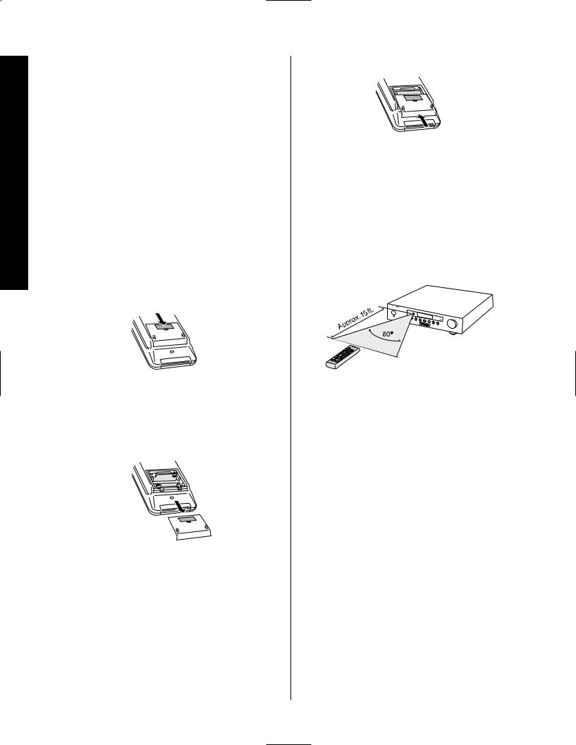
1. Remove the back cover by sliding it in the direction of the arrows.
3. Close the cover until it clicks shut.
NOTE: It is important that the batteries be replaced within ten minutes after the old batteries are removed to avoid losing any remote codes that have been programmed into the remote’s memory.
Remote Control Range
The remote will operate at a range of up to 15 feet from the unit, when the batteries are fully charged. The remote will also operate at an angle of up to 30° to either side of the unit.
2.0
DVD |
|
|
Dolby |
Digital |
Vol |
|
|
10 |
2. Remove the old batteries and insert fresh AAA type |
Always point the remote transmitter at the front of the |
|
cells. Be certain to observe the correct polarity by noting |
||
unit when issuing commands. If you find that remote |
||
the ( ) and (Â) marks on both the inside of the case |
||
commands are not being received by the remote, it may |
||
and on the battery cells. It is recommended that both |
||
be necessary to use a remote IR sensor. |
||
batteries be changed at the same time. |
||
|
16

Signature 2.0
Programmable Keys
Many of the buttons on the remote control may be user programmed to new functions to operate virtually any component in your system. Eleven CANNOT be
programmed with a new code, as they control high-level functions of the 2.0. These keys are Main Power On, Main Power Off, and the nine source input keys:
TV, Vid 1, Vid 2, Vid 3, Tuner, CD, Tape 1
and Aux.
Programmable keys are divided into two groups. Some keys may be programmed with a separate function for each of the inputs. Thus, these keys may change their code when the input source is changed. (e.g., the Play key may transmit a different code when CD is selected as opposed to when VCR is selected.) The keys that may be programmed with multiple codes are the following:
All Numeric Keys (0 – 9)
Source Power On
Source Power Off
Stop
Disc/Track
Record
Pause
Channel/Preset Up
Channel/Preset Down
Tune Up
Tune Down
P-Scan
TV Volume Up/Down
Display
Store
RDS
Type
Presets
All other keys may only be programmed with one remote code. The code contained in these keys remains the same regardless of the source selection.
WARNING: These keys transmit codes that are vital to the operation of the product. It is not recommended that they be programmed with alternative codes, as it may then be impossible to operate certain functions of the receiver.
Menu
All Navigation Buttons ‹›⁄¤
Enter
All Mode Selectors
Treble
Sub
Center
Bass
Balance
Surr
Mute
Simulcast
Programming Control Remote
17
Remote Control Programming
Signature 2.0
To program the remote, follow these steps. Note that it is not necessary to program all keys, only those that are required to operate the subject device. Keys not programmed will retain the codes preprogrammed at the factory.
1.Slide the Use/Learn switch eat the top left corner of the remote to the right so that it is next to Learn.
2.If one of the multifunction buttons is being programmed press the source button (e.g., CD, Vid 1) you wish to have this function associated with. If you are programming a single function key, proceed to the next step.
3.Press the button on the remote that is to be programmed. Note that the Learning LED b will illuminate.
4.Place the 2.0’s remote head to head with the other remote control whose function is being learned. The two remotes should be no more than 8 inches apart.
5.Press and hold the button on the other remote corresponding to the function to be memorized until the Learning LED starts to blink. When the LED goes out, release the button on the transmitting remote. The function code has been successfully captured by the 2.0’s remote.
NOTE: If both LEDs flash during a programming operation, it indicates that the remote’s memory is full or that the remote codes from the transmitting remote are not compatible with the unit’s signal format.
6. Continue to program any additional remote commands required using steps 2 through 5. When you have finished programming the remote, slide the Use/Learn switch eto the left so that it is in the Use position.
Resetting the Remote Memory
In normal operation, codes for a new device may be programmed “over” the codes that have been previously programmed into the remote. It is also possible to reset the memory for individual keys, or for the entire remote. When a memory position is reset, the remote will return to the original factory preset command.
To reset the memory for a specific individual key location, put the Use/Learn switch in the Learn position. Press the Main Power Off button aand the button to be reset at the same time. Both the Sending and Learning indicators will light momentarily. When the lights go out, the memory has been cleared of the user programmed code and reset to the factory preset. Return the Use/Learn switch eto the Use position when you are finished.
To reset the remote’s entire memory and return all keys to their factory preset commands first put the Use/Learn switch ein the Learn position. Then press the Main Power On button aand confirm that the Learn LED bhas illuminated. While con-
tinuing to press the Main Power On button, press and hold the Main Power Off button abutton until the Learn LED goes off for about 3 seconds. It will then blink twice. Then release the two buttons. This indicates that the memory has been cleared of any
user programmed commands and that the original commands have been restored. Slide the Use/Learn switch eback to the Use position to return the remote to normal operation.
18
 Loading...