


harman/kardon
HKSUB 12
Powered Subwoofer
SERVICE MANUAL
harman/kardon, Inc. |
|
250 Crossways Park Dr. |
|
Woodbury, New York 11797 |
Rev1 9/2004 |
HKSUB12 |
harman/kardon |
|
|
|
CONTENTS |
|
|
|
BASIC SPECIFICATIONS . . . . . . . . |
. . . . . . . |
. . . . . . . . . . .. . . . . ... . ... . . .. .. . .. . |
.. .. .. . . . . . 1 |
|
DETAILED SPECIFICATIONS . . . . . |
………………... ……………. .. ………... . . .. . . . . .. . … . |
.2 |
||
CONTROLS & CONNECTIONS . . . . |
. . . . . . . |
. . .. . . . . . . . . … . . . . .. . . . . . . . . . .. . . .. . . . . 3 |
||
CONNECTION GUIDE………... . . . . . . . . . . . . .. . . . . . . . . …... . . . . . .. . . . . . . . . .. . . . . . . . . 5 |
||||
CONFIGURING RECEIVER/PROCESSOR…………………..……………..……. . . . .. . .. . . . . . . 8 |
||||
OPERATION……. . . . . .. . . . . . . . .. .. . . . .. .. . . . . …………………….……….. . . . .. . .. . . . . . . 9 |
||||
BASIC TROUBLESHOOTING GUIDE………………………………………………………….. . . . .10 |
||||
HKSUB 12 EXPLODED VIEW. . . . ………………... ……………. .. ………... . . .. . .. .. . . .. . … . 11 |
||||
HKSUB 12 AMPLIFIER EXPLODED VIEW. . . . |
………………... . .. ………... . . .. . .. .. . . .. . … . 12 |
|||
HKSUB 12 BLOCK DIAGRAM . . . . . |
. . . . . . . |
. .. . . . . . . ……………… . . . . . . .. . |
.. .. . . . . . . 13 |
|
HKSUB 12 TEST PROCEDURE. .. . . . |
. . . . . . . |
. . . .. . . . . ……… ………….... . . . .. . .. .. . . . . . 14 |
||
HKSUB 12 PCB DRAWINGS. .. . . . . . . |
. . . . . . . |
.. . . . . ……… . …………. . . . . . . .. . .. .. . . . . . 15 |
||
HKSUB 12 ELECTRICAL PARTS LIST …………. .... . .. . . . . ………….…….. . . . . . .. . .. .. . . . . 17 |
||||
HKSUB 12 MECHANICAL/PACKING PARTS LIST …………. .... . .. . . . . …... . . . . . .. . .. .. . . . . 20 |
||||
HKSUB 12 IC – TRANSISTOR PINOUTS . … . . |
.. . . . . . . ………………….………... . .. .. . . . . . 21 |
|||
HKSUB 12 SCHEMATIC DIAGRAMS . |
. . . . . . . .. |
.. .. .. . . . .. . ……………….……... . . . . . . . . . .22 |
||
HKSUB 12 PACKAGE………... . . . . . . . . . . . . .. . . . . . . . . …... . . . . . .. . . . . . . . . .. . . … . . . . |
.25 |
|||
SPECIFICATIONS |
|
|
|
|
Amplifier Power (RMS) |
150 Watts |
|
|
|
Driver |
12" Polymer-coated-cone woofer |
|
|
|
Inputs |
Stereo Line Level, dedicated Subwoofer (LFE) |
|
||
|
and Speaker Level with gold-plated 5-way binding posts |
|||
Outputs |
Speaker Level with gold-plated 5-way binding posts |
|
||
Low-Pass |
Frequency Continuously variable from 50Hz – 150Hz |
|||
Frequency Response |
25Hz – low-pass crossover setting |
|
|
|
Dimensions |
(H x W x D) 20-1/2" x 16" x 13-3/4" |
|
|
|
|
(520mm x 401mm x 350mm) |
|
|
|
Weight |
40 lb/18kg |
|
|
|
Occasional refinements may be made to existing products without notice but will always meet or exceed original specifications unless otherwise stated.
1

HKSUB12 |
|
|
|
|
|
harman/kardon |
||
|
|
|
|
|
|
|
|
|
|
|
|
|
|
|
|
|
|
|
HK SUB12 |
150W Powered Amplifier |
|
|
|
|
||
|
|
|
|
|
|
|
|
|
|
LINE VOLTAGE |
Yes/No |
Hi/Lo Line |
Unit |
Notes |
|
|
|
|
US 120vac/60Hz |
Yes |
108-132 |
Vrms |
Normal Operation |
|
|
|
|
|
|
|
|
|
|
|
|
|
Parameter |
Specification |
Unit |
QA Test Limits |
Conditions |
|
Notes |
|
|
Amp Section |
|
|
|
|
|
|
|
|
Type (Class AB, D, other) |
D |
D |
n/a |
|
|
|
|
|
Load Impedance (speaker) |
4 |
Ohms |
n/a |
Nominal |
|
|
|
|
Rated Output Power |
150 |
Watts |
150 |
1 input driven |
|
|
|
|
THD@ Rated Power |
0.08 |
% |
1 |
22k filter |
|
|
|
|
THD @ 1 Watt |
0.15 |
% |
0.5 |
22k filter |
|
|
|
|
DC Offset |
5 |
mV-DC |
30 |
@ Speaker Outputs |
|
|
|
|
|
|
|
|
|
|
Measured at speaker terminals, Output |
|
|
Damping factor |
>100 |
DF |
30 |
|
|
power 140 Watts THD 0.1 % |
|
|
|
|
|
|
|
|
|
|
|
Input Sensitivity |
|
|
|
|
|
|
|
|
Input Frequency |
50 |
Hz |
NA |
Nominal Freq. |
|
1 input driven |
|
|
Line Input (L&R) |
220 |
mVrms |
±2dB |
To Rated Power |
|
1 input driven |
|
|
LFE (Sub) Input |
220 |
mVrms |
±2dB |
To Rated Power |
|
LFE input driven only |
|
|
Speaker/Hi Level Input |
2.2 |
Vrms |
±2dB |
To Rated Power |
|
(-20 dB below Line In)...1 input driven |
|
|
|
|
|
|
|
|
|
|
|
Signal to Noise |
|
|
|
|
|
|
|
|
SNR-A-Weighted |
100 |
dBA |
85 |
rel. to rated power |
|
A-Weighting filter |
|
|
SNR-unweighted |
90 |
dBr |
80 |
rel. to rated power |
|
22k filter |
|
|
SNR @ 1W-unweighted |
65 |
dBr |
60 |
rel. to 1W Output |
|
22k filter |
|
|
|
|
|
|
Volume @max, using RMS reading |
|
|
|
|
Residual Noise Floor |
1.2 |
mVrms |
3.0 |
DMM/VOM (or A/P) |
|
|
|
|
|
|
|
|
Volume @max, w/ A/P Swept Bandpass |
|
|
|
|
Residual Noise Floor |
0.8 |
mVrms(max) |
2.0 |
Measurement (Line freq.+ harmonics) |
|
|
|
|
|
|
|
|
|
|
|
|
|
Input Impedance |
|
|
|
|
|
|
|
|
Line input L&R , LFE (Sub) |
10 |
K ohms |
n/a |
Nominal |
|
|
|
|
Speaker/Hi Level Input |
4.7 |
K ohms |
n/a |
Nominal |
|
|
|
|
|
|
|
|
|
|
|
|
|
Filters |
|
|
|
|
|
|
|
|
Left & Right Low Pass fixed |
130 Hz |
-- |
±2dB |
@ -3dB ref. 100Hz |
|
|
|
|
LFE Low Pass fixed |
220 Hz |
-- |
±2dB |
@ -3dB ref. 100Hz |
|
|
|
|
Subsonic filter (HPF) |
22 Hz |
-- |
±2dB |
@ -3dB ref. 100Hz |
|
|
|
|
|
|
|
|
|
|
|
|
|
Limiter |
YES |
-- |
n/a |
|
|
|
|
|
|
|
|
|
|
|
|
|
|
Features |
|
|
|
|
|
|
|
|
LFE(Sub) Input |
YES |
|
functional |
|
|
BW Limited to 220 Hz |
|
|
Volume pot Taper (lin/log) |
log |
-- |
functional |
|
|
|
|
|
ATO |
YES |
|
functional |
|
|
|
|
|
|
|
|
|
|
|
|
|
|
Signal Sensing (ATO) |
|
|
|
|
|
|
|
|
ATO test Frequency |
50 |
Hz |
n/a |
|
|
|
|
|
ATO Line Level |
4.0 |
mV |
2.0 - 8.0 |
driven |
. |
|
|
|
ATO Speaker level input |
40 |
mV |
20 - 80 |
driven |
|
|
|
|
|
|
|
|||||
|
|
|
|
|
Amp connected and AC on, then input |
|
|
|
|
ATO Turn-on time |
5 |
ms |
functional |
signal applied |
|
|
|
|
Auto Mute/ Turn-OFF Time |
15 |
minutes |
10 - 25 |
T before muting, after signal is removed |
|
|
|
|
|
|
|
|
|
|
|
|
|
Power on Delay time |
3 |
sec. |
functional |
AC Power Applied |
|
|
|
|
|
|
|
|
|
|
|
|
|
Transients/Pops |
|
|
|
|
|
|
|
|
ATO Transient |
5 |
mV-peak |
10 |
@ Speaker Outputs |
|
|
|
|
Turn-on Transient |
50 |
mV-peak |
100 |
@ Speaker Outputs |
|
AC Line cycled from OFF to ON |
|
|
Turn-off Transient |
50 |
mV-peak |
100 |
@ Speaker Outputs |
|
AC Line cycled from ON to OFF |
|
|
|
|
|
|
|
|
|
|
|
Efficiency |
|
|
|
|
|
|
|
|
|
|
|
|
|
|
Maximum allowable input power under |
|
|
|
|
|
|
|
|
nominal Input voltage and frequency, HOT |
|
|
Stand-by Input Power |
10 |
Watts |
12 |
@ nom. line voltage |
|
or COLD operation. |
|
|
Power Cons.@rated power |
230 |
Watts |
250 |
@ nom. line voltage |
|
150 Watts @ 4 Ohms nominal line voltage |
|
|
|
|
|
|
|
|
|
|
|
Protection |
|
|
|
|
|
|
|
|
Short Circuit Protection |
YES |
-- |
functional |
Direct short at output |
|
|
|
|
|
|
|
|
|
|
Temperature rise should not exceed 35K |
|
|
Thermal Protection |
65 deg. C |
-- |
functional |
@1/8 max unclipped Power |
|
rise |
|
|
DC Offset Protection |
YES |
-- |
functional |
DC present at Speaker Out leads |
|
Relay or crowbar (for driver/fire protection) |
|
|
Line Fuse Rating |
|
|
|
|
|
|
|
|
US Version |
3.15 |
Amps |
|
Type-T or Slo Blo |
|
External fuse with UL/SEMKO rated holder |
|
2

HKSUB12 |
harman/kardon |
AMPLIFIER PANEL CONTROLS AND CONNECTIONS
£ ¢∞ § ¶ •
R L
™
¡
IMPORTANT: CONNECT STRIPED WIRE TO RED (
LINE |
|
|
|
|
|
LEVEL |
GREEN: ON |
|
|
|
|
IN |
|
|
|
||
RED: STAND-BY |
FILTER |
|
|||
|
|
||||
SUB |
AUTO |
ON |
OFF |
ON |
|
|
|
|
|
|
|
L |
|
100Hz |
|
|
ª |
|
|
|
|
|
‚ |
R |
|
|
|
|
|
NORMAL |
REVERSE |
50Hz |
150Hz |
MIN |
MAX |
PHASE |
CROSSOVER |
SUBWOOFER |
) SPEAKE R TERMINAL. |
FREQUENCY |
LEVEL |
|
|
¡ Speaker-Level Inputs
™ Speaker-Level Outputs
£ Line-Level Full-Range Inputs
¢ Line-Level Subwoofer (SUB) Input
∞ Phase Switch
§ Music-Sense On/Off Switch
¶ LED Indicator
• High-Cut (Low-Pass) Filter Switch
ª Crossover Frequency Control
‚ Subwoofer Level Control
⁄ Master Power Switch
¤ AC Power Cord
HKSUB 12 |
|
Made in China |
POWER |
|
|
|
⁄ |
|
AC 120V~60Hz |
|
250 Watts |
CAUTION |
¤ |
RISK OF ELECTRIC SHOCK |
|
DO NOT OPEN |
|
¡ Speaker-Level Inputs: If your receiver or amplifier does not have a line-level subwoofer output, connect these binding post terminals to the main left and right speaker terminals of your receiver or amplifier. Remember to maintain polarity
by connecting the (+) terminal on the receiver/amplifier to the (+) terminal on the HKSUB 12 subwoofer, and the (–) terminal on the receiver/ amplifier to the (–) terminal on the HKSUB 12 subwoofer.
™ Speaker-Level Outputs: If you are using the Speaker-Level Inputs ¡ on the HKSUB 12, connect these binding post terminals to your front left and right speakers,
remembering to maintain polarity by connecting the (+) terminal on the HKSUB 12 subwoofer to the (+) terminal on the speaker, and the (–) terminal on the HKSUB 12 subwoofer to the (–) terminal on the speaker. If you are not using the Speaker-Level Inputs ¡, connect your front left and
right speakers directly to your receiver or amplifier. See pages 9 through 12 for
further information on speaker connections.
£ Line-Level Full-Range Inputs: Connect the full-range, unfiltered line-level subwoofer output or preamp output(s) of your receiver or amplifier to these inputs. If your receiver does not have a separate subwoofer output, use a
Y-adapter (not supplied) to bridge the receiver’s preamp output to the main amp input for that channel, and connect the long end of the adapter to the corresponding line-level input on the HKSUB 12. If your receiver has only a single subwoofer output, you may connect it to either the left or right line-level input on the HKSUB 12, and no Y-adapter is needed.
¢ Line-Level Subwoofer (SUB) Input:
Connect the filtered subwoofer output of a receiver to this input. This input bypasses the HKSUB 12’s internal crossover circuitry,
3
2 AMPLIFIER PANEL CONTROLS AND CONNECTIONS

HKSUB12 |
harman/kardon |
|
|
AMPLIFIER PANEL CONTROLS AND CONNECTIONS
and should only be used with a filtered signal. If your receiver does not have a filtered subwoofer output, you should use the LineLevel Full-Range Inputs £ instead.
∞ Phase Switch: This switch determines whether the HKSUB 12 subwoofer’s pistonlike action moves in and out in phase with the main speakers. If the speakers are out of phase, the sound waves produced by the subwoofer will be cancelled out, reducing bass response. This phenomenon depends in part on the relative placement of the speakers in the room. In most cases, the Phase Switch ∞ should be left in the NORMAL position. However, it does no harm to experiment with the Phase Switch ∞, and you may leave it in the position that maximizes bass response.
§ Music-Sense On/Off Switch: When this switch is placed in the AUTO position, and when the Master Power Switch ⁄ is turned on, the HKSUB 12 will automatically turn on or place itself in the Standby mode, depending on whether it is receiving an audio signal. When this switch is placed in the ON position, the HKSUB 12 will remain on, whether or not it is receiving an audio signal.
¶ LED Indicator: This LED indicates whether the HKSUB 12 is in the ON or STANDBY state when used with
the Music-Sense On/Off Switch § in the AUTO position. The LED is lit green to indicate that the HKSUB 12 is receiving an audio signal and is turned on, and the LED is lit red to indicate that no signal is being received and the HKSUB 12 is in Standby mode.
When the Music-Sense On/Off Switch
§ is in the ON position, the LED will be lit green, whether or not an audio signal is present.
When the Master Power Switch ⁄ is turned off, the LED goes dark, no matter
which position the Music-Sense On/Off Switch § is in.
• High-Cut (Low-Pass) Filter Switch:
Placing this switch in the ON position activates circuitry that filters out all audio input signals above the setting of the Crossover Frequency Control ª. This allows the HKSUB 12 to focus its power on reproducing the low-frequency portion of the signal, avoiding inefficiency and distortion. Engage this filter when using the Speaker-Level Inputs ¡, or when using the Line-Level Full-Range Inputs £, unless your receiver or processor processes its line-level output using a low-pass filter. The filter has no effect when the SUB Input ¢ is used.
ª Crossover Frequency Control: Adjust this control to set the highest frequency the HKSUB 12 will reproduce. You should begin by setting it slightly above the
lowest frequency that your main speakers are capable of reproducing. You may safely adjust the crossover frequency later as you listen to different program materials. This control will have no effect if
you are using the Line-Level Subwoofer (SUB) Input ¢, or if you have set the
High-Cut (Low-Pass) Filter Switch • to the OFF position. See page 14 for more information on adjusting the crossover setting.
‚ Subwoofer-Level Control: Volume may be adjusted using the SubwooferLevel Control. Turn the control clockwise to increase the HKSUB 12’s volume, or counterclockwise to decrease it.
⁄ Master Power Switch: Press this rocker switch at the “•” mark to power-on the HKSUB 12 subwoofer. The HKSUB 12 will then be either in the Standby mode or completely on, depending on the position of the Music-Sense On/Off Switch §.
¤AC Power Cord: Plug this cord
into an active, unswitched electrical outlet for proper operation of the HKSUB 12. The cord should not be plugged into the accessory outlets found on some audio components.
4 |
3 |
AMPLIFIER PANEL CONTROLS AND CONNECTIONS |

HKSUB12 |
harman/kardon |
|
|
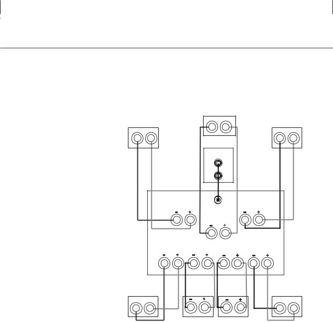
SPEAKER CONNECTION GUIDE
Analog Receiver/Processor –
Speaker-Level Connections
Use this installation method for analog receivers or processors that do not have digital processing
or bass-management programming, and where the receiver/processor does not have a subwoofer output, or a volume-controlled preamp (line-) level output:
Connect your receiver or amplifier’s front left and right speaker terminals to the left and right Speaker-Level Input ¡ terminals on the HKSUB 12 subwoofer that are marked “High Level In.” Connect
the left and right Speaker-Level Output
™ terminals on the HKSUB 12 subwoofer that are marked “High Level Out” to the corresponding terminals on the back of your front left and right speakers.
Connect your receiver or amplifier’s center, surround, and surround back speaker terminals to the corresponding terminals on the back of your center and surround speakers.
When all connections have been made, plug the AC Power Cord ¤ on the subwoofer into an AC outlet.
Front |
Center |
Front |
||
Left |
Right |
|||
– |
+ |
|||
– |
+ |
|||
+ |
– |
|||
HKSUB 12
Subwoofer
L R
Receiver or Amplifier
Front Left |
|
Center |
Front Right |
Surround Left |
Surround |
Surround |
Surround Right |
Back Left |
Back Right |
Surround |
Surround |
||
Left |
|
|
Right |
– |
+ |
– |
+ |
|
Surround |
Surround |
|
|
Back Left |
Back Right |
|
5
4 SPEAKER CONNECTION GUIDE
HKSUB12 |
harman/kardon |
|
|
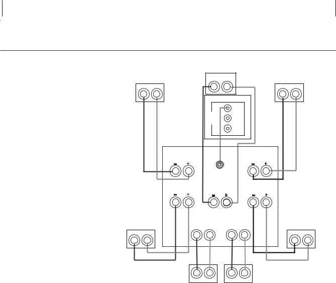
SPEAKER CONNECTION GUIDE
Analog Receiver/Processor –
Line-Level Connections
Use this installation method for analog receivers or processors that do not have digital processing
or bass-management programming, and where the receiver/processor is equipped with an unfiltered subwoofer output, or a volume-controlled preamp (line-) level output:
Use the supplied RCA-type patch cord to connect the line-level subwoofer output on your receiver or amplifier to either the left or right Line-Level Full-Range Input £ on the HKSUB 12 subwoofer. Use both the left and right inputs on the subwoofer if your receiver or processor has both left and right line-level outputs. (You will need to purchase a second 15-foot interconnect cable.)
If your receiver is equipped with line-level outputs but does not have a separate subwoofer output, use a Y-adapter (not supplied) to bridge the receiver’s preamp output to the main amp input for that channel, and connect the long end of the adapter to the corresponding line-level input on the HKSUB 12.
IMPORTANT: Do not use the SUB Input
¢ on the subwoofer with analog receivers or processors that have a full-range subwoofer output, such as models that have Dolby Pro Logic* surround processing,
but not Dolby Digital processing. However, if your analog receiver or processor has
a filtered subwoofer output, such as some THX®-certified models, you may connect it to the SUB Input ¢. Consult your receiver’s or processor’s owner’s manual for more information.
Make sure that you have configured your surround sound processor
for “Subwoofer On.”
When all connections have been made, plug the AC Power Cord ¤ on the subwoofer into an AC outlet.
Connect each speaker to the corresponding speaker terminals on your receiver or amplifier.
Front |
Center |
Front |
||||
– |
+ |
|||||
Left |
|
Right |
||||
|
|
|
||||
– |
+ |
|
|
– |
+ |
|
|
|
HKSUB 12 |
|
|
||
|
|
Subwoofer |
|
|
||
|
|
Line-Level |
|
|
||
|
|
|
L |
|
|
|
|
|
|
R |
|
|
|
|
Front |
|
Front |
|
||
|
Left |
Subwoofer |
Right |
|
||
|
|
|
Out |
|
|
|
|
|
Center |
|
|
||
|
Surround |
Surround |
Surround |
Surround |
|
|
|
Left |
Back Left |
Back Right |
Right |
|
|
Surround |
Receiver or Amplifier |
Surround |
||||
Surround |
Surround |
|||||
Left |
|
Right |
||||
|
Back Left |
Back Right |
||||
– |
+ |
– |
+ |
|||
|
|
|||||
6
5
HKSUB12 |
harman/kardon |
|
|
SPEAKER CONNECTION GUIDE
Connection to Digital
Receiver/Processor
Use this installation method for analog receivers or processors that have Dolby Digital, DTS or other digital surround decoders and bass-management programming, or analog receivers or processors
that have a filtered subwoofer output:
Use the line-level input jack marked SUB ¢ for the Low-Frequency Effects channel. Connect this jack to the subwoofer output or LFE output on your
receiver or amplifier. Connect each speaker to the corresponding speaker terminals on your receiver or amplifier.
Make sure you’ve configured your surround sound processor for “Subwoofer On.”
When all connections have been made, plug the AC Power Cord ¤ on the subwoofer into an AC outlet.
Front |
|
Center |
|
Front |
|
|||
|
– |
+ |
|
|
||||
Left |
|
|
Right |
|
||||
|
|
|
|
|
||||
– |
+ |
|
|
|
|
– |
+ |
|
|
|
|
HKSUB 12 Subwoofer |
|
|
|
||
|
|
|
|
SUB |
|
|
|
|
|
|
|
LINE |
|
|
|
|
|
|
|
|
LEVEL |
R |
|
|
|
|
|
|
|
IN |
|
|
|
|
|
|
|
|
|
L |
|
|
|
|
|
Front |
|
|
|
|
Front |
|
|
|
Left |
|
|
|
|
Right |
|
|
|
|
|
SUB/LFE |
|
|
|
|
|
|
|
|
|
Out |
|
|
|
|
|
Surround |
|
|
|
Surround |
|
|
|
|
Left |
|
Center |
|
Right |
|
|
|
Surround |
Surround |
Surround |
|
Surround |
||||
Left |
|
Back Left |
Back Right |
|
Right |
|||
– |
+ |
– |
+ |
– |
+ |
|
– |
+ |
|
|
|
|
|
||||
|
|
|
Receiver |
|
|
|
|
|
|
|
|
|
or |
|
|
|
|
|
|
|
Amplifier |
|
|
|
|
|
– |
+ |
– |
+ |
Surround |
Surround |
||
Back Left |
Back Right |
||
7
 Loading...