


HKTS 9
HKTS 35BQ
Home theater speaker system
Owner’s Manual

HKTS 35BQ
Introduction, Description and Features,
and Included Items
Introduction
Thank you for purchasing the Harman Kardon® HKTS 35 speaker system, with which
you’re about to begin many years of listening enjoyment. The HKTS 35 has been custom
designed to provide all the excitement and power of the cinema experience in your own
living room.
While sophisticated electronics and state-of-the-art speaker components are hard at
work within the HKTS 35, hookup and operation are easy, thanks to simple controls and
color-keyed cables and connections.
To obtain maximum enjoyment from your new home theater speaker system, we urge you
to take a few minutes to read through this manual. It will help ensure that the connections
you make to your receiver (or preamp/processor), amplier and other devices are correct.
In addition, a few minutes spent learning the functions of the various controls will enable
you to take advantage of all the power and renement the HKTS 35 is able to deliver.
If you have any questions about this product, its installation or its operation, please
contact your dealer. He or she is your best local source of information.
Description and Features
The HKTS 35 is a complete six-piece home theater speaker system that includes:
• A 200-watt wireless powered subwoofer with an 8-inch (200mm) low-frequency
transducer
• Four identical, two-way, video-shielded, dual midrange satellite speakers for the front
left and right, and surround left and right speaker positions
• A dedicated, voice-matched, video-shielded, dual midrange center speaker
• Removable bases for the satellite speakers and wall-mount brackets for the satellite
and center speakers
• All of the cables you need to connect all of the speakers to your receiver or preamp/
processor and amplier
The speaker cables all use a color-coding system to conform to the Consumer Electronics
Association (CEA
connecting the speakers, especially when you are connecting them to a Harman Kardon
receiver.
We have equipped the HKTS 220SUB wireless subwoofer and transmitter with Wireless
Code switches that allow the subwoofer to avoid interference from other wireless devices
while it’s operating wirelessly. Other conveniences include a level control, a phase switch
for ne-tuning bass response to suit your listening environment and taste, and an
efcient switching system that senses the presence of an audio signal and automatically
switches the subwoofer from standby mode to on.
We have included wall-mount brackets for the satellite and center speakers and shelf
stands for the satellite speakers. Optional HKFS 3 oor stands are available separately
from your Harman Kardon dealer.
Harman Kardon engineers invented the high-delity receiver over fty years ago. With
state-of-the-art features and time honored circuit designs, the HKTS 35 is a perfect
complement to a Harman Kardon receiver or any home theater system.
®
) standard. This color-coding system minimizes confusion when
Included Items
SAT-TS30 Satellite
speakers x 4
CEN-TS30 Center
speaker x 1
HKTS 220SUB wireless
subwoofer x 1
Wireless transmitter
power supply x 1
Transmitter power
supply AC cord x 1
(varies with region)
Satellite wall-mount
bracket x 4
Center speaker wall-mount
bracket x 1
Bracket stop
plate x 4
Subwoofer wireless
transmitter x 1
32.8-foot (10m)
speaker cables x 2
16.5-foot (5m)
speaker cables x 2
Trigger cable x 1
13.1-foot (4m)
LFE cable x 1
2
speaker cable x 1
HKTS 35BQ
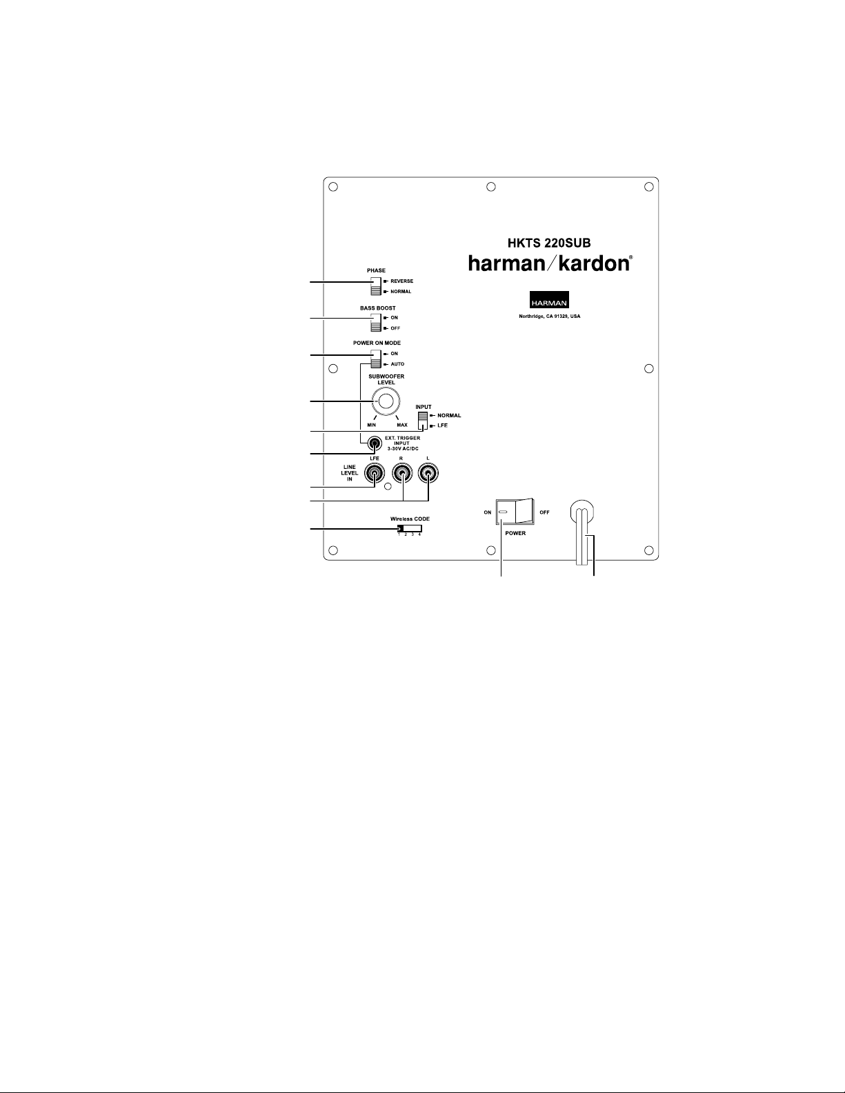
Subwoofer Rear-Panel Controls and Connections
Subwoofer Unit
Phase Switch
Bass Boost Switch
Power On Mode Switch
Subwoofer Level Control
Input Mode Switch
External Trigger Input
Subwoofer Rear-Panel Controls and Connections
Line-Level LFE In Connector
Line-Level L/R In Connectors
Wireless Code Switch
Phase switch: This switch determines whether the subwoofer transducer’s piston-like
action moves in and out in phase with the satellite speakers. If the subwoofer were to
play out of phase with the satellite speakers, the sound waves from the satellites could
cancel out some of the subwoofer’s sound waves, reducing bass performance and sonic
impact. This phenomenon depends in part on the placement of all the speakers in the
room. In most cases, the Phase switch should be left in the “Normal” position. However,
it does no harm to experiment, and you can leave the Phase switch in the position that
maximizes bass response and impact.
Bass Boost switch: Set this switch to “On” to enhance the subwoofer’s low-frequency
performance. Set this switch to “Off” for normal low-frequency performance.
Power On Mode switch: When this switch is set in the “Auto” position and when the
Power switch is set to “On,” the subwoofer will automatically turn itself on when it
receives an audio signal and will enter the standby mode after it has received no audio
signal for about 15 minutes. When this switch is set in the “On” position, the subwoofer
will remain on whether or not it is receiving an audio signal. An LED on the subwoofer’s
top panel indicates whether the subwoofer is in the on or standby state:
• When the LED glows white, the subwoofer is turned on.
• When the LED is not illuminated, the subwoofer is in the standby mode. When the
Power switch is set to “Off,” the LED will not be illuminated, no matter what setting
the Power On Mode switch is in.
Subwoofer Level control: Use this control to adjust the subwoofer’s volume. Turn
clockwise to increase the volume; turn counterclockwise to decrease the volume.
Input Mode switch: When this switch is in the “Normal” setting, the input signal from
the Line-Level L/R In connectors is active. When this switch is in the “LFE” setting, the
input signal from the Line-Level LFE In connector is active.
External Trigger Input connector: Use the supplied trigger cable to connect the External
Trigger Input connector to the trigger output of another compatible component. Whenever
the subwoofer detects a trigger signal between 3V and 30V (AC or DC), its amplier will
turn on. The amplier will turn off after the trigger signal ceases, even when the Power
On Mode switch is in the “Auto” position.
Power Switch Power Cord
Line-Level LFE In connector: The signal from this connector bypasses the subwoofer’s
internal low-pass crossover. When you’re connecting the subwoofer to the dedicated
subwoofer output of a receiver/processor that has its own low-pass crossover network,
use the Line-Level LFE In connector. You must also set the subwoofer’s Input Mode
switch in the “LFE” position.
Line-Level L/R In connectors: The signals from these connectors pass through the
subwoofer’s internal low-pass crossover. When you’re connecting the subwoofer to
the preamp or subwoofer outputs of a receiver/processor that does not have its own
low-pass crossover network, use both Line-Level L/R In connectors. You must also set
the Input Mode switch in the “Normal” position. If your receiver/processor has only one
subwoofer output, you can use either the L or R connector.
Wireless Code switch: This switch selects between four different channels for the
wireless subwoofer signal.
IMPORTANT: Be sure to set the subwoofer’s Wireless Code switch to the same channel
that you set the transmitter module’s Wireless Code switch. See Wireless Code Settings,
on page 10, for more information.
Power switch: Set this switch in the “On” position to turn the subwoofer on. The
subwoofer will then be either on or in the standby mode, depending on the setting of the
Power On Mode switch.
Power Cord (non-detachable): After you have made and veried all the connections
described in this manual, plug this cord into an active, unswitched electrical outlet for
proper operation of the subwoofer. DO NOT plug this cord into the accessory outlets
found in some audio components.
3
HKTS 35BQ
Subwoofer Rear-Panel Controls and Connections (cont.),
Color-Coding System, and Speaker Placement
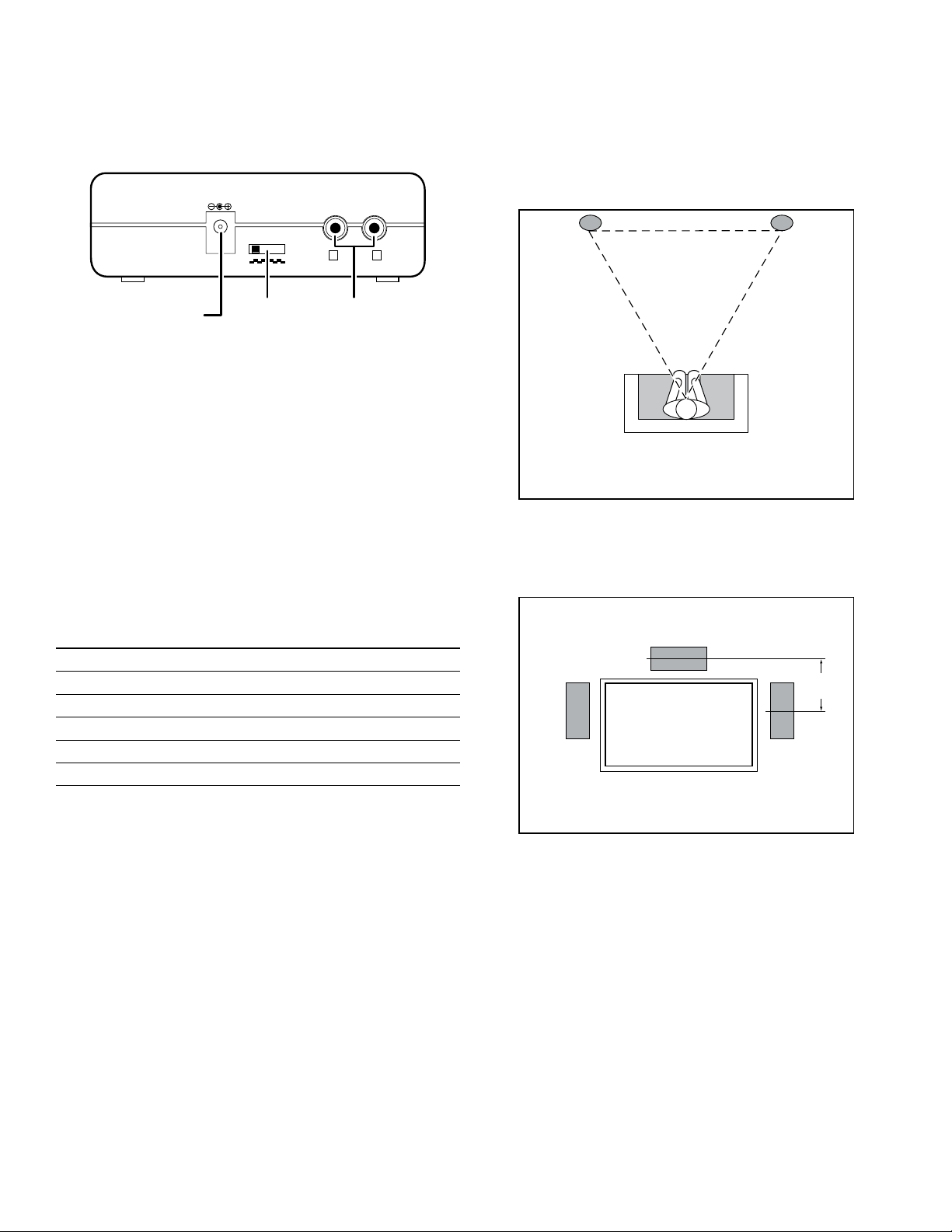
Transmitter Unit
DC 5V
WIRELESS
CODE
12
34
Power
Connector
Power connector: Plug the transmitter power supply into this connector and into a
working AC outlet.
Wireless Code switch: This switch selects between four different channels for the
wireless signal.
IMPORTANT: Be sure to set the transmitter unit’s Wireless Code switch to the same
channel that you set the subwoofer’s Wireless Code switch. See Wireless Code Settings,
on page 10, for more information.
Input connectors: Connect the supplied LFE cable from your receiver’s or processor’s
subwoofer output to either of the transmitter unit’s Input connectors.
Wireless
Code
Switch
INPUT
R
Input
Connectors
L
Color-Coding System
The HKTS 35 system uses the channel color-coding system established by the CEA to
make setting up your home theater speaker system as easy as possible. The system
includes speaker wires and an LFE cable with color bands on each end.
Speaker Placement
Front speakers
Front Left
Speaker
Place the front speakers the same distance from each other as they are from the listener’s
position. Place them at about the same height from the oor as the listener’s ears will be.
Angling them towards the listener can improve the stereo imaging.
Center Speaker
Front Right
Speaker
Speaker Position Wire Color Bands
Front Left White
Front Right Red
Center Green
Surround Left Blue
Surround Right Gray
Subwoofer Purple
Center Speaker
0 – 2 ft
(0 – 61cm)
Front Left
Speaker
Place the center speaker directly above or below the center of your TV screen. Its center
should be no more than two feet (61cm) above or below the centers of the front left and
front right speakers. If your TV set is deep enough, it may be convenient to set the center
speaker on top of the television set.
Front Right
Speaker
4
 Loading...