


HKTS 20
harman/kardon Service Manual
HKTS 20/230,
HKTS 30/230 – HKTS 30/WQ
HKTS 60/230.
Surround loudspeaker systems wit h active subwoofer.
Earlier version s with HKTS 200 SUB.
Later versions with HKTS 210 SUB.
Released EU2011 Harman Consumer Group, Inc. Rev 2, 11/2011
8500 Balboa Boulevard
Northridge, California 91329
CONTENTS
HKTS 20+30 USER GUIDE 2
HKTS 60 with 200 SUB USER GUIDE 13
HKTS 60 with 210 SUB USER GUIDE 24
HKTS 20 SAT EXPLODED VIEW/PARTS 36
HKTS 30 SAT EXPLODED VIEW/PARTS 37
HKTS 30WQ SAT EXPLODED VIEW 38
HKTS 20+30 CENTER EXPLODED VIEW 39
HKTS 20+30WQ CENTER EXPL VIEW 40
HKTS 200 SUB EXPLODED VIEW/PARTS 41
HKTS 200 PART S LIST 42
HKTS 200 SCHEMATIC DIAGRAM 43
HKTS 210 SUB EXPLODED VIEW/PARTS 44
HKTS 210 PART S LIST 45
HKTS 210 SCHEMATIC DIAGRAMS 46

HKTS 20/HKTS 30
Designed to Entertain.
™
User Guide
English
Home Theater Speaker System
harman/kardon
HKTS 20/30/60 -230V Service Manual
Page 2 of 48
ENGLISH
Introduction
Thank you for purchasing the Harman Kardon
®
HKTS20/HKTS30 speaker system, with
which you’re about to begin many years of listening enjoyment. The HKTS20/HKTS30 has
been custom designed to provide all the excitement and power of the cinema experience
in your own living room.
While sophisticated electronics and state-of-the-art speaker components are hard at work
within the HKTS20 and HKTS30, hookup and operation are simple. Color-keyed cables and
connections, and simple controls make the HKTS20/HKTS30 easy to use.
To obtain maximum enjoyment from your new home theater speaker system, we urge
you to take a few minutes to read through this manual. This will help ensure that the
connections you make to your receiver (or preamp/processor), amplifier and other devices
are correct. In addition, a few minutes spent learning the functions of the various controls
will enable you to take advantage of all the power and refinement the HKTS20/HKTS30 is
able to deliver.
If you have any questions about this product, its installation or its operation, please
contact your dealer, the best local source of information.
Description and Features
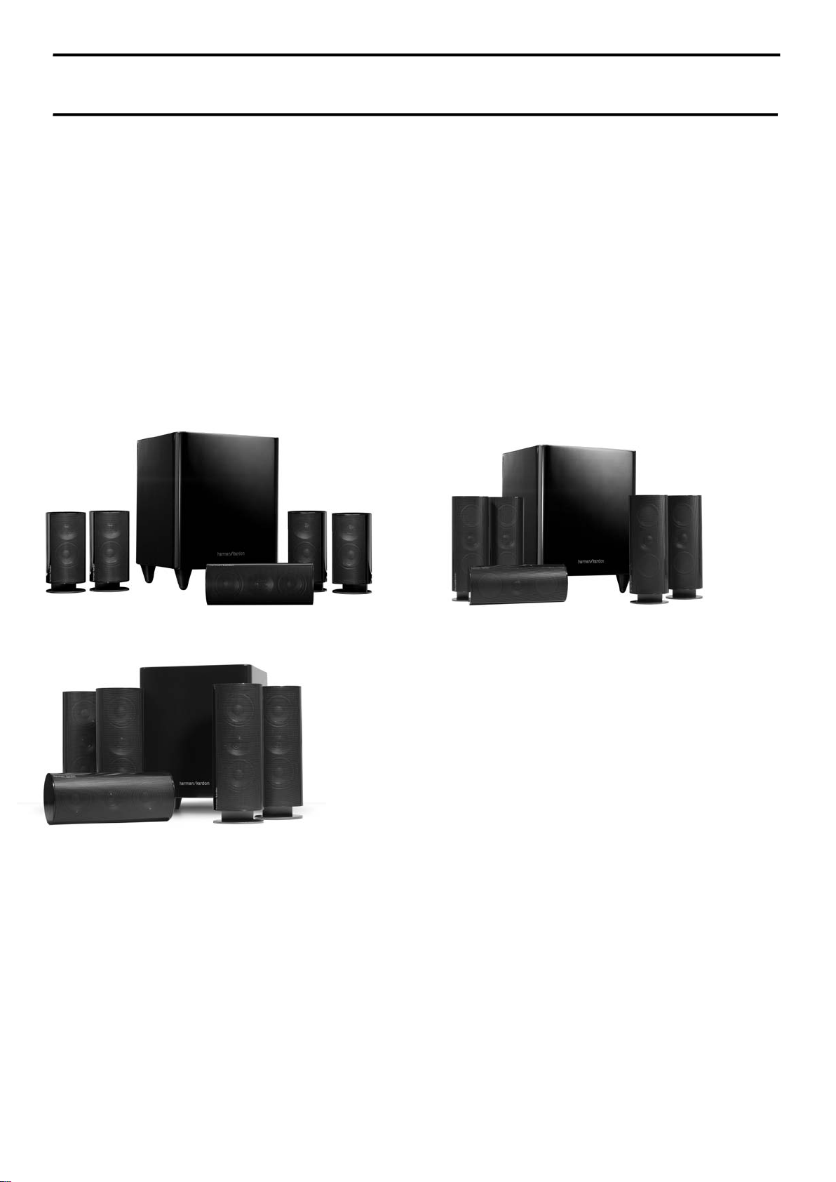
The HKTS20/HKTS30 is a complete six-piece home theater speaker system that includes:
An 8-inch, 200-watt powered subwoofer
•
Four identical two-way video-shielded satellite speakers (the HKTS30 satellite
•
speakers feature dual drivers) for the left and right front, and left and right rear
(surround) speaker positions
A dedicated, voice-matched, video-shielded, dual-driver center speaker
•
Removable bases and wall-mount brackets for the satellite speakers and a wall-
•
mount bracket for the center speaker
All of the cables you need to connect all of the speakers to your receiver or preamp/
•
processor and amplifier.
The speaker cables all use a color-coding system to conform to the Consumer Electronics
Association (CEA) standard. This color-coding system minimizes confusion when
connecting the speakers, especially when you are connecting them to a Harman Kardon
receiver.
The HKTS200SUB subwoofer is equipped with a special LFE input that simplifies
connection to receivers and preamp/processors with dedicated subwoofer outputs that
carry low-frequency signals. Other conveniences include a level control, a phase switch for
fine-tuning bass response to suit your listening environment and taste, and an efficient
switching system that senses the presence of an audio signal and automatically switches
the subwoofer from standby mode to on.
Wall-mount brackets are included for the satellite and center speakers, and shelf stands
are included for the satellite speakers. Optional HKFS3 floorstands are available separately
from your Harman Kardon dealer. Harman Kardon invented the high-fidelity receiver fifty
years ago. With state-of-the-art features and time-honored circuit designs, the HKTS20/
HKTS30 is a perfect complement to a Harman Kardon receiver, or any home theater
system.
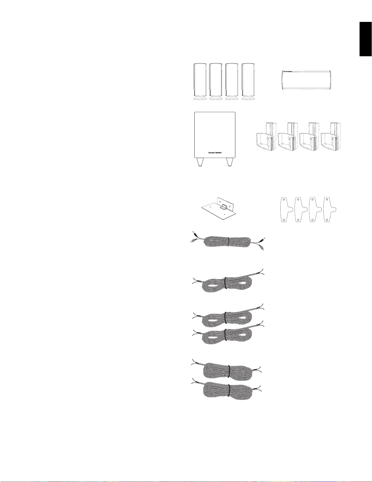
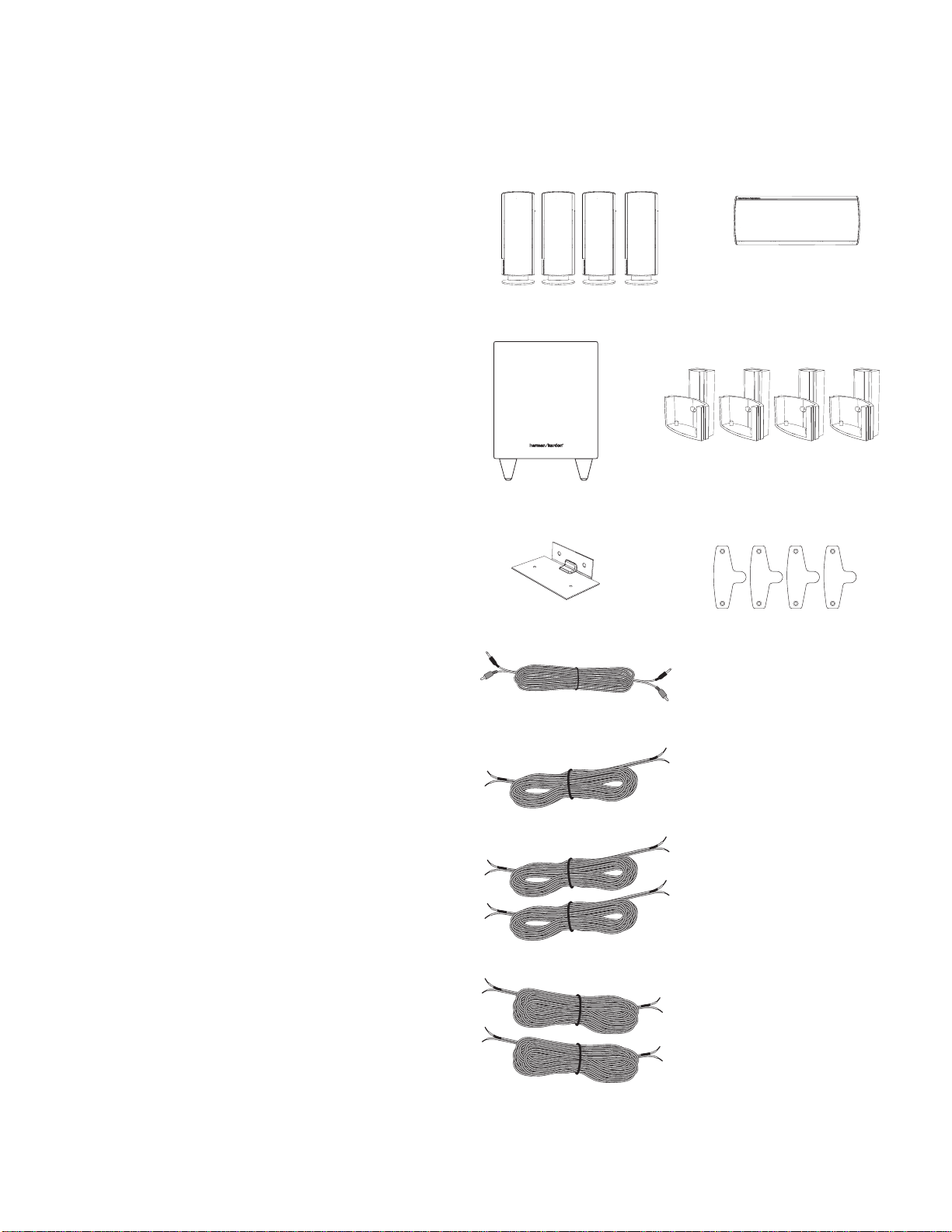
Four satellite speakers for front left/right and surround left/right
(HKTS30 satellites shown)
One powered subwoofer
Four wall-mount brackets for satellite
speakers
One wall-mount bracket for
center speaker
Four metal stop plates and screws
(for satellite speaker wall-mount brackets)
One combination LFE and trigger cable for
connection to the subwoofer
(LFE cable has purple connectors)
One 4-meter (13.1-foot) speaker cable for
center speaker (green color bands)
Two 5-meter (16.4-foot) speaker cables for
front satellites (red and white color bands)
Two 10-meter (32.8-foot) speaker cables for
rear satellites
(gray and blue color bands)
Harman Kardon®
HKTS 20 / HKTS 30
Included
harman/kardon
HKTS 20/30/60 -230V Service Manual
Page 3 of 48
PL0004-01001
1
2
3
4
5
8
9
6
7
4
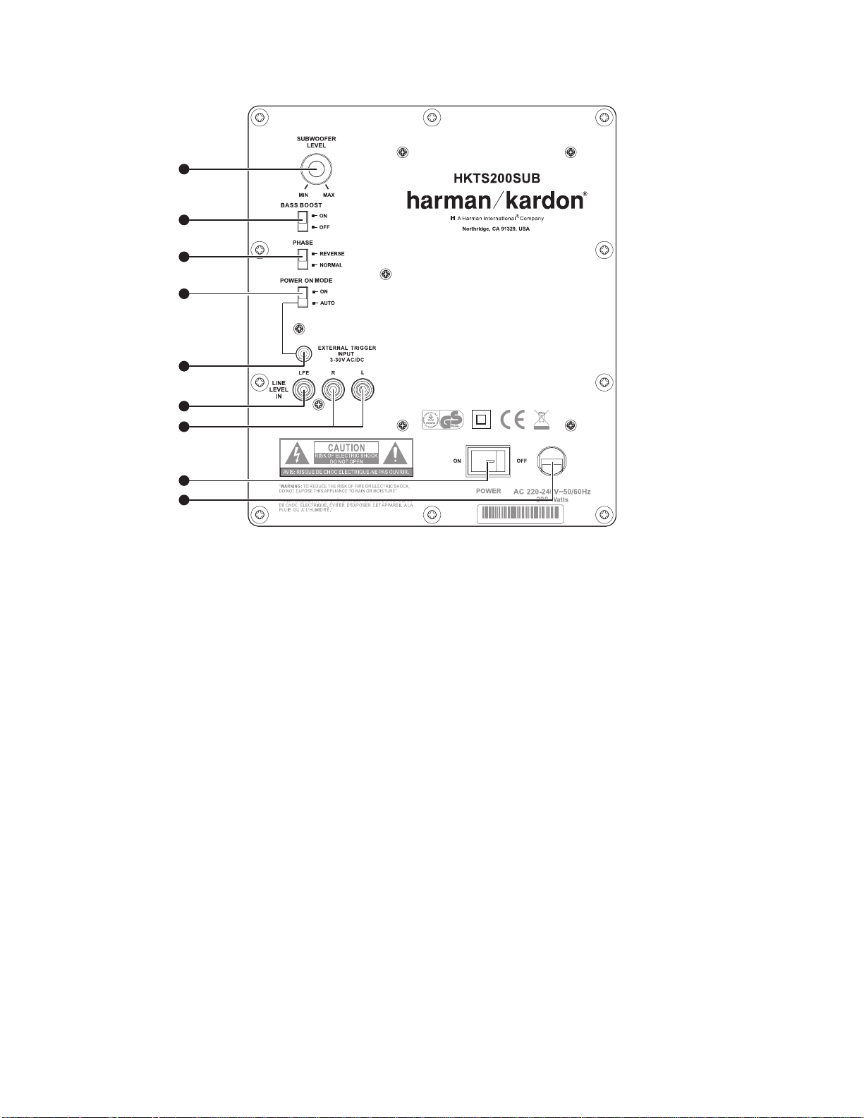
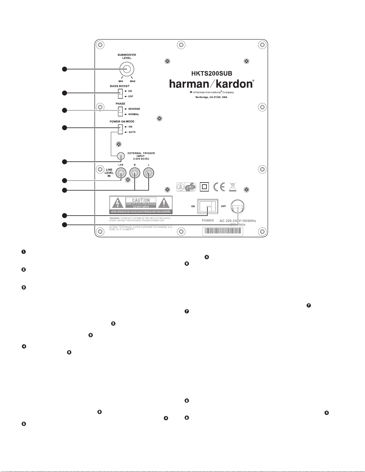
HKTS200SUB Rear-Panel Connections
Subwoofer Level Control:
.
Use this control to adjust the HKTS200SUB’s volume. Turn
clockwise to increase the volume; turn counterclockwise to decrease the volume.
Bass Boost Switch:
1.
Set this switch to ON to enhance the HKTS200SUB’s low-frequency
performance. Set this switch to OFF for normal low-frequency performance.
Phase Switch:
2.
The Phase Switch
2
determines whether the HKTS200SUB’s piston-like
action moves in and out in phase with the satellite speakers. If the subwoofer were
to play out of phase with the satellite speakers, the sound waves produced by the
subwoofer could be canceled out, reducing bass performance and sonic impact. This
phenomenon depends in part on the relative placement of all the speakers in the
room. In most cases the Phase Switch
2
should be left in the NORMAL position.
However, it does no harm to experiment, and you can leave the Phase Switch
2
in
the position that maximizes bass response and impact.
Power On Mode Switch:
3.
When set in the AUTO position and when the Power Switch
7
is set to ON, the HKTS200SUB will automatically turn itself on when it receives an
audio signal, and will enter the standby mode once no audio signal has been received
for about 15 minutes. When this switch is set in the ON position, the HKTS200SUB
will remain on whether or not it is receiving an audio signal.
An LED on the HKTS200SUB’s top panel indicates whether the subwoofer is in the on
or standby state:
• When the LED is illuminated white, the HKTS200SUB is turned on.
• When the LED is not illuminated, the HKTS200SUB is in standby mode.
When the Master Power Switch
7
is set to OFF, the LED will not be
illuminated, no matter what setting the Power On Mode Switch
3
is in.
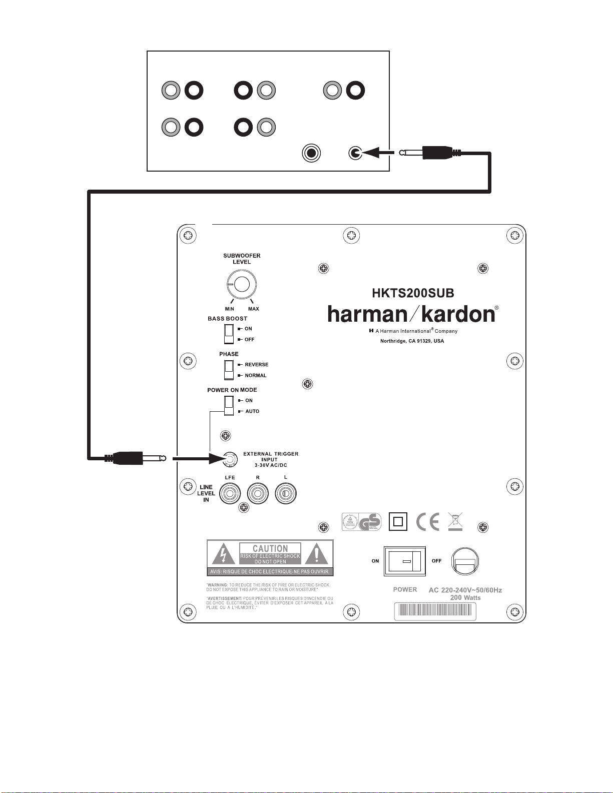
External Trigger Input:
4.
Use the mini-plug of the supplied combination LFE and trigger
cable to connect the External Trigger Input to the trigger output of another
compatible component. Whenever a trigger signal between 3 and 30V (AC or DC) is
detected, the HKTS200SUB’s amplifier will turn on. The HKTS200SUB’s amplifier will
turn off after the trigger signal ceases. (This will occur even when the Power On
Mode Switch
3
is in the AUTO position.)
Line-Level LFE In Connector:
5.
Use the LFE (purple) connector of the supplied combination
LFE and trigger cable to connect the Line-Level LFE In to the dedicated subwoofer
output of a receiver or preamp/processor. This input bypasses the HKTS200SUB’s
internal crossover circuitry, so it should only be used with a subwoofer output that has
been low-pass filtered. If your receiver or preamp/processor does not have a dedicated
subwoofer output that is low-pass filtered you should use the HKTS200SUB’s Line-
Level L/R In Connectors
6
instead.
Line-Level L/R In Connectors:
6.
Use these connectors if your receiver or preamp/processor
does not have digital surround sound decoding or a subwoofer output that is low-pass
filtered.
• If your receiver or preamp/processor has a separate subwoofer output, use the LFE
(purple) connec tor of the supplied combination LFE and trigger cable to connect it to
either one of the HKTS200SUB’s Line-Level L/R In Connectors.
• If your receiver or preamp/processor does not have a separate subwoofer output,
use two Y-adapters (not supplied). Connect an adapter’s single end to the unit’s
preamp output for that channel. Connect one of the adapter’s dual ends to the main
amp input for that channel, and connect the adapter’s other dual end to one of the
HKTS200SUB’s Line-Level L/R In Connectors. Repeat with the other Y-adapter,
preamp channel, main amp input and HKTS200SUB Line-Level L/R In Connector.
Power Switch:
7.
Set this switch in the ON position to turn the HKTS200SUB on. The
subwoofer will then either be on or in standby mode, depending on the setting of the
Power On Mode Switch
3
.
Power Cord (Non-Detachable):
8.
After you have made and verified all subwoofer
and speaker connections described in this manual, plug this cord into an active,
unswitched electrical outlet for proper operation of the HKTS200SUB. DO NOT plug this
cord into the accessory outlets found in some audio components.
harman/kardon
HKTS 20/30/60 -230V Service Manual
Page 4 of 48
ENG LIS H
Speaker Placement
NOTE: The following speaker placement, mounting and connection instructions are
identical for the HKTS20 and HKTS30 systems.
Color-Coding System
The HKTS20 and HKTS30 use the channel color-coding system established by the CEA
to make setting up your home theater speaker system as easy as possible. The HKTS20/
HKTS30 systems include speaker wires with color bands on each end.
Speaker Position Wire Color Band
Front Left White
Front Right Red
Center Green
Surround Left Blue
Surround Right Gray
Subwoofer Purple
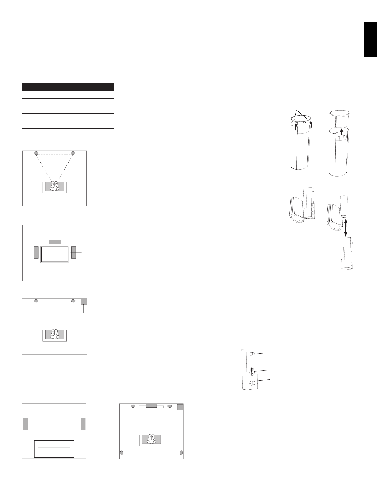
Placing the Front Speakers
The front speakers should be placed the same
distance from each other as they are from the
listening position. They should be placed at about
the same height from the floor as the listener’s
ears will be. They also can be angled toward the
listener.
Left Front
Speaker
Right Front
Speaker
Placing the Center Speaker
The center speaker should be placed slightly
behind (farther away from the listener) the front
left and right speakers. Its center should be no
more than 2 feet (61cm) above or below the
tweeters of the front left and right speakers. If you
have a CRT television, it may be convenient to set
the center speaker on top of the television set.
0 – 2ft
Center
Speaker
Left Front
Speaker
Right Front
Speaker
0 - 2 ft
(0 - 61cm)
Placing the Subwoofer
Since our ears do not hear directional sound
at the low frequencies where the subwoofer
operates, it will have good performance from
just about any location in your room. However,
the best bass reproduction is likely to be heard
when the subwoofer is placed in a corner along
the same wall as the front left and right speakers.
You can experiment with subwoofer placment
by temporarily placing it in the listening position
and playing music with strong bass content. Move
around to various locations in the room while
the system is playing and listen until you find the
location where the bass performance is best. Place
the subwoofer in that location.
Left Front
Speaker
Right Front
Speaker
Subwoofer
Placing the Surround Speakers
Left Surround
Sound
Right Surround
Sound
5 - 6 ft
(1.5m - 1.8m)
Left Front
Speaker
Right Front
Speaker
Subwoofer
Left Surround
Sound
Right Surround
Sound
The two surround speakers should be placed slightly behind the listening position, facing
each other and, ideally, should be 5–6 feet (1.5m–1.8m) from the floor. An alternate
location would be on a wall behind the listening position, facing forward. The surround
speakers should not call attention to themselves while they’re playing.
Experiment with their placement until you hear a diffuse, ambient sound accompanying
the program material heard from the front left and right and center speakers.
Mounting Options for Satellite and Center
Speakers
Shelf Placement
You can place the satellite and center speakers
on shelves. The satellite speakers have built-in
bases for shelf placement. You can also remove
the bases if desired.
To remove a satellite speaker’s base, pull
it straight off the speaker, as shown in the
illustration. Applying even pressure to both sides
of the base will allow it to slide off smoothly.
Wall-Mounting: Satellite Speakers
IMPORTANT: Read the Speaker Connec tions
section, on page 7, before wall-mounting the
satellite speakers. You will need to insert the
speaker wires through the wall mounts and
connect the wires to the speakers during the
process of installing the wall-mounts.
NOTE: If you are using your own speaker wire, it must
be no thicker than the wire supplied with the speakers. Thicker
wire will prevent the wall-mount bracket from sliding onto the
speaker.
Decide on the location for the speaker 1.
(see Speaker Placement, opposite).
Remove the speaker’s base as explained in 2. Shelf Placement, above.
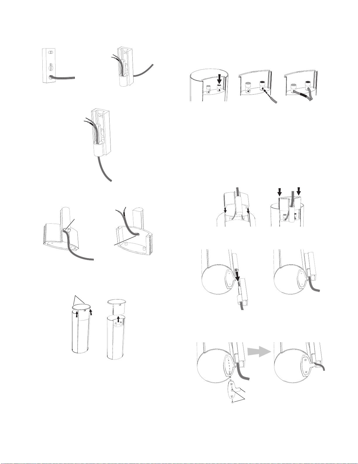
Disassemble the wall-mount bracket by sliding the two sections apart, as shown in the 3.
illustration.
Attach the wall portion of the wall-mount onto the wall using hardware that is 4.
appropriate for the wall’s construction and materials. We recommend first anchoring
the mount using its keyhole, then attaching it with another anchor through its top
opening, as shown in the illustration. Note that the satellite speakers weigh 3.3 lb
(1.5kg). Be sure to use hardware that can support this weight.
Top Opening
Keyhole Opening
Bottom Opening
Apply Pressure Evenly
to Both Sides of Base
Lift Base Straight
off Speaker
Pull Sections
Apart
Center
Speaker
harman/kardon
HKTS 20/30/60 -230V Service Manual
Page 5 of 48
6
NOTE: If you’re running the speaker wire through the wall you can bring it out directly
behind the bracket location and insert it through the bottom opening in the wall portion
of the wall-mount, as shown in the illustration. This will keep the wire completely hidden
from view once the installation is complete.
Insert Wire into
Bottom Opening
Bring Wire Out
through Here
If you’re not running the speaker wire through the wall, insert it through the wall portion
5.
of the wall-mount bracket as shown in the illustration.
Pass the speaker wire through the speaker portion of the wall-mount as shown in the 6.
illustration.
Bring Wire In
through Here
Bring Wire Out
through Here
If you have not already removed the speaker’s base, do so by pulling it straight off the 7.
speaker, as shown in the illustration. Applying even pressure to both sides of the base
will allow it to slide off smoothly.
Apply Pressure Evenly
to Both Sides of Base
Lift Base Straight
off Speaker
CAUTION: Before making speaker connections, be sure that your receiver or amplifier
is turned OFF and preferably, its AC cord is unplugged from the AC outlet.
Connect the speaker wire to the speaker terminals as shown in the illustration: 8.
Press down on the top of the terminal to open the connection hole.a)
Insert the wire’s bare end all the way into the hole.b)
Release the terminal to secure the wire. c)
Insert the conductor with the colored band into the speaker’s red ( + ) terminal, and
insert the other conductor into the speaker’s black ( – ) terminal.
+
–
A. Push Down on Cap to
Open Hole
B. Insert Bare Wire into
Open Hole
C. Release Cap to Secure Wire
IMPORTANT
:
Make sure the ( + ) and ( – ) bare wires do not touch each other or the
other terminal. Touching wires can cause a short circuit that can damage your receiver
or amplifier.
Slide the speaker portion of wall-mount onto the speaker as shown in the illustration. Fit
9.
the grooves on the mount onto the rails in the speaker, and apply even pressure on
both sides of the mount so it slides straight onto the speaker.
• Push the mount all the way onto the speaker until it snaps into place.
• Pull any slack speaker wire back through the mount as you slide the mount onto the
speaker.
Fit Bracket Grooves
onto Speaker Rails
Push Down Evenly on Both Sides of Bracket
Slide the speaker onto the mount’s wall section as shown in the illustration. Pull any slack
10.
speaker wire back through the mount’s wall section.
Slide Speaker
onto Wall-Mount
Fit the metal stop plate into the recess on the bottom of the mount with the pad facing 11.
the mount, and fasten it to the mount using two of the supplied screws. This will
prevent The speaker from detaching from the bracket and will hold the speaker’s
position as you rotate it on the mount.
Supplied Screws
Stop Plate
harman/kardon
HKTS 20/30/60 -230V Service Manual
Page 6 of 48
ENGLISH
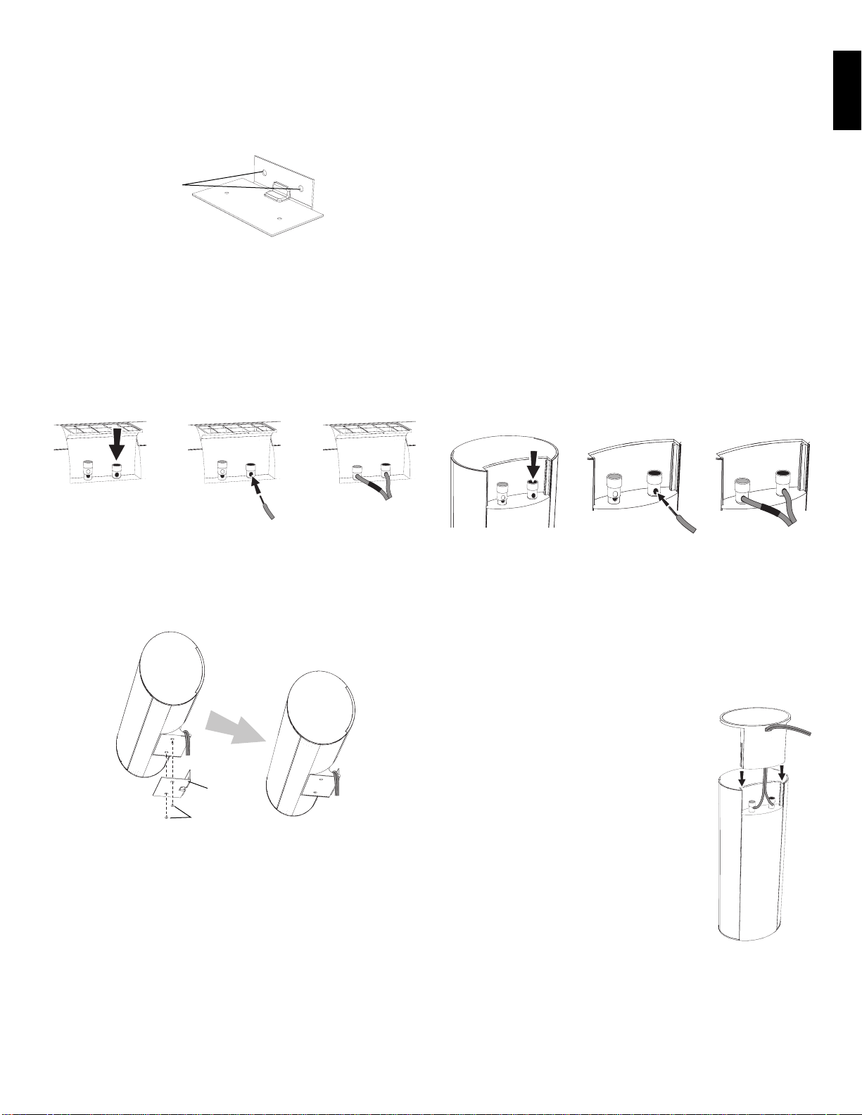
Wall-Mounting: Center Speaker
Decide on the location for the speaker (see 1. Speaker Placement, on page 5).
Attach the center speaker wall-mount bracket to the wall using hardware that is 2.
appropriate for the wall’s construction and materials. Attach the anchors through the
holes shown in the illustration.
Use These Holes
to Attach Bracket
to Wall
NOTE: The center speaker weighs 3.2 lb (1.45kg). Be sure to use hardware that can
support this weight.
CAUTION: Before making speaker connections, be sure that your receiver or amplifier is
turned OFF and preferably, its AC cord is unplugged from the AC power source.
Connect the speaker wire to the speaker terminals. Press down on the top of the terminal
3.
to open the connection hole, insert the wire’s bare end all the way into the hole and
release the terminal to secure the wire. Insert the conductor with the colored band
into the speaker’s red ( + ) terminal, and insert the other conductor into the speaker’s
black ( – ) terminal, as shown in the illustration.
+
–
A. Push Down on Cap to
Open Hole
B. Insert Bare Wire into
Open Hole
C. Release Cap to Secure Wire
IMPORTANT: Make sure the ( + ) and ( – ) bare wires do not touch each other or the
other terminal. Touching wires can cause a short circuit that can damage your receiv
er or amplifier.
Using two of the supplied screws, attach the center speaker to the wall-mount 4.
bracket, as shown in the illustration.
Supplied Screws
Wall-Mount
Bracket
Speaker Connections
CAUTION: Before making speaker connections, be sure that your receiver or amplifier is
turned OFF and preferably, its AC cord is unplugged from the AC power outlet.
Speakers and receivers/amplifiers have corresponding ( + ) and ( – ) connection
terminals. Most electronics manufacturers, including Harman Kardon, use red to denote
the ( + ) terminal and black for the ( – ) terminal. Newer Harman Kardon receivers
conform to the CEA standard and therefore use a color other than red to denote the ( + )
terminal for some speaker positions. See the table in Color-Coding System, on page 5.
Each speaker wire included with your system has colored bands at both ends of the ( + )
conductor, and the subwoofer cable has purple connectors that correspond to the color of
the HKTS200SUB’s LFE jack. This system helps ensure that the speaker in each location is
connected to the correct receiver or amplifier terminals. In addition to the colored bands
at each end, each speaker wire’s ( + ) terminal has ribs molded into its insulation to help
identify it.
It is very important to connect each speaker identically: ( + ) on the speaker to ( + ) on
the receiver or amplifier, and ( – ) on the speaker to ( – ) on the receiver or amplifier.
Miswiring one or more speakers results in thin sound, weak ba ss and a poor stereo
image. With the advent of multichannel surround-sound systems, connecting all of the
speakers in your system correctly is very important to achieving the proper ambience and
directionality of the program material.
To connect the speaker wire to the terminals on the satellite and center speakers, press
down on the top of the terminal to open the connection hole, insert the wire’s bare end
all the way into the hole and release the terminal to secure the wire. Insert the conductor
with the colored band into the speaker’s re d ( + ) terminal, and insert the other conductor
into the speaker’s black ( – ) terminal, as shown in the illustration.
+
–
A. Push Down on Cap to
Open Hole
B. Insert Bare Wire into
Open Hole
C. Release Cap to Secure Wire
IMPORTANT: Make sure the ( + ) and ( – ) bare wires do not touch each other or the
other terminal. Touching wires can cause a short circuit that can damage your receiver or
amplifier.
Connecting Satellite Speakers With Supplied
Wall-Mount Brackets
Follow the instructions in Wall-Mounting: Satellite Speakers, on page 5, and
Wall-Mounting: Center Speaker, opposite.
Connecting Satellite Speakers with Supplied Bases
Remove the speaker’s base (see1. Shelf Placement, on page 5).
Pass the speaker wire through the opening in the speaker base.2.
Connect the speaker wire as described above.3.
Reattach the speaker’s base as shown in the illustration.4.
harman/kardon
HKTS 20/30/60 -230V Service Manual
Page 7 of 48
PL0004-01001
+–
+– +–
+–+–
LEFT
SUB
LFE OUT
+ – + –
+ –
+ –
+ –
+ –
+ –
RIGHT
SURROUNDFRONT CENTER
8
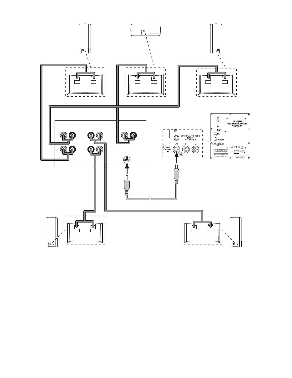
Use this installation method for receivers and preamp/processors that have a dedicated
subwoofer output with low-pass filtering (also called bass management). If the dedicated
subwoofer output does not have low-pass filtering, follow the instructions in Connecting
the Subwoofer to a Receiver or Preamp/Processor With Line Outputs, on page 9.
Use the LFE (purple ) connector of the supplied comb ination LFE and trigger cable to
connect the HKTS200SUB’s Line-Level LFE In Jack
5
to the dedicated subwoofer output
(or LFE output) of your receiver or preamp/processor.
Connect each satellite speaker and the center speaker to the corresponding speaker
terminals on your receiver or amplifier.
In your receiver or preamp/processor’s setup menu, configure it for Subwoofer ON, and
set the front left, front right, center, and surround speakers to Small. After you have made
and verified all connections, plug the HKTS200SUB’s AC Power Cord
8
into an active AC
outlet.
Connecting the Subwoofer to a Receiver or Preamp/Processor With a Dedicated Subwoofer Output
Left Front
Receiver
Left
Surround
Right
Surround
Subwoofer
Center Right Front
Front Left
Speaker Cable
(White Bands)
LFE/Trigger Cable
(Purple Ends)
Surround Right
Speaker Cable
(Gray Bands)
Surround Left
Speaker Cable
(Blue Bands)
Center
Speaker Cable
(Green Bands)
Front Right
Speaker Cable
(Red Bands)
harman/kardon
HKTS 20/30/60 -230V Service Manual
Page 8 of 48
PL0004-01001
+–
+– +–
+–+–
LEFT
LINE-LEVEL
OUTPUTS
L R
+ – + –
+ –
+ –
+ –
+ –
+ –
RIGHT
SURROUNDFRONT CENTER
ENGLISH
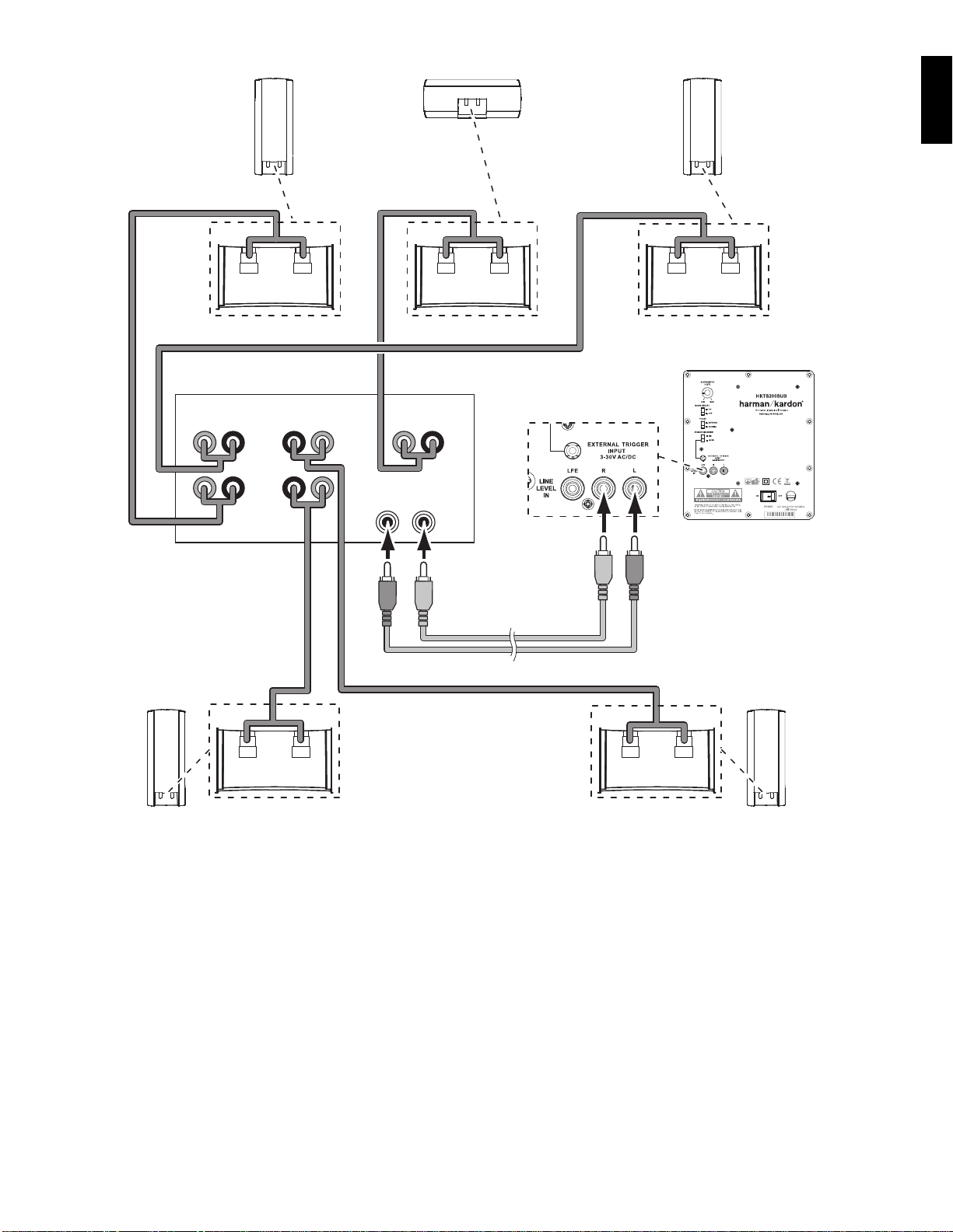
Use this installation method for receivers and preamp/processors that do not have a
dedicated subwoofer output, but do have preamp-level (volume-controlled) line outputs.
If the receiver or preamp/processor has a dedicated subwoofer output with low-pass
filtering, see Connecting the Subwoofer to a Receiver or Preamp/Processor With a D edicated
Subwoofer Output, on page 8.
If you’re connec ting to a receiver with left and right line outputs that are not connected to
amplifier inputs, connect the LFE (purple) connector of the supplied combination LFE and
trigger cable to one of those outputs and to either of the HKTS200SUB’s Line -Level L/R
In Connectors
6
. Use a second RCA cable (not supplied) to connect the other receiver or
preamp line output to the other of the HKTS200SUB’s Line -Level L/R In Connectors
6
.
If you’re connec ting to a receiver or preamp/processor with left and right line outputs
that are connected to amplifier front left and right inputs, connect the single ends of
Y-adapters (not supplied) to the receiver’s or processor’s left and right line outputs.
Connect one of the Y-adapter’s double ends to the HKTS200SUB’s Line-Level L/R In
Connectors
6
, and connect the other double end to your amplifier’s front left and right
inputs.
Connect each satellite speaker and the center speaker to the corresponding speaker
terminals on your receiver or amplifier.
In your receiver or preamp/processor’s setup menu, configure it for Subwoofer ON, and set
the front left, front right, center, and surround speakers to Small.
After you have made and verified all connections, plug the HKTS200SUB’s AC Power Cord
8
into an active AC outlet.
Connecting the Subwoofer to a Receiver or Preamp/Processor With Line Outputs
Left Front
Receiver
Left
Surround
Right
Surround
Subwoofer
Center Right Front
Front Left
Speaker Cable
(White Bands)
Surround Right
Speaker Cable
(Gray Bands)
Surround Left
Speaker Cable
(Blue Bands)
RCA Cable
(Not Supplied)
(Red and White Ends)
Center
Speaker Cable
(Green Bands)
Front Right
Speaker Cable
(Red Bands)
harman/kardon
HKTS 20/30/60 -230V Service Manual
Page 9 of 48
PL0004-01001
LEFT
LFE SUB
OUTPUT
12V
TRIGGER
OUTPUT
+ – + –
+ –
+ –
+ –
+ –
+ –
RIGHT
SURROUNDFRONT CENTER
10
If your preamp/processor or another audio/video component has a trigger voltage
connection that supplies between 3 and 30V (AC or DC), connect it to the HKTS200SUB’s
External Trigger Input Connector
4
. If the component’s trigger voltage connection has
a 3.5mm mini jack you can use the supplied combination LFE/trigger cable to make the
connection.
Connecting to a Trigger Voltage Source
Receiver
Subwoofer
Trigger Cable
(Black Ends)
harman/kardon
HKTS 20/30/60 -230V Service Manual
Page 10 of 48

ENGLISH
TroubleshootingOperation
If there is no sound from any of the speakers:
Check that the receiver/amplifier is on and a source is playing.
•
Make sure that all wires and connections between the receiver/amplifier and the
•
speakers are connected properly.
Make sure none of the speaker wires is frayed, cut or punctured.
•
Review the proper operation of your receiver/amplifier.
•
If there is no sound coming from one speaker:
Check that the bala nce control on your receiver/amplifier is not s et all the way to
•
one channel.
Check your receiver/amplifier’s speaker setup procedure to make sure that he
•
speaker in question has been enabled and its volume level has not been turned all
the way down.
Make sure that all wires and connections between the receiver/amplifier and the
•
speaker are connected properly.
Make sure the speaker wires are not frayed, cut or punctured.
•
If there is no sound coming from the center speaker:
Check your receiver/amplifier’s speaker setup procedure to make sure that the
•
center speaker has been enabled and its volume level has not been turned all the
way down.
Make sure that all wires and connections between the receiver/amplifier and the
•
center speaker are connected properly.
Make sure the speaker wires are not frayed, cut or punctured.
•
If your receiver is operating in Dolby® Pro Logic® mode, make sure that the center
•
speaker is not set to Phantom.
If there is no sound coming from the surround speakers:
Check your receiver/amplifier’s speaker setup procedure to make sure that the
•
surround speakers have been enabled and their volume levels have not been
turned all the way down.
Make sure that all wires and connections between the receiver/amplifier and the
•
surround speakers are connected properly.
Make sure the speaker wires are not frayed, cut or punctured.
•
Review proper operation of your receiver/processor and its surroundsound features.
•
Make sure the movie or TV show you’re watching has been recorded in a surround-
•
sound mode. If it is not, check to see if your receiver/amplifier has a different
surround-sound mode that you can use.
Review the operation of your DVD player and the DVD jacket to make sure the DVD
•
features the desired Dolby Digital or DTS® surround-sound mode, and that you
have properly selected that mode using both the DVD player’s menu and the disc’s
menu.
If there is no sound coming from the subwoofer:
Check that the subwoofer’s
•
Power Cord
8
is plugged into a working AC outlet.
Check that the subwoofer’s
•
Power Switch
7
is in the ON position.
Check that the
•
Subwoofer Level Control
is not turned all the way down (fully
counterclockwise).
Check the audio connection between your receiver/processor and the subwoofer.
•
Check your receiver/amplifier’s speaker setup procedure to make sure that the
•
subwoofer has been enabled and its volume level has not been turned all the way
down.
If the system plays at low volumes but shuts off as volume is increased:
Make sure that all wires and connections between the receiver/amplifier and the
•
speakers are connected properly.
Make sure none of the speaker wires is frayed, cut or punctured.
•
If you’re using more than one pair of main speakers, check to be sure that you’re
•
not operating the system below the receiver/amplifier’s minimum impedance
requirements.
Turning the Subwoofer On and Off
Set the HKTS200SUB’s Power Switch
7
to the ON position.
If the
•
Power On Mode Switch
3
is set to AUTO, the HKTS200SUB will
automatically turn i tself on when it receives an audio sig nal, and it will go into
standby mode when it has received no audio signal for 15 minutes. The HKTS200
SUB’s LED will illuminate white when the subwoofer is on, and will not be illuminated
when the subwoofer is in standby.
If the
•
Power On Mode Switch
3
is set to ON, the HKTS200SUB will remain on at all
times. The HKTS200 SUB’s LED will illuminate white.
If the
•
External Trigger Input Connector
4
is connected to a trigger voltage source,
the HKTS200SUB will turn on whenever a trigger voltage is present, and will turn off
after the trigger voltage ceases, regardless of the position of the Power On Mode
Switch
3
.
If you will be away from home for an extended period of time, or if you will not be
using the subwoofer for an extended period, switch the Power Switch
7
to the OFF
Position.
Subwoofer Adjustments: Volume
Use the Subwoofer Level Control
to set the HKTS200SUB’s volume. Turn the knob
clockwise to increase the subwoofer’s volume; turn the knob counterclockwise to decrease
the subwoofer’s volume.
Subwoofer Adjustments: Phase
The Phase Switch
2
determines whether the HKTS200SUB’s piston-like action moves
in and out in phase with the satellite speakers. If the subwoofer were to play out of
phase with the satellite speakers, the sound waves produced by the subwoofer could be
canceled out, reducing bass performance and sonic impact. This phenomenon depends in
part on the relative placement of all the speakers in the room.
Although in most cases the Phase Switch
2
should be left in the NORMAL position,
there is no absolute correct setting for the Phase Switch
2
. When the HKTS200SUB
is properly in phase with the satellite speakers, the sound will be clearer and have
maximum impact. This will make percussive sounds like drums, piano and plucked strings
sound more lifelike. The best way to set the Phase Switch
2
is to listen to music that you
are familiar with and set the switch in the position that gives drums and other percussive
sounds maximum impact.
Subwoofer Adjustments: Bass Boost
When set to the ON position, the Bass Boost Switch
1
enhances low-frequency
performance, resulting in bass with more impact, which you may prefer while watching
movies or listening to music. There is no harm in experimenting with this control –
setting the switch to the OFF position will return normal low-frequency performance.
harman/kardon
HKTS 20/30/60 -230V Service Manual
Page 11 of 48

Specifications
HKTS20 System HKTS30 System
Frequency Response
45Hz – 20kHz (-6dB)
Frequency Response
45Hz – 20kHz (-6dB)
SAT-TS20 Satellites SAT-TS30 Satellites Cen-TS20/30 HKTS200SUB Subwoofer
Recommended Power
10 ~ 80 watts
Recommended Power
10 ~ 120 watts
Recommended Power
10 ~ 120 watts
Input rating:
AC 100–120V, 50/60 Hz, 200W or
AC 220–240V, 50/60 Hz, 200W
Impedance
8 ohms nominal
Impedance
8 ohms nominal
Impedance
8 ohms nominal
Amplifier Power
200 watts RMS
Sensitivity
83dB @ 2.83V/1 meter
Sensitivity
86dB @ 2.83V/1 meter
Sensitivity
86dB @ 2.83V/1 meter
Bass
8" woofer, sealed enclosure
Tweeter
One 3/4" (19mm) dome, video-shielded
Tweeter
One 3/4" (19mm) dome, video-shielded
Tweeter
One 3/4" (19mm) dome, video-shielded
External Trigger Input Voltage
3 ~ 30 volts AC/DC
Midrange
One 3" (75mm) driver, video-shielded
Midrange
Dual 3" (75mm) drivers, video-shielded
Midrange
Dual 3" (75mm) drivers, video-shielded
Dimensions – including stands (H x W x D)
8-1/2" x 4-11/32"x 3-15/32"
(216mm x 110mm x 88mm)
Dimensions – including stands (H x W x D)
11-25/32" x 4-11/32" x 3-15/32"
(299mm x 110mm x 88mm)
Dimensions (H x W x D)
4-11/32" x 10-11/32" x 3-15/32"
(110mm x 272mm x 88mm)
Dimensions (H x W x D)
13-29/32" x 10-1/2" x 10-1/2"
(353mm x 267mm x 267mm)
Weight
2.1 lb (0.95kg)
Weight
3.3 lb (1.5kg)
Weight
3.2 lb (1.45kg)
Gross Weight
19.8 lb (9kg)
Harman Consumer Group, Inc.
8500 Balboa Boulevard, Northridge, CA 91329 USA
516.255.4545 (USA only)
www.harmankardon.com
Made in China
Part No. 444020-001, 444021-001
© 2009 Harman International Industries, Incorporated. All rights reserved.
Features, specifications and appearance are subject to change without notice.
Harman Kardon is a trademark of Harman International Industries, Incorporated, registered in the United States
and/or other countries. Designed to Entertain is a trademark of Harman International Industries, Incorporated.
Dolby and Pro Logic are registered trademarks of Dolby Laboratories.
DTS is a registered trademark of Digital Theater Systems, Inc.
harman/kardon
HKTS 20/30/60 -230V Service Manual
Page 12 of 48

HKTS 60BQ/230
Home theater speaker system
User Guide
English................................
Deutsch..............................
Suomi................................
Français..............................
Italiano................................
Español...............................
Svenska..............................
.............................
Nederlands..........................
harman/kardon
HKTS 20/30/60 -230V Service Manual
Page 13 of 48
3
Introduction
Thank you for purchasing the Harman Kardon
®
HKTS60 speaker
system, with which you’re about to begin many years of listening
enjoyment. The HKTS60 has been custom designed to provide
all the excitement and power of the cinema experience in your own
living room.
While sophisticated electronics and state-of-the-art speaker components
are hard at work within the HKTS60, hookup and operation are simple.
Color-keyed cables and connections, and simple controls make
the HKTS60 easy to use.
To obtain maximum enjoyment from your new home theater speaker
system, we urge you to take a few minutes to read through this manual.
This will help ensure that the connections you make to your receiver
(or preamp/processor), amplifier and other devices are correct. In addition,
a few minutes spent learning the functions of the various controls will
enable you to take advantage of all the power and refinement the
HKTS60 is able to deliver.
If you have any questions about this product, its installation or its
operation, please contact your dealer, the best local source of information.
Description and Features
The HKTS60 is a complete six-piece home theater speaker system
that includes:
• An 8-inch, 200-watt powered subwoofer
• Four identical two-way video-shielded dual-driver satellite speakers
for the left and right front, and left and right rear (surround)
speaker positions
• A dedicated, voice-matched, video-shielded, dual-driver center speaker
• Removable bases and wall-mount brackets for the satellite speakers
and a wall-mount bracket for the center speaker
• All of the cables you need to connect all of the speakers to your receiver
or preamp/processor and amplifier.
The speaker cables all use a color-coding system to conform to the
Consumer Electronics Association (CEA) standard. This color-coding
system minimizes confusion when connecting the speakers, especially
when you are connecting them to a Harman Kardon receiver.
The HKTS200SUB subwoofer is equipped with a special LFE input that
simplifies connection to receivers and preamp/processors with dedicated
subwoofer outputs that carry low-frequency signals. Other conveniences
include a level control, a phase switch for fine-tuning bass response to
suit your listening environment and taste, and an efficient switching
system that senses the presence of an audio signal and automatically
switches the subwoofer from standby mode to on.
Wall-mount brackets are included for the satellite and center speakers,
and shelf stands are included for the satellite speakers. Optional HKFS3
floorstands are available separately from your Harman Kardon dealer.
Harman Kardon invented the high-fidelity receiver fifty years ago.
With state-of-the-art features and time-honored circuit designs,
the HKTS60 is a perfect complement to a Harman Kardon receiver,
or any home theater system.
Included
Four satellite speakers for front left/right
and surround left/right
Harman Kardon
®
HKTS 60
One powered subwoofer Four wall-mount brackets for
satellite speakers
One center speaker
One wall-mount bracket
for center speaker
Four metal stop plates and screws
(for satellite speaker wall-mount brackets)
One combination LFE and trigger cable
for connection to the subwoofer
(LFE cable has purple connectors)
One 4-meter (13.1-foot) speaker cable
for center speaker (green color bands)
Two 5-meter (16.4-foot) speaker cables
for front satellites
(red and white color bands)
Two 10-meter (32.8-foot) speaker cables
for rear satellites
(gray and blue color bands)
harman/kardon
HKTS 20/30/60 -230V Service Manual
Page 14 of 48
4
HKTS200SUB Rear-Panel Connections
PL0004-01001
1
2
3
4
5
8
9
6
7
Subwoofer Level Control: Use this control to adjust the HKTS200SUB’s
volume. Turn clockwise to increase the volume; turn counterclockwise
to decrease the volume.
Bass Boost Switch: Set this switch to ON to enhance the
HKTS200SUB’s low-frequency performance. Set this switch to OFF
for normal low-frequency performance.
Phase Switch: This determines whether the HKTS200SUB’s piston-like
action moves in and out in phase with the satellite speakers. If the
subwoofer were to play out of phase with the satellite speakers,
the sound waves produced by the subwoofer could be canceled out,
reducing bass performance and sonic impact. This phenomenon
depends in part on the relative placement of all the speakers in the
room. In most cases the Phase Switch should be left in the
NORMAL position. However, it does no harm to experiment, and you
can leave the Phase Switch in the position that maximizes bass
response and impact.
Power On Mode Switch: When set in the AUTO position and when
the Power Switch is set to ON, the HKTS200SUB will automatically
turn itself on when it receives an audio signal, and will enter the
standby mode once no audio signal has been received for about
15 minutes. When this switch is set in the ON position,
the HKTS200SUB will remain on whether or not it is receiving an
audio signal.
An LED on the HKTS200SUB’s top panel indicates whether the
subwoofer is in the on or standby state:
• When the LED is illuminated white, the HKTS200SUB is turned on.
• When the LED is not illuminated, the HKTS200SUB is in standby mode.
When the Master Power Switch is set to OFF, the LED will not be
illuminated, no matter what setting the Power On Mode Switch is in.
External Trigger Input: Use the mini-plug of the supplied combination
LFE and trigger cable to connect the External Trigger Input to the
trigger output of another compatible component. Whenever a trigger
signal between 3 and 30V (AC or DC) is detected, the HKTS200SUB’s
amplifier will turn on. The HKTS200SUB’s amplifier will turn off after
the trigger signal ceases.
(This will occur even when the Power On Mode
Switch is in the AUTO position.)
Line-Level LFE In Connector: Use the LFE (purple) connector of the
supplied combination LFE and trigger cable to connect the Line-Level
LFE In to the dedicated subwoofer output of a receiver or preamp/
processor. This input bypasses the HKTS200SUB’s internal crossover
circuitry, so it should only be used with a subwoofer output that has
been low-pass filtered. If your receiver or preamp/processor does not
have a dedicated subwoofer output that is low-pass filtered you should
use the HKTS200SUB’s Line-Level L/R In Connectors instead.
Line-Level L/R In Connectors: Use these connectors if your receiver or
preamp/processor does not have digital surround sound decoding or a
subwoofer output that is low-pass filtered.
• If your receiver or preamp/processor has a separate subwoofer
output, use the LFE (purple) connector of the supplied combination
LFE and trigger cable to connect it to either one of the HKTS200SUB’s
Line-Level L/R In Connectors.
• If your receiver or preamp/processor does not have a separate
subwoofer output, use two Y-adapters (not supplied). Connect an
adapter’s single end to the unit’s preamp output for that channel.
Connect one of the adapter’s dual ends to the main amp input for that
channel, and connect the adapter’s other dual end to one of the
HKTS200SUB’s Line-Level L/R In Connectors. Repeat with the other
Y-adapter, preamp channel, main amp input and HKTS200SUB
Line-Level L/R In Connector.
Power Switch: Set this switch in the ON position to turn the
HKTS200SUB on. The subwoofer will then either be on or in standby
mode, depending on the setting of the Power On Mode Switch .
Power Cord (Non-Detachable): After you have made and verified all
subwoofer and speaker connections described in this manual, plug this
cord into an active, unswitched electrical outlet for proper operation of
the HKTS200SUB. DO NOT plug this cord into the accessory outlets
found in some audio components.
1
2
3
3
3
4
4
4
4
6
5
8
8
7
7
8
9
harman/kardon
HKTS 20/30/60 -230V Service Manual
Page 15 of 48
 Loading...