


®
®
Power for the Digital Revolution.
HS 100
INTEGRATED HOME THEATER SYSTEM
OWNER’S MANUAL
PLAYERJPEG MP3 |
CD |
DVD-AUDIO |
5.1ch |
PROG RAND |
REP |
1 ALL |
A-B |
P.SCAN TEST |
RADIOVCD |
GROUP TITLE |
TRACK |
CHAP |
HOUR |
PBC |
|
MIN |
SEC |
AUX DVD |
|
|
|
|
|
|
|
|
DIGITAL IN |
|
|
|
|
|
|
|
|
WMA |
|
|
|
|
|
|
|
|

TABLE OF CONTENTS
3Introduction
4Safety Information
4Unpacking
5Front-Panel Controls
6Front-Panel Display
7Rear-Panel Connections
8Remote Control
Installation and Connections
10Installation and Connections
10Speaker Placement
10Main Speaker Connections
11Subwoofer Placement and Connection
11Audio Equipment Connections
11Video Equipment Connections
11System Connections
11Connecting the AC Power
System Setup
12System Setup
12System Defaults
12Setup Menu
12System Settings
12Display Language
12Preferred Subtitle Language
12Panel Time-Out
12Status Bar Time-Out
12Parental Control
13Disc Recognition
13PBC Support
13Screen Saver
13Audio Setup Menu
13Preferred Audio Language
13Dynamic Range
13Delay Unit
13Tone Control
13Bass Level
13Treble Level
13DVD Sound Mode
14Audio Adjustment
14 Delay
14Output Level Adjustment
14Video Setting
14Aspect Ratio
14Scan Type
15Video Mode
15Video Adjustments Menu
15Test Screen
15TV Picture Adjustment with Test Screen
15Brightness Adjustment
15Contrast Adjustment
16Color and Tint Adjustment
Terminology and DVD Basics
17 Terminology
17 DVD Basics
Playback Basics for All Formats
18 Loading Discs
18 Playback Features for DVD and CD Discs
Basic Operation
19 Basic Operation
19 Surround Modes
Playing DVDs and CDs
20 Using the On-Screen Status Display
20 Terminology
20 Selecting a Title
20 Selecting a Group
20 Selecting a Chapter
20 Selecting a Track
20Changing the Time Display
21Selecting or Changing Subtitles
21Selecting an Angle
21 Repeat Play
21 Information Display
DVD Playback
22 Using a DVD’s Menu
22 Important Notes on DVD Playback
22 Zoom Feature
22 Playback Resume Feature
MP3, WMA* and JPEG Playback
23 MP3, WMA and JPEG Playback
23 Slide Shows
VCD Playback
24 VCD Playback
24 Playback Control
Using the Player Menu
25 Using the Player Menu
25 Disc Info Menu
25 Programmed Playback
26 Notes on Programmed Playback
Tuner Operation
27Tuner Operation
27Entering Presets
27Selecting Presets
28RDS Information
28Surround Mode
TV Menu, AUX Menu, Digital In Menu
29 |
TV Menu |
29 |
Audio |
29 |
Level Adjustment |
29 |
AUX Menu |
29 |
Audio |
29Level Adjustment
29Digital In Menu
29Digital Input
30Audio
30 Level Adjustment
30 Surround Modes
DVD Language Codes
31 Language Codes
Troubleshooting
32 Troubleshooting
Specifications
33 Specifications
Typographical Conventions
In order to help you use this manual with the remote control, front-panel controls and rear-panel connections, certain conventions have been used.
EXAMPLE – (bold type) indicates a specific remote control or front-panel button, or rear-panel connection jack
EXAMPLE – (OCR type) indicates a message that is visible on the front-panel information display
1 – (number in a square) indicates a specific front-panel control
– (number in a circle) indicates a rear-panel connection
0 – (number in an oval) indicates a button or indicator on the remote
A – (letter in a square) indicates an indicator on the front-panel display
å – (letter in a circle) indicates a section of an on-screen display
Please register your HS 100 by visiting our Web site at www.harmankardon.com. At the same time, you may choose to be notified about our new products and special promotions. Note that you will need the serial number shown on the rear panel of your HS 100 to complete the registration process.
2 TABLE OF CONTENTS

INTRODUCTION
Thank you for choosing Harman Kardon®!
With the purchase of a Harman Kardon HS 100, you are about to begin many years of home theater enjoyment. Designed to provide the usual excitement of movies and every nuance of musical selections, the HS 100 is truly a complete home theater system for the new millennium.
The HS 100 has been engineered to make it easy to take advantage of the power of its digital technology. To obtain the maximum enjoyment from your new system, we urge you to read this manual. A few minutes spent learning the functions of the various controls
will enable you to take advantage of everything the HS 100 is able to deliver.
If you have any questions about this product, its installation or its operation, please contact your retailer or custom installer. They are your best local sources of information.
Description and Features
The HS 100 is among the most versatile home cinema systems available, incorporating an audio video controller, with built-in DVD-Audio/Video player, a powerful amplifier and a complete 5.1 loudspeaker system in one complete system solution. In addition to Dolby Digital and DTS decoding for digital sources, the Dolby Pro Logic II mode for Matrix surround-encoded or Stereo recordings is available for use with sources such as CD, VCR, TV broadcasts and the system’s own FM/AM tuner.
To enable you to get the maximum quality from DVDs, the HS 100 is equipped with the latest in design techniques, including advanced 10-bit video digital- to-analog converters (DAC) and video (composite), S-video and component video outputs, to ensure that you get all the quality inherent in today’s DVD medium. For optimum playback with compatible digital display devices, the HS 100 is equipped with progressive component video outputs.
A wide range of features makes it easy to program an evening’s entertainment. When playing DVDs, easy-to- understand on-screen menus and icons make it simple to change languages, soundtracks, subtitles or aspect ratio, while a parental-lock function enables you to control which discs may be viewed by younger members of the household.
Disc Formats Supported by This Player
The unit can play the following disc formats in both 5-inch (12cm) and 3-inch (8cm) sizes:
•DVD-Audio
•DVD
•DVD-R
•DVD-RW
•DVD+R
•DVD+RW
•CD
•CD-R
•CD-RW
•VCD
•SVCD
NOTE: Due to differences in the format of certain discs, it is possible that some discs may include a mix of features that are not compatible with the HS 100. Similarly, although the HS 100 is capable of a wide range of features, not all discs include every capability of the DVD system. For example, although the HS 100 is compatible with multi-angle discs, that feature is only possible when the disc is specially encoded for multi- ple-angle play. In addition, the HS 100 is capable of playing back both Dolby Digital and DTS soundtracks, but the number and types of tracks available will vary from disc to disc. To make certain that a specific feature or soundtrack option is available, please check the options noted on the disc jacket.
■Playback capability for CD-R, CD-RW, WMA, JPEG, MP3, VCD/SVCD, DVD-R, DVD+R, DVD-RW and DVD+RW discs may vary with the quality of the disc and the recorder used to create the disc.
1
NOTE: This player is designed and manufactured for compatibility with Region Management Information that is encoded on most DVD discs. This player is designed only for playback of discs with Region Code 1, or for discs that do not contain Region Code information. If there is any other Region Code on a disc, that disc will not play on the DVD.
Upgradeability
The “firmware” controlling the functionality of the
HS 100 is upgradeable. In the event of future improvements to its operations and features, it will be possible to use special CD-ROM discs to upgrade your system.
Features
■Plays a Wide Range of Video and Audio Formats, Including DVD-Video Discs, VCD, Standard CD Audio Discs, CD-R/RW, DVD-R/RW, DVD+R/RW, Windows Media® Discs and MP3 Discs
■DVD-Audio Playback for Expanded Dynamic Range and Improved Realism
■High-Quality Video Playback 10-Bit DACs, Progressive Scan and Component Video Outputs
■Easy-to-Use On-Screen Navigation System
■Playback of MP3 and Windows® WMA Audio Discs and JPEG Image Files
■Simultaneous Playback of MP3 and JPEG files
■Extensive Programming Capability for Audio and Video Discs
■Parental Lock Controls Prevent Unauthorized Viewing of Restricted Movies
■Multiple Options for Language, Soundtrack and Subtitle Selection
■Multiple-Angle Capabilities With Specially Encoded DVD Discs
■On-Screen Menu and Display System
IMPORTANT NOTES:
This manual should be read in conjunction with the owner’s manual of the accompanying loudspeaker system. The instructions found therein should be followed with respect to loudspeaker operation and safety.
Use the HS 100 controller only with the loudspeaker system supplied. Failure to do so may cause damage to either the controller or the loudspeakers and may invalidate the warranty.
This system was designed to provide you with many years of reliable operation with a minimum of care and maintenance. If you experience any problems with the setup or operation of this system, please review the Troubleshooting Guide at the end of this manual before you contact your authorized Harman Kardon dealer.
INTRODUCTION 3

SAFETY INFORMATION
Important Safety Information
Verify Line Voltage Before Use
Your HS 100 has been designed for use with
110 –240-volt AC current and the line cord and plug are specifically designed for 120-volt applications. Connection to a line voltage other than that for which it is intended can create a safety and fire hazard and may damage the unit.
If you have any questions about the voltage requirements for your specific model, or about the line voltage in your area, contact your selling dealer before plugging the unit into a wall outlet.
Do Not Use Extension Cords
We do not recommend that extension cords be used with this product. As with all electrical devices, do not run power cords under rugs or carpets or place heavy objects on them. Damaged power cords should be replaced immediately by an authorized service center with cords meeting factory specifications.
Handle the AC Power Cord Gently
When disconnecting the power cord from an AC outlet, always pull the plug; never pull the cord. If you do not intend to use the unit for any considerable length of time, disconnect the plug from the AC outlet.
Do Not Open the Cabinet
There are no user-serviceable components inside this product. Opening the cabinet may present a shock hazard, and any modification to the product will void your guarantee. If water or any metal object such as a paper clip, wire or staple accidentally falls inside the unit, disconnect it from the AC power source immediately, and consult an authorized service center.
Installation Location
■To ensure proper operation, and to avoid the potential for safety hazards, place the unit on a firm and level surface. When placing the unit on a shelf, be certain that the shelf and any mounting hardware can support the weight of the product.
■Make certain that proper space is provided both above and below the unit for ventilation. If this product will be installed in a cabinet or other enclosed area, make certain that there is sufficient air movement within the cabinet.
■Do not place the unit directly on a carpeted surface.
■Avoid moist or humid locations.
■Avoid installation in extremely hot or cold locations, or an area that is exposed to direct sunlight or heating equipment.
■Do not obstruct the ventilation slots on the sides of the unit, or place objects on top of the unit.
■There is the remote possibility that the rubber padding on the bottom of the unit’s feet may leave marks on certain wood or veneer materials. Use caution when placing the unit on soft woods or other materials that may be damaged by heat or heavy objects.
Cleaning
When the unit gets dirty, gently wipe it with a clean, soft, dry cloth. If necessary, first unplug the unit from its AC power source and then wipe it with a soft cloth dampened with mild soapy water, followed by a fresh cloth with clean water. Wipe immediately with a dry cloth. NEVER use benzene, aerosol cleaners, thinner, alcohol or any volatile cleaning agent. Do not use abrasive cleaners, as they may damage the finish of metal parts. Avoid spraying insecticide near the unit.
Unpacking
The carton and shipping materials used to protect your new receiver during shipment were specially designed to cushion it from shock and vibration. We suggest that you save the carton and packing materials for use in shipping if you move, or should the unit ever need repair.
To minimize the size of the carton in storage, you may wish to flatten it. This is done by carefully slitting the tape seams on the bottom, and collapsing the carton down to a more two-dimensional appearance. Other cardboard inserts may be stored in the same manner. Packing materials that cannot be collapsed should be saved along with the carton in a plastic bag.
If you do not wish to save the packaging materials, please note that the carton and other sections of the shipping protection are recyclable. Please respect the environment and discard those materials at a local recycling center.
Remove Front-Panel Protective Film
In order to protect the lens covering the front panel of your new HS 100, it is shipped from the factory covered by a protective plastic film. Before using the unit, remove this film by grabbing one corner and gently peeling back the plastic sheet. Note that the film must be removed for proper operation of the remote control.
Moving the Unit
Before moving the unit, be certain to disconnect any interconnection cords with other components, and make certain that you disconnect the unit from the AC outlet.
IMPORTANT NOTE: To avoid damage to the HS 100 that may not be covered by the warranty, be certain that the disc is removed from the unit before it is
moved. Once the HS 100 is installed, a disc may be left in the unit when it is turned off, but the unit should NEVER be moved with a disc left in the disc tray.
Important Information for the User
This equipment has been tested and found to comply with the limits for a Class B digital device, pursuant to Part 15 of the FCC Rules. The limits are designed to provide reasonable protection against harmful interference in a residential installation. This equipment generates, uses and can radiate radio-frequency energy and, if not installed and used in accordance with the instructions, may cause harmful interference to radio communication. However, there is no guarantee that harmful interference will not occur in a particular installation. If this equipment does cause harmful interference to radio or television reception, which can be determined by turning the equipment off and on, the user is encouraged to try to correct the interference by one or more of the following measures:
■Reorient or relocate the receiving antenna.
■Increase the separation between the equipment and receiver.
■Connect the equipment into an outlet on a circuit different from that to which the receiver is connected.
■Consult the dealer or an experienced radio/TV technician for help.
This device complies with Part 15 of the FCC Rules. Operation is subject to the following two conditions:
(1) this device may not cause harmful interference, and (2) this device must accept interference received, including interference that may cause undesired operation.
NOTE: Changes or modifications may cause this unit to fail to comply with Part 15 of the FCC Rules and may void the user’s authority to operate the equipment.
CAUTION: The HS 100 uses a laser system. To prevent direct exposure to the laser beam, do not open the cabinet enclosure or defeat any of the safety mechanisms provided for your protection. DO NOT STARE INTO THE LASER BEAM. To ensure proper use of this product, please read this Owner’s Manual carefully and retain it for future use. Should the unit require maintenance or repair, please contact your local Harman Kardon service center. Refer servicing to qualified personnel only.
4 SAFETY INFORMATION

FRONT-PANEL CONTROLS
|
1 |
2 |
3 |
4 |
5 |
6 |
PLAYERJPEG MP3
RADIOVCD AUX DVD DIGITAL IN
WMA
CD |
DVD-AUDIO |
5.1ch |
PROG RAND |
REP |
1 ALL |
A-B |
P.SCAN TEST |
GROUP TITLE |
TRACK |
CHAP |
HOUR |
PBC |
V.OFF |
MIN |
SEC |
7
B |
A 9 |
8 |
NOTE: To make it easier to follow the instructions that refer to this illustration, a larger copy may be downloaded from the Product Support section for this product at www.harmankardon.com.
Power On/Off (Standby)
1 Open/Close
2 Skip (Previous)
3 Skip (Next)
4Play/Pause
Power On/Off (Standby): When the HS 100
is connected to AC power, the ring around this button will glow amber, indicating that the unit is in Standby and is ready to be turned on. Press this button (or the Power On Button 0 on the remote control) to turn the unit on. When the unit is on, the amber illumination around the button turns blue and the lighting surrounding the Volume Control A will turn blue.
1 Open/Close: Press this button to open or close the Disc Tray.
2 Skip (Previous): Press this button to move backward through the music tracks on a CD or the chapters on a DVD.
3 Skip (Next): Press to move forward through the music tracks on a CD or the chapters on a DVD.
5 Stop |
A Volume Control |
6 Source |
B Disc Drawer |
7 Headphone Jack |
|
8 Information Display |
|
9 Remote Sensor |
|
4 Play/Pause: Press to initiate playback or to momentarily pause playback. To resume playback, press the button again. If a DVD is playing, action will freeze and a still picture will be displayed when the button is pressed.
5 Stop: Press this button once to place the disc in the Resume mode, which means that playback will stop; but as long as the tray is not opened, DVD playback will continue from the same point on the disc when the Play button is pressed again. Resume will also work if the unit was turned off. When this button is pressed twice, playback of the disc will restart at the beginning of the disc.
6 Source: Press this button repeatedly to scroll through the available audio and video sources.
7 Headphone Jack: This jack may be used to listen to the system’s output through a pair of headphones with a standard 3.5mm stereo mini plug. Note that the main room speakers will automatically be turned off when the headphone jack is in use.
8 Information Display: This display delivers messages and status indications to help you operate the HS 100 controller.
9 Remote Sensor: The infrared sensor that receives commands from the remote control is behind the front-panel lens in this area. To ensure proper operation of the HS 100, it is important that this area is not blocked or covered.
A Volume Control: Turn this knob clockwise to increase the volume, counterclockwise to decrease the volume. If the HS 100 is muted, adjusting the volume control will automatically release the unit from the silenced condition.
B Disc Drawer: This drawer holds the discs played in the HS 100. Be certain to properly seat all discs carefully in the recess in the drawer tray. Do not press down on the drawer when it is open, as this will damage the player.
FRONT-PANEL CONTROLS 5

FRONT-PANEL DISPLAY
|
|
|
A |
|
B |
C D |
|
E |
F G H I JK |
||
PLAYERJPEG |
MP3 |
CD |
DVD-AUDIO |
5.1ch |
PROG |
RAND |
REP |
1 ALL |
A-B |
P.SCAN |
TEST |
RADIOVCD |
|
GROUP TITLE |
TRACK CHAP |
|
HOUR |
PBC |
|
MIN |
|
SEC |
|
AUX DVD |
|
|
|
|
|
|
|
|
|
|
|
DIGITAL IN |
|
|
|
|
|
|
|
|
|
|
|
WMA |
|
|
|
|
|
|
|
|
|
|
|
L |
M |
N |
O |
|
|
|
|
|
|
|
|
NOTE: To make it easier to follow the instructions that refer to this illustration, a larger copy may be downloaded from the Product Support section for this product at www.harmankardon.com.
A Disc Type Indicators |
GA-B Repeat Indicator |
M Playback-Mode Indicators |
B Program Indicator |
HAngle Indicator |
NTitle Indicators |
C Random Indicator |
I Progressive Scan Indicator |
O Chapter/Track Number Indicators |
DVCD Playback Control Indicator |
J Parental Lock Indicator |
|
E Repeat Indicators |
KTest Indicator |
|
FTime Indicators |
L Source Indicators |
|
A Disc Type Indicators: The CD, DVD or DVD-Audio indicator will light to show the type of disc currently being played.
B Program Indicator: This indicator lights when the programming functions are in use.
C Random Indicator: This indicator lights when the unit is in the Random Play mode.
DVCD Playback Control Indicator: This indicator lights when the playback control function is turned on with VCDs.
E Repeat Indicators: These indicators light when any of the Repeat functions are in use.
NOTE: In addition to functioning individually to display information about DVD, DVD-Audio or CD discs, the NOF indicators also are used together as a group to display information messages about the status of the HS 100, such as the selected input’s name and surround mode, the station playing when the tuner
is in use and specific function messages when a DVD, DVD-Audio or CD disc is playing (such as Reading when the disc is loading).
F Time Indicators: These positions in the indicator will show the running time of a DVD in play. When a CD is playing, these indicators will show the current track time, time remaining in the current track, or the total remaining time on the disc.
G A-B Repeat Indicator: This indicator lights when a specific passage for repeat playback has been selected.
H Angle Indicator: This indicator blinks when alternate viewing angles are available on the DVD currently playing.
I Progressive Scan Indicator: This indicator lights when the unit sends out a progressive scan signal.
J Parental Lock Indicator: This indicator lights when the parental lock system is engaged in order to prevent anyone from changing the rating level without a code.
K Test Indicator: This indicator lights when the TV test screen is activated.
LSource Indicators: These indicators will light to show which source is currently selected.
MPlayback-Mode Indicators: These indicators light to show the current playback mode:
N Lights when a disc is playing in the normal mode.
NNN When the HS 100 is in the Fast Search play mode, two or three of these indicators will light to show that the unit is in a Fast Play mode, depending on the speed.
1 Lights when the disc is paused.
‹‹‹ Lights when the disc is in the Fast Search Reverse mode. Two or three of these indicators will light to show that the unit is in a Fast Play mode, depending on the speed.
NTitle Indicators: These two positions in the display will show the current title number when a DVD disc is playing.
O Chapter/Track Number Indicators: When a DVD disc is playing, these two positions in the display will show the current chapter. When a CD is playing, they will show the current track number.
6 FRONT-PANEL DISPLAY
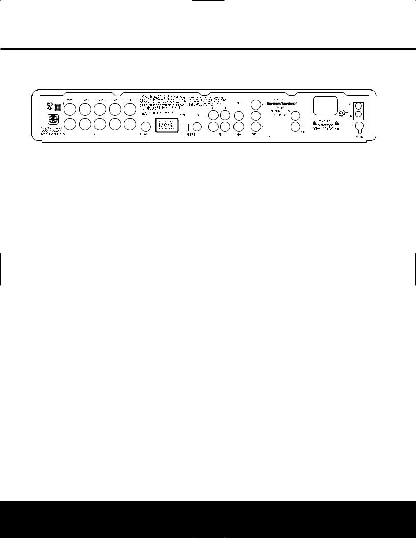
REAR-PANEL CONNECTIONS
|
|
|
|
|
|
|
|
|
|
|
|
|
|
|
|
|
|
|
|
|
|
|
|
|
|
|
|
|
|
|
|
|
|
|
|
|
|
|
|
|
|
|
|
|
|
|
|
|
|
|
|
|
|
|
|
|
|
|
|
|
|
|
|
|
|
|
|
|
|
|
|
|
|
|
|
|
|
|
|
|
|
|
|
|
|
|
|
|
|
|
|
|
|
|
|
|
|
|
|
|
|
|
|
|
|
|
|
|
|
|
|
|
|
|
|
|
|
|
|
|
|
|
|
|
|
|
|
|
|
|
|
|
|
|
|
|
|
|
|
|
|
|
|
|
|
|
|
|
|
|
|
|
|
|
|
|
|
|
|
|
|
|
|
|
|
|
|
|
|
|
|
|
|
|
|
|
|
|
|
|
|
|
|
|
|
|
|
|
|
|
|
|
|
|
|
|
|
|
|
|
|
|
|
|
|
|
|
|
|
|
|
|
|
|
|
|
|
|
|
|
|
|
|
|
|
|
|
|
|
|
|
|
|
|
|
|
|
|
|
|
|
|
|
|
|
|
|
|
|
|
|
|
|
|
|
|
|
|
|
|
|
|
|
|||||||||||||||||||
Center Speaker Outputs |
|
|
|
|
Coaxial Digital Input |
|
|
|
Component Video Outputs |
|
|
|||||||||||||||||||
Front Speaker Outputs |
|
|
|
|
Analog Audio Outputs |
|
|
|
TV Audio In |
|
|
|||||||||||||||||||
Surround Speaker Outputs |
|
|
|
|
Analog Audio In |
|
|
|
|
|
AC Power Cord Jack |
|
|
|||||||||||||||||
Subwoofer Output |
|
|
|
|
Composite Video Output |
|
|
|
FM Antenna |
|
|
|||||||||||||||||||
Optical Digital Input |
|
|
|
|
S-Video Output |
|
|
|
|
|
AM Antenna |
|
|
|||||||||||||||||
NOTE: To make it easier to follow the instructions that refer to this illustration, a larger copy may be downloaded from the Product Support section for this product at www.harmankardon.com.
Center Speaker Outputs: Connect these outputs to the matching + and – terminals on your center channel speaker. The Green terminal is the positive (+) terminal that should be connected to the Red (+) terminal on the speakers. Connect the Black (–) terminal on the HS 100 to the Black negative (–) terminal on your speaker. (See page 12 for more information on speaker polarity.)
Front Speaker Outputs: Connect these outputs to the matching + or – terminals on your left and right speakers. The White terminal is the positive (+) terminal that should be connected to the Red (+) terminal on Front Left speaker, while the Red terminal is the positive
(+) terminal that should be connected to the Red (+) terminal on Front Right speaker. Connect the Black (–) terminals on the HS 100 to the Black (–) terminals on the speakers. See page 11 for more information on speaker polarity.
Surround Speaker Outputs: Connect these outputs to the matching + and – terminals on your surround channel speakers. The Blue terminal is the positive (+) terminal that should be connected to the Red
(+) terminal on the Surround Left speaker, while the Gray terminal should be connected to the Red (+) terminal on the Surround Right speaker. Connect the Black (–) terminal on the HS 100 to the matching Black negative (–) terminals for each surround speaker. (See page 11 for more information on speaker polarity.)
NOTE: You’ll find more details about all Audio/Video connections under Setup and Connections on the following pages.
Subwoofer Output: Connect to the SUB/LFE input on the subwoofer.
Optical Digital Input: Connect the optical digital output from an HDTV receiver, LD player, MD player, satellite receiver or CD player to this jack. The signal may be a Dolby Digital signal, DTS signal or a standard PCM digital source.
Coaxial Digital Input: Connect the coax digital output from an HDTV receiver, LD player, MD player, satellite receiver or CD player to this jack. The signal may be a Dolby Digital signal, DTS signal or a standard PCM digital source. Do not connect the RF digital output of an LD player to these jacks.
Analog Audio Outputs: Connect these jacks to the Record/Input jacks of an audio recorder for recording.
Analog Audio In: Connect to the output of a
line-level analog audio source: TV, tape player, Minidisc, PC, etc.
Composite Video Output: Connect this jack to the video input on a television or video projector.
S-Video Output: Connect this jack to the S-video input on a television or video projector.
Component Video Outputs: These outputs carry the component video signals for connection to display monitors with component video inputs. For standard analog TVs or projectors with inputs marked Y/Pr/Pb or Y/Cr/Cb, connect these outputs to the corresponding
inputs. If you have a high-definition television or projector that is compatible with high-scan-rate progressive video, connect these jacks to the “HD Component” inputs. Note that if you are using a progressive scan display device, then “Progressive” must be selected in the Video Setup menu in order to take advantage of the progressive scan circuitry. See page 14 for more information on progressive scan video.
IMPORTANT: These jacks should NOT be connected to standard composite video inputs.
TV Audio In: Connect the analog left/right outputs of a cable TV set-top, satellite receiver, or the analog left/right stereo outputs from a video display with integrated digital tuner to these jacks.
AC Power Cord: Connect the AC power cord to this jack when the installation is complete. To ensure safe operation, use only the power cord supplied with the unit. If a replacement is required, it must be of the same type and capacity.
FM Antenna Jack: Connect to the supplied FM antenna.
AM Antenna: Connect the AM loop antenna supplied with the receiver to these terminals with the white wire connected to the “AM” terminal and the black wire connected to the “GND” terminal. If an external AM antenna is used, make connections to the AM and GND terminals in accordance with the instructions supplied with the antenna.
REAR-PANEL CONNECTIONS 7

REMOTE CONTROL
0 Power On
1 Transmit Indicator
2 Radio
3 Player
4 Repeat
5 Playlist
6 Display
7 Pic +/Pic –
8 Subtitle
9 Open/Close
A Navigation Buttons
B Status
C Numeric Keys
D Search/Slow Reverse
E Title
F Skip/Step (Previous)
G Skip/Step (Next)
H Pause
I STOP
J Search/Slow Forward
K Play
L Angle
M Zoom
N Clear
O OSD
P Enter
Q Disc Menu
Audio
Volume Control
A-B Repeat
Random
Digital In
AUX
TV
Mute Power Off
IR Transmitter Window
NOTE: To make it easier to follow the instructions that refer to this illustration, a larger copy may be downloaded from the Product Support section for this product at www.harmankardon.com.
0
1 2
3
4
5
6
7
8
9
A
B
C
D
E
F

Q
P
O
N
M
L
K
J
I
H
G
8 REMOTE CONTROL

REMOTE CONTROL
0 Power On: Press this button to turn the HS 100 on when it is in Standby mode.
1 Transmit Indicator: This LED will light red when any button is pressed to confirm that the remote code is being transmitted.
2 Radio: Press this button to select the internal tuner as the input source. When the tuner is in use, press this button to switch between the AM and FM frequency bands.
3 Player: Press this button to select the internal CD/DVD drive as the input source.
4 Repeat: Press this button to go to the Repeat menu. You can repeat a chapter, track or the
entire disc.
5 Playlist: Press this button to change the playback order of the disc.
6 Display: Press this button to change the brightness of the front-panel display or to turn the display off completely in the following order: FULL BRIGHTNESSHALF BRIGHTNESS OFF FULL BRIGHTNESS.
7 Pic +/Pic –: Press these buttons to move to the previous or next image when viewing JPEG images.
8 Subtitle: When a DVD is playing, press this button to select a subtitle language or to turn subtitles off.
9 Open/Close: Press this button to open or close the disc tray.
A Navigation Buttons (M / N /K/L): Press these buttons to move the cursor in the OSD.
B Status: Press this button while a disc is playing to view the banner display. Use the Navigation Buttons A to move through the different features in
the banner display. When a symbol is highlighted, press the Enter Button P on the remote to select it.
C Numeric Keys: Press this button to select numbers.
D Search/Slow (Rev.): Allows you to search in reverse through a disc while it is in Play mode. Each time you press this button, the search speed changes as indicated by a number of arrows on the right top of your screen. After pressing the Pause Button H and then pressing this button, each press will change the slow-play speed as indicated by the number of arrows on the right top of the screen.
E Title: When a disc is playing, press this button to go back to the first section of the disc.
F Skip/Step (Previous): Press this button to go to the beginning of the current track. Press it again quickly to go to the beginning of the previous track. After pressing the Pause Button H, each press of this button will move the image in reverse, frame by frame.
G Skip/Step (Next): Press this button to go to the beginning of the next track. After pressing the Pause Button H, each press of this button will move the image forward, frame by frame.
H Pause: Press this button to freeze a picture (with DVD/VCD) or pause playback (CD). Press it again for normal playback.
I Stop: Press this button to stop a disc. When a disc is playing, if you press STOP and the Play Button K, the disc will resume play; i.e., it will start from the same point on the disc where the unit was stopped.
If you press STOP twice and the Play Button K, the disc will start from the beginning.
J Search/Slow (Fwd.): Press this button to search forward through a disc while it is in Play mode. Each time you press this button, the search speed changes, as indicated by a number of arrows on the right top of your screen. After pressing the Pause Button H and then pressing this button, each press of this button will change the slow-play speed, as indicated by the number of arrows on the right top of the screen.
K Play: Press this button to begin playback of a disc. If the disc drawer is open, pressing this button will also close the drawer automatically.
L Angle: Press this button to access various camera angles on a DVD (if the DVD contains multiple camera angles) or to rotate JPEG images.
M Zoom: When a DVD or VCD is playing, press this button to zoom the picture. There are four steps to the zoom function, each progressively larger. Press through each of the zoom stages to return to a normal picture.
N Clear: Press this button to remove the Banner menu from the screen.
O OSD: Press this button to access the On-Screen Display menu.
P Enter: Press this button to activate a setting or option.
Q Disc Menu: Press this button to display the actual DVD Disc menu on the TV screen in Play mode. When playing discs with JPEG images, pressing this button will access the thumbnails.
Audio: Press this button to access various audio languages on a DVD (if the DVD contains multiple audio streams).
Volume (+ or –): Increase/decrease the master volume level.
A-B: Press this button to select section A-B and to play repeatedly.
Random: Press this button for Random playback in random order.
Digital In: Press this button to selects the audio device connected to either digital audio input as the input source.
AUX: Press this button to select the device connected to the Audio In Jacks 7 as the input source.
TV: Press this button to select the device connected to the TV In Audio Jacks B as the input source.
Mute: Press this button to mute the sound. Press the button again, or press either of the Volume Control Buttons , to return to normal audio output.
Power Off: Press this button to place the HS 100 in the Standby mode.
IR Transmitter Window: Point this window toward the HS 100 when pressing buttons on the remote to make certain that the infrared commands are properly received.
REMOTE CONTROL 9

INSTALLATION AND CONNECTIONS
Installation and Connections
After unpacking the HS 100 controller unit and the speakers, the first step is to place each speaker and the HS 100 controller unit in its location in your listening room. Consult the separate owner’s manual packed with the speaker system for detailed information on physical mounting of the speakers.
When making any connections between speakers and the HS 100, as well as between the HS 100 and other audio/video components, it is important that both the HS 100 and external components be turned off, preferably with the power removed from the AC outlet. This protects against accidental turn-on that might cause damage not covered by the products’ warranty.
When placing any speaker or the controller, make certain that it is on a solid surface capable of supporting its weight, and make certain that there is a means for connecting cables or speaker wires to reach through the back of any cabinets or shelves to the components they are connected to. As important, please note that due to the weight of the speaker cabinets, particularly the subwoofer, and the weight of and heat generated by the HS 100 controller, there is the remote possibility that the rubber padding on the bottom of the feet of the system components may leave marks on certain soft woods, wood veneers or carpets. Always use caution when placing any speaker or electronic component on a material that is soft or porous, or of a significantly different color than the feet or rubber padding on the component.
Speaker Placement
It is important that the speakers be placed in positions that enable them to do the best job of reproducing the sound as it was meant to be heard, regardless of the program content. Particularly in a multichannel 5.1 system, the placement of speakers can have a noticeable impact on the accuracy of the surround process.
When placing your speakers in a listening room, picture an imaginary circle starting at the center of your video screen that arcs around the room with the prime listening position, or “sweet spot” at the center of the circle. Depending on the number of speakers in your system, there is a recommended placement along the arc for each speaker, though the specific construction of your room (taking into account the available walls, bookcases, or floor space at which the speakers may be placed) will obviously have some impact on where the speakers are ultimately located. As a general rule, try to place all speakers so that they are positioned at the same height as your ears when you are seated at the prime listening position.
Use the following suggestions as a guide, and make the changes needed to fit the speakers to your room. Don’t be afraid to experiment a bit until you find the right combination of locations that works for you. There
is no real “right” or “wrong” place to put the speakers; work to optimize their locations so that audio moves across the front of the room smoothly, without seeming to jump from one speaker to another.
Video Screen
Center Speaker
Front Left |
Front Right |
Speaker |
Speaker |
30° |
30° |
110° |
110° |
Side Surround |
Side Surround |
Left Speaker |
Right Speaker |
Alternate position for surround positions
Center Channel Speaker
The ideal location for the center channel speaker is at “0 degrees” in our circle, directly in front of the prime listening position. Place the center channel speaker as close to the top (or bottom) of the video screen as possible so that when you position the front left/right speakers the tweeters of all three front channel speakers are within 24" of one another.
Front Left/Right Speakers
The recommended placement for front left/right speakers is to place them at the 30-degree position with reference to the center channel speaker. The distance between them should be about the same as the distance from the center channel speaker to the prime listening position.
Although the natural tendency is to place the speakers so they are parallel to the wall behind them, and thus in line with the video screen, the preferred placement is to angle the speakers slightly (“toe in”) so that they point to the prime listening position.
Surround Speakers
In a 5.1 surround system, an additional pair of left/right speakers is added to the front left, right and center speakers. Although many believe that these speakers should be placed at the rear of the room, the preferred position for them is at the sides of the room, with rear placement a second option when room conditions prevent the use of side-mounted surround speakers.
When side-wall mounting is possible, place the left/right surround speakers at a point that is 110 degrees along our circle from the center of the video screen. This translates to placing them to the side and slightly behind your preferred listening position. If possible, angle the speakers in slightly so that they are pointing toward the listener’s ears.
If it is not possible to place the surround speakers at the sides of the room, the alternate position is at the back of the room, about 150 degrees on our circle from the center of the video screen. Another way to spot the optimal, alternate rear-wall mounting position is to place the left surround speaker on the back wall so that it points directly at the front right speaker, and to have the right surround speaker point directly at the front left speaker. If possible aim the surround speakers so that they point “in” toward the listening area, rather than perpendicular to the walls.
NOTES ON SPEAKER PLACEMENT:
The limitations of your listening room, including the placement of walls and furniture, may make it difficult to follow the speaker placement suggestions shown above. Depending on the specific layout of the room, here are some ways to compensate for unusual conditions:
•Try to follow the suggested placement, but move the speakers within a few feet from the preferred locations.
•Regardless of where they are placed, always try to make certain that the main surround speakers are the same distance from the front speakers. (For example, try not to have the right surround speaker further back into the room than the left surround speaker.)
•If it is not possible to wall-mount or place speakers on a shelf, consider the use of optional floor stands.
Main Speaker Connections
Once you have placed your left, center, right and surround speakers in the listening room, use the speaker wire supplied with the HKTS 7 speaker system to connect the individual speakers to the rear panel of the HS 100. Follow the instructions in the HKTS 7 owner’s manual concerning connection of the speaker wire to the back of each of the main speakers.
To simplify installation, the speaker wire included with the HKTS 7 has a color marking tab at each end of the wire to indicate the channel the wire’s speaker is connected to. When connecting the wire to the speakers, we strongly recommend that you connect the wire in conformance with this color code, as it then makes it easier to match the color code for the speaker terminals on the HS 100.
The color coding is as shown below:
Speaker Position |
Cable Color Code |
Front Left |
White |
Center |
Green |
Front Right |
Red |
|
|
Surround Right |
Gray |
Surround Left |
Blue |
If you wish to shorten the length of the speaker wires, a set of colored stickers is included with the HKTS 7 owner’s manual. For consistency, apply the tab to the
10 INSTALLATION AND CONNECTIONS
INSTALLATION AND CONNECTIONS
side of the cable pair that has a white stripe. The speaker wires are not only color-coded for channel identification; they are also color-coded for polarity. Since proper polarity is important for system performance, note that the side of each cable pair with the white stripe and color tab is the positive side, and the pure black side of the cable pair is the negative. When connecting the cables to the speakers, the red speaker terminal is positive (+), and should be connected to the side of the wire with the white stripe and color tab. The pure black side of the cable, where there is no color tab, is negative and should be connected to the black speaker terminal.
Once the wires are connected at the speaker end, connect each speaker to the rear panel of the HS 100. The color-coding on the speaker wire connectors makes it easy to make the connections properly.
The positive (+) connection for the Front Speaker Connections are white for left and red for white, positive connection for the Center Speaker
Connection is green, and the positive connections for the Surround Speakers are blue for left and gray for left. In each case, the corresponding black side of each speaker cable is the negative (–) connection and goes to the matching black terminal for the speaker.
Subwoofer Placement and Connection
Since subwoofers produce nondirectional sound, they may be placed almost anywhere in a room. Actual placement should be based on room size and shape and the type of subwoofer used. One method of finding the optimal location for a subwoofer is to begin by placing it in the front of the room, about six inches from a wall, or near the front corner of the room. Another method is to temporarily place the subwoofer at your normal listening position, and then walk around the room until you find a spot where the subwoofer sounds best. Place the subwoofer in that spot, or you may wish to experiment with the best location for a subwoofer in your listening room.
Using the audio interconnect packaged with the HKTS 7 system, connect one end to the Subwoofer Output on the rear panel of the HS 100 and connect the other end to the “SUB” input on the subwoofer.
Audio Equipment Connections
Since the HS 100 is a complete integrated home theater system with an onboard DVD Audio/Video player and tuner, you may not need to make any additional audio equipment connections. However, if you have any external audio components, they should be connected as follows:
Products with digital audio outputs, such as an external CD changer, set-top cable box, satellite receiver, video game console, compatible computer sound card or HDTV receiver may be connected to either the Optical or Coaxial Digital inputs.
Connections to the analog audio output of a cable settop, satellite receiver, or the Left/Right analog output of a TV set with built-in digital television tuner should be connected to the TV Audio Inputs .
You may connect the outputs of any other analog audio device, such as a phono preamp, video game console, camcorder, audio recorder or similar to the Analog Audio Inputs . If you are connecting an audio recorder to the HS 100, the record/in jacks on the recording device should be connected to the Analog Audio Outputs on the HS 100.
Video Equipment Connections
Depending on the type of TV set or video display to be used, connect the HS 100 to the display using one of the following methods:
•If you have a high-definition, or “digital”, television, connect the Component Video Outputs to a matching set of component inputs on the display.
•If your TV set has only S-video and standard, composite video inputs, we recommend that the S-Video Output be used as the connection.
•When a standard, composite video input is all that is available on the TV set for video input, connect the
Composite Video Output to the TV.
System Connections
Connect the FM antenna supplied with the HS 100, or an optional, external FM antenna feed to the FM Antenna Jack . If the antenna uses 300-ohm twin-lead cable, you must use an optional 300-ohm to 75-ohm adaptor to make the connection. Assemble the supplied AM loop antenna so that the tabs at the bottom of the antenna loop snap into the holes in the base. Connect the white wire to the “AM” terminal and the black wire to the GND Terminals .
Connect the AC power cord to the AC Power Cord Jack , and then plug the cord into an unswitched AC outlet. Note that the ring surrounding the Power On/Off switch will turn amber to indicate that the
HS 100 is connected to an AC power source and in the Standby mode.
System Preparation
Remove the protective plastic film from the HS 100’s front-panel lens. If left in place, this film may affect the performance of the remote control.
Install the three supplied AAA batteries in the remote, as shown below.
To remove the battery cover, place your thumb on the round inset area on the door and gently press upward until the door slides out. When inserting the batteries be certain to follow the (+) and (–) polarity indications that appear at the bottom of the battery compartment. Replace the battery compartment cover by pressing it down toward the bottom of the remote until it snaps into place.
Connecting the AC Power
You are now ready to power up the HS 100 controller before beginning the final adjustments.
1.Plug the AC power cord into the AC Power Cord Jack C, and then into an unswitched AC outlet. Note that the Power Indicator 1 will turn orange, indicating that the unit is in the Standby mode.
2.Turn the HS 100 on either by pressing the Power On/Off 1 or the Input Source Selector 4 on the front panel, or via the remote by pressing the
Power On Button 0 on the remote. The Power Indicator 1 will turn blue to confirm that the unit is on, and the Main Information Display will also light up.
Congratulations! You have now completed the physical installation and connection of your HS 100 system and only a few configuration steps are needed to tailor the way the HS 100 operates to meet your needs and the requirements of your listening room. Please continue with the steps on the following pages to make certain that your new system delivers all the performance it was designed to provide.
INSTALLATION AND CONNECTIONS 11
 Loading...