


GEAR HEAD METAL LATHE
MODEL G4002 / G4003
INSTRUCTION MANUAL
COPYRIGHT © 2000 BY GRIZZLY INDUSTRIAL, INC.
WARNING: NO PORTION OF THIS MANUAL MAY BE REPRODUCED IN ANY SHAPE OR FORM WITHOUT THE WRITTEN APPROVAL OF GRIZZLY INDUSTRIAL, INC.
REVISED JANUARY, 2000 PRINTED IN CHINA

|
Table Of Contents |
|
|
|
PAGE |
1. |
SAFETY |
|
|
SAFETY RULES FOR POWER TOOLS .......................................................... |
2-3 |
|
ADDITIONAL SAFETY INSTRUCTIONS FOR METAL LATHES ........................ |
4 |
2. |
CIRCUIT REQUIREMENTS |
|
|
220V OPERATION .............................................................................................. |
5 |
|
EXTENSION CORDS .......................................................................................... |
5 |
|
GROUNDING ...................................................................................................... |
5 |
3. |
INTRODUCTION |
|
|
COMMENTARY.................................................................................................... |
6 |
|
UNPACKING ........................................................................................................ |
7 |
|
PIECE INVENTORY ............................................................................................ |
7 |
|
CLEAN UP............................................................................................................ |
8 |
|
SITE CONSIDERATIONS .................................................................................... |
8 |
4. |
ASSEMBLY & SETUP |
|
|
MOUNTING .......................................................................................................... |
9 |
|
LUBRICATION .................................................................................................... |
9 |
|
CHUCKS ........................................................................................................ |
9-10 |
|
LIVE CENTER .................................................................................................... |
10 |
|
STEADY REST .................................................................................................. |
11 |
|
FOLLOW REST.................................................................................................. |
11 |
|
4-JAW CHUCK ASSEMBLY .............................................................................. |
12 |
5. |
CONTROLS |
|
|
SPINDLE SPEEDS ............................................................................................ |
13 |
|
FEED DIRECTION ............................................................................................ |
14 |
|
SELECTING THE FEED ROD .......................................................................... |
14 |
|
QUICK CHANGE SELECTION .......................................................................... |
15 |
|
FEED RATE CHART.......................................................................................... |
15 |
|
THREAD SELECTION .................................................................................. |
16-19 |
|
CARRIAGE CONTROLS.................................................................................... |
20 |
|
TOOLPOST ........................................................................................................ |
21 |
|
TAILSTOCK CONTROLS .................................................................................. |
21 |
|
TEST RUN.......................................................................................................... |
22 |
6. |
ADJUSTMENTS |
|
|
GIBS.............................................................................................................. |
23-24 |
|
STEADY REST/FOLLOW REST........................................................................ |
24 |
|
TAILSTOCK .................................................................................................. |
25-26 |
7. |
MAINTENANCE |
|
|
LUBRICATION .............................................................................................. |
27-28 |
|
BEARING PRELOAD ........................................................................................ |
28 |
8. |
CLOSURE................................................................................................................ |
29 |
MACHINE DATA .......................................................................................................... |
30-31 |
|
PARTS BREAKDOWN AND PARTS LISTS ................................................................ |
32-49 |
|
WARRANTY AND RETURNS ............................................................................................ |
50 |
|

SECTION 1: SAFETY
For Your Own Safety Read Instruction Manual Before Operating This Equipment
The purpose of safety symbols is to attract your attention to possible hazardous conditions. This manual uses a series of symbols and signal words which are intended to convey the level of importance of the safety messages. The progression of symbols is described below. Remember that safety messages by themselves do not eliminate danger and are not a substitute for proper accident prevention measures.
|
|
|
|
|
Indicates an imminently hazardous situation which, if not |
|
|
|
|
|
|
avoided, WILL result in death or serious injury. |
|
|
|
|
|
|
|
Indicates a potentially hazardous situation which, if not |
|
|
|
|
|
|
|
|
|
|
|
|
|
|
|
|
|
|
|
|
avoided, COULD result in death or serious injury. |
|
|
|
|
|
|
|
|
|
|
|
|
Indicates a potentially hazardous situation which, if not |
|
|
|
|
|
|||
|
|
|
|
|
avoided, MAY result in minor or moderate injury. It may also |
|
|
|
|
|
|
be used to alert against unsafe practices. |
|
|
|
|
|
|||
|
|
|
|
|||
|
|
|
|
|
|
|
|
NOTICE |
|
|
This symbol is used to alert the user to useful information |
||
|
|
|
about proper operation of the equipment. |
|||
|
|
|
|
|
|
|
Safety Instructions For Power Tools
1.KEEP GUARDS IN PLACE and in working order.
2.REMOVE ADJUSTING KEYS AND WRENCHES. Develop a habit of checking to see that keys and adjusting wrenches are removed from tool before turning on.
3.KEEP WORK AREA CLEAN. Cluttered areas and benches invite accidents.
4.DON’T USE IN DANGEROUS ENVIRONMENT. Don’t use power tools in damp or wet locations, or where any flammable or noxious fumes may exist. Keep work area well lighted.
5.KEEP CHILDREN AND VISITORS AWAY. All children and visitors should be kept a safe distance from work area.
6.MAKE WORK SHOP CHILD PROOF with padlocks, master switches, or by removing starter keys.
7.DON’T FORCE TOOL. It will do the job better and safer at the rate for which it was designed.
8.USE RIGHT TOOL. Don’t force tool or attachment to do a job for which it was not designed.
-2- |
G4002/3 Gear Head' Lathes |

Safety Instructions For Power Tools
9.USE PROPER EXTENSION CORD. Make sure your extension cord is in good condition. Conductor size should be in accordance with the chart below. The amperage rating should be listed on the motor or tool nameplate. An undersized cord will cause a drop in line voltage resulting in loss of power and overheating. Your extension cord must also contain a ground wire and plug pin. Always repair or replace extension cords if they become damaged.
Minimum Gauge for Extension Cords
|
|
LENGTH |
|
||
AMP RATING |
25ft |
|
50ft |
|
100ft |
0-6 |
18 |
|
16 |
|
16 |
7-10 |
18 |
|
16 |
|
14 |
11-12 |
16 |
|
16 |
|
14 |
13-16 |
14 |
|
12 |
|
12 |
17-20 |
12 |
|
12 |
|
10 |
21-30 |
10 |
|
10 |
|
No |
|
|
|
|
|
|
10.WEAR PROPER APPAREL. Do not wear loose clothing, gloves, neckties, rings, bracelets, or other jewelry which may get caught in moving parts. Non-slip footwear is recommended. Wear protective hair covering to contain long hair.
11.ALWAYS USE SAFETY GLASSES. Also use face or dust mask if cutting operation is dusty. Everyday eyeglasses only have impact resistant lenses, they are NOT safety glasses.
12.SECURE WORK. Use clamps or a vise to hold work when practical. It’s safer than using your hand and frees both hands to operate tool.
13.DON’T OVERREACH. Keep proper footing and balance at all times.
14.MAINTAIN TOOLS WITH CARE. Keep tools sharp and clean for best and safest performance. Follow instructions for lubricating and changing accessories.
15.DISCONNECT TOOLS before servicing and changing accessories, such as blades, bits, cutters, and the like.
16.REDUCE THE RISK OF UNINTENTIONAL STARTING. Make sure switch is in off position before plugging in.
17.USE RECOMMENDED ACCESSORIES.
Consult the owner’s manual for recommended accessories. The use of improper accessories may cause risk of injury.
18.CHECK DAMAGED PARTS. Before further use of the tool, a guard or other part that is damaged should be carefully checked to determine that it will operate properly and perform its intended function. Check for alignment of moving parts, binding of moving parts, breakage of parts, mounting, and any other conditions that may affect its operation. A guard or other part that is damaged should be properly repaired or replaced.
19.NEVER LEAVE TOOL RUNNING UNATTENDED. TURN POWER OFF. Don’t leave tool until it comes to a complete stop.
G4002/3 Gear Head Lathes |
-3- |

Additional Safety Instructions For The Lathe
1.MAKE SURE ALL GUARDS are in place and that the lathe sits on a flat, stable surface.
2.BEFORE STARTING THE MACHINE be certain the workpiece has been properly engaged in the chuck and tailstock center (if in use) and that there is adequate clearance for full rotation.
3.ADJUST TOOL HOLDER to provide proper support for the turning tool you will be using. Test tool holder clearance by rotating workpiece by hand before turning lathe on.
4.SELECT THE TURNING SPEED which is appropriate for the type of work and the type of material. Allow the lathe to gain its full speed before beginning turning.
5.NEVER CHANGE FEED RATE or spindle speeds while the lathe is turning.
6.NEVER REVERSE MOTOR DIRECTION while the lathe is running.
7.DO NOT STOP LATHE USING YOUR HAND against the workpiece.
8.DO NOT LEAVE LATHE RUNNING UNATTENDED for any reason.
9.NEVER OPERATE THE LATHE WITH DAMAGED OR WORN PARTS. Maintain your lathe in proper working condition. Perform routine inspections and maintenance promptly when called for. Put away adjustment tools after use.
10.MAKE SURE YOUR METAL LATHE IS TURNED OFF, disconnected from its power source and all moving parts have come to a complete stop before starting any inspection, adjustment, or maintenance procedure.
11.KEEP LOOSE CLOTHING ARTICLES such as sleeves, belts or jewelry items away from the lathe spindle.
12.ALWAYS USE THE PROPER CUTTING TOOLS for the material you are turning, make certain they are sharp and that they are held firmly in the tool holder.
13.ALWAYS PLACE A BOARD OR PIECE OF PLYWOOD ACROSS THE BEDWAY when removing or installing chucks to avoid the possibility of a finger pinch point occurring between a loose chuck and the edges of the bedway.
No list of safety guidelines can be complete. Every shop environment is different. Always consider safety first, as it applies to your individual working conditions. Use this and other machinery with caution and respect. Failure to do so could result in serious personal injury, damage to equipment or poor work results.
Like all power tools, there is danger associated with the Model G4002/3 Metal Lathe. Accidents are frequently caused by lack of familiarity or failure to pay attention. Use this tool with respect and caution to lessen the possibility of operator injury. If normal safety precautions are overlooked or ignored, serious personal injury may occur.
-4- |
G4002/3 Gear Head Lathes |
SECTION 2: CIRCUIT REQUIREMENTS
220V Operation |
|
Grounding |
|
|
|
|
|
|
The Model G4002/3 is wired for 220 volt, single phase operation. The 2 HP motor will safely draw 9 amps at 220V. A 10-amp fuse or circuit breaker should be used when connecting this metal lathe. Circuits rated any higher are not adequate to protect the motor.
If you operate this lathe on any circuit that is already close to its capacity, it might blow a fuse or trip a circuit breaker. However, if an unusual load does not exist and a power failure still occurs, contact a qualified electrician or our service department.
Equipment returned to us for service that shows evidence of being over-fused will be repaired or replaced totally at the customer’s expense, regardless of the present warranty status.
Extension Cords
If you find it necessary to use an extension cord with the Model G4002/3, make sure the cord is rated Hard Service (grade S) or better. Refer to the chart in the standard safety instructions to determine the minimum gauge for the extension cord. The extension cord must also contain a ground wire and plug pin. Always repair or replace extension cords when they become worn or damaged.
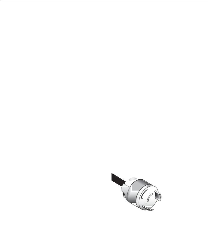
In the event of an electrical short, grounding reduces the risk of electric shock by providing a path of least resistance to disperse electric current. This tool is equipped with a power cord having an equipment-grounding conductor. See Figure 1. The outlet must be properly installed and grounded in accordance with all local codes and ordinances.
This equipment must be grounded. Verify that any existing electrical outlet and circuit you intend to plug into is actually grounded. If it is not, it will be necessary to run a separate 12 A.W.G. copper grounding wire from the outlet to a known ground. Under no circumstances should the grounding pin from any three-pronged plug be removed. Serious injury may occur.
Figure 1. Typical 220V plug and outlet.
|
|
|
|
|
|
|
|
|
|
|
|
G4002/3 Gear Head Lathes |
-5- |
||

SECTION 3: INTRODUCTION
Commentary
We are proud to offer the Grizzly Model G4002 / G4003 Gear Head Metal Lathe. The Model G4002 / G4003 is part of a growing Grizzly family of fine metalworking machinery. When used according to the guidelines set forth in this manual, you can expect years of trouble-free, enjoyable operation and proof of Grizzly’s commitment to customer satisfaction.
The Model G4002/3 is a precision metalworking lathe. It features cast iron construction, 24" or 36" V-bed, a speed range of 70-1,400 RPM, 9-speed gearbox and a complete electrical package. The electrical package consists of a 2 H.P., 110V / 220V motor, electro-magnetic motor control and overload protection. We also offer many accessories for this lathe. Please refer to the latest Grizzly catalog for prices and information.
We are also pleased to provide this instructional manual with the Model G4002 / G4003 Lathe. This manual was written to guide you through assembly, review safety considerations and cover basic operating procedures. It represents our latest effort to produce the best documentation possible. If you have any constructive criticisms or comments you feel we should include in our next printing, please write us at the address below.
Grizzly Industrial, Inc.
C/O Technical Documentation
P.O. Box 2069
Bellingham, WA 98227-2069
Most importantly, we stand behind our machines. If you have any service questions or parts requests, please call or write us at the location listed below.
Grizzly Industrial, Inc.
1203 Lycoming Mall Circle
Muncy, PA 17756
Phone: (570) 546-9663
Fax: (800) 438-5901 E-Mail: techsupport@grizzly.com Web Site: http://www.grizzly.com
The specifications, drawings, and photographs illustrated in this manual represent the Model G4002/3 as supplied when the manual was prepared. However, owing to Grizzly’s policy of continuous improvement, changes may be made at any time with no obligation on the part of Grizzly. Whenever possible, though, we send manual updates to all owners of a particular tool or machine. Should you receive one, we urge you to insert the new information with the old and keep it for reference.
To operate this, or any power tool, safely and efficiently, it is essential to become as familiar with its characteristics as possible. The time you invest before you begin to use your Model G4002/3 will be time well spent. DO NOT operate this machine until you are completely familiar with the contents of this manual. Make sure you read and understand all of the safety procedures. If you do not understand something, DO NOT operate the machine.
|
|
|
|
|
|
|
|
|
|
|
|
-6- |
G4002/3 Gear Head Lathes |
||

Unpacking
This Metal Lathe is shipped from the manufacturer in a carefully packed crate. If you discover the machine is damaged after you’ve signed for delivery, and the truck and driver are gone, you will need to file a freight claim with the carrier. Save the containers and all packing materials for possible inspection by the carrier or its agent. Without the packing materials, filing a freight claim can be difficult. If you need assistance determining whether you need to file a freight claim, or with the procedure to file one, please contact our Customer Service.
The G4002 and G4003 are heavy machines (1015 lbs. and 1040 lbs. shipping weight). DO NOT over-exert yourself while unpacking or moving your machine – get assistance. In the event that your Metal Lathe must be moved up or down a flight of stairs, be sure that the stairs are capable of supporting the combined weight of people and the machine. Serious personal injury may occur.
When you are completely satisfied with the condition of your shipment, you should inventory its parts.
Piece Inventory
The Model G4002/3 is, for the most part, preassembled at the factory. Inside the crate you’ll find:
•The Model G4002/3 Metal Lathe
•6" 3-jaw Chuck
•8" 4-jaw Chuck
•Face Plate
•Steady Rest
•Follow Rest
•Quick Change Tool Post
•Tool Holder
•Toolbox
•Metric Allen® Wrenches
•Straight Blade Screwdriver
•Phillips® Screwdriver
•Oil can
•26T Gear
•27T Gear
•35T Gear
•2- 40T Gear
•45T Gear
•50T Gear
•Chuck wrenches (2)
•Reverse Jaws for the 3-Jaw Chuck
•Dead Center - MT #3
•Live Center - MT #3
In the event that any non-proprietary parts are missing (e.g. a nut or a washer), we would be glad to replace them, or, for the sake of expediency, replacements can be obtained at your local hardware store.
|
|
|
|
|
|
|
|
|
|
|
|
G4002/3 Gear Head Lathes |
-7- |
||
Clean Up |
Site Considerations |
|
|
|
|
|
|
|
The unpainted surfaces are coated with a waxy oil to protect them from corrosion during shipment. Remove this protective coating with a solvent cleaner or citrus-based degreaser, like Grizzly’s G7895 Citrus Engine Degreaser. Avoid chlorine-based solvents as they may damage painted surfaces should they come in contact. Always follow the usage instructions on the product you choose for clean up.
Many of the solvents commonly used to clean machinery can be highly flammable, and toxic when inhaled or ingested. Always work in well-ventilated areas far from potential ignition sources when dealing with solvents. Use care when disposing of waste rags and towels to be sure they do not create fire or environmental hazards. Keep children and animals safely away when cleaning and assembling this machine.
Do not use gasoline or other petroleumbased solvents to remove this protective coating. These products generally have low flash points which makes them extremely flammable. A risk of explosion and burning exists if these products are used. Serious personal injury may occur.
All die-cut metal parts have a sharp edge (called “flashing”) on them after they are formed. This is generally removed at the factory. Sometimes a bit of flashing might escape inspection, and the sharp edge may cause cuts or lacerations when handled. Please examine the edges of all die-cut metal parts and file or sand the edge to remove the flashing before handling.
1.Floor Load: The Model G4002/3 can be mounted on your existing workbench or on an optional cabinet stand which is listed in our current Grizzly catalog. If you choose to use the stand, you will find the holes for bolting the G4002/3 to the stand are already in place. If you are using your own bench, ensure that it is strong enough to handle the weight of the G4002/3 lathe. Keep in mind, whichever way you choose to mount the lathe, it’s essential that the mounting surface be perfectly flat. Use an accurate carpenter’s level to ensure that your bench is properly leveled.
2.Working Clearances: Consider existing and anticipated needs, size of material to be processed through each machine, and space for auxiliary stands, work tables or other machinery when establishing a location for your lathe.
3.Lighting and Outlets: Lighting should be bright enough to eliminate shadow and prevent eye strain. Electrical circuits should be dedicated or large enough to handle amperage requirements. Outlets should be located near each machine so power or extension cords are clear of high-traffic areas. Observe local electrical codes for proper installation of new lighting, outlets, or circuits.
Make your shop “child safe”. Ensure that your workplace is inaccessible to youngsters by closing and locking all entrances when you are away. Never allow visitors in your shop when assembling, adjusting or operating equipment.
-8- |
G4002/3 Gear Head Lathes |
SECTION 4: ASSEMBLY & SETUP
Mounting |
Chucks |
|
|
|
|
|
|
|
This lathe should be securely mounted to a stand or bench top. An accessory stand is available from Grizzly, please see our current catalog for pricing. There are 2 holes in the base at the tailstock end of the lathe and four holes on the gearhead end which can be used to secure the machine to a stand.
The lathe does not require a great deal of assembly. This section details the installation of the various accessory holding devices. The following section will familiarize you with the controls for your new lathe. After you have completed both of these sections we will do a test run of the machine. Do not attempt a test run until you have become familiar with both of these sections.
DO NOT attempt to start this machine until you have completed all of the assembly and control familiarization steps. When performing the assembly steps, ensure that the switch is off and the power is disconnected. Failure to comply with this could cause inadvertent starting of the machine which can result in serious operator injury.
Lubrication
The G4002/3 is shipped from the factory prelubricated. However, it is recommended that you go through the entire lubrication sequence before operating the machine. Review Section 7: Maintenance for lubrication instructions.
Lubrication must be completed before you start your new lathe.
The Model G4002/3 Metal Lathe comes equipped with a 6'' 3-jaw chuck (already installed), a 8'' 4- jaw chuck and a face plate.
The 3-jaw chuck is a scroll-type chuck, meaning that all three jaws move in unison when adjustments are made. The 4-jaw chuck, on the other hand, features independent jaws. The 4-jaw chuck is used for square or unevenly-shaped stock.
The 3 and 4-jaw chucks have a D-1 Camlock mount. Please note that there are lines stamped into the cam and on the chuck body. A chuck key is used to turn the locking cams as in Figure 2.
Figure 2. Key positioned to remove chuck.
ALWAYS place a piece of plywood over the ways of the lathe before removing or installing a chuck. This helps by covering the sharp corners of the bed, protecting your hands and fingers. Use extreme care when removing or installing a chuck so that your hands do not become trapped between the chuck and the plywood.
G4002/3 Gear Head Lathes |
-9- |

To remove a chuck:
1.Place a piece of plywood across the lathe bed and position it just under the chuck. The board should be at least 8" wide and 10" long.
Never leave a chuck key in the chuck when it is not in use. If the machine is accidentally started with this in place, it can become a projectile and cause serious injury.
Figure 3. Cam lines aligned to spindle line.
2.Turn a cam, with the chuck key, in the lathe spindle in a counter-clockwise rotation until the line on the cam is aligned with the line going across the spindle housing as in
Figure 3.
The chuck is heavy and can be awkward to handle. Be aware that when removing or installing a chuck a finger pinch situation exists.
3.Turn the other cams in the same way. Make sure to support the chuck with one hand as you align the last cam. The chuck may come off at this point so it is important you are ready to support its weight.
4.Remove the chuck key.
If the chuck is still tight on the spindle:
Tap the back of the chuck with a rubber or wooden mallet while supporting the bottom of the chuck with your free hand. If the chuck does not immediately come off, rotate the spindle approximately 60˚ and tap again. Make sure all the marks on the cams and spindle are in proper alignment.
To install a chuck:
1.Place a piece of plywood across the lathe bed and position it just under the spindle.
2.Lift the chuck up to the spindle and align the pins in the back with the holes on the spindle’s face and insert the pins.
3.While supporting the weight of the chuck, turn one cam with the chuck key until the cam line is between the two vees on the spindle. Do not tighten at this time.
4.Rotate the spindle and repeat step 3 on the last two cams.
5.Return to the first cam and snug it up. Repeat with the rest of the cams.
6.Finally, tighten all three cams.
-10- |
G4002/3 Gear Head Lathes |
Live Center |
|
Steady Rest |
|
|
|
|
|
|
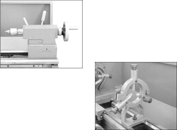
The live center is used to support stock which is too long to be supported by the chuck alone. Stock protruding more than three times its diameter should be supported by the live center.
Figure 4. Live center installed in tailstock.
The tailstock barrel and live center have a Morse taper #3. Before assembling these, insure that the mating surfaces are “white glove” clean. These parts will last longer and remain accurate when properly maintained. Morse tapers will not interlock when oil is present on the mounting surfaces. Insert the end of the live center into the tailstock bore until it seats. The force of a mounted workpiece will fully seat the taper.
When using a live center, the tailstock barrel should protrude about 1⁄2'' and not more than 3''.
See Figure 4.
To remove the live center, back the tailstock barrel all the way into the tailstock casting. The live center will pop out. Be sure to catch it when it comes out to avoid damaging the tip.
The steady rest supports long, small diameter stock that otherwise could not be turned. The steady rest can also replace the tailstock to allow for cutting tool access at the outboard end of your workpiece.
To mount the steady rest:
1.Secure to bedway from below with the locking plate.
2.A single hex bolt, along with a nut and washer, is used to hold the steady rest in place. See Figure 5.
3.The bearing surfaces on the steady rest should receive periodic lubrication while in use to prevent premature wear.
Figure 5. Steady rest in place.
G4002/3 Gear Head Lathes |
-11- |
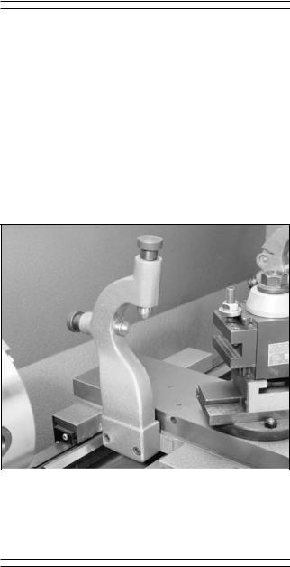
Follow Rest
The follow rest is normally used with small diameter stock to prevent the workpiece from “springing” under pressure from the turning tool. To install the follow rest:
1.The follow rest is secured to the saddle with two cap screws. See Figure 6.
2.The bearing surfaces on the follow rest are similar to those on the steady rest, and should be lubricated to prevent premature wear.
Figure 6. Follow rest secured to saddle.
4-Jaw Chuck
The 4-jaw chuck supplied with the G4002/3 is not mounted to the back plate. Assembly of the back plate components is also required.
1.Make note of the reference lines on each of the 3-jaw chuck studs. Thread each of the 4-jaw chuck cam lock studs into the 4- jaw chuck back plate to the exact same depth as the 3-jaw studs. Screw in the locking cap screws.
2.Mount the back plate on the spindle.
3.Accurately measure the inside of the back relief bore on the 4-jaw chuck. This dimension is critical, ± .001''.
4.Face the back plate to true it. Make passes across the face until its entire surface has been cut.
5.Turn a shoulder into the face 1⁄8'' deep and
.001" to .002'' larger than the back relief bore diameter. Chamfer the corner a small amount.
6.Set the chuck on the back plate aligning the shoulder with the relief bore. Use a transfer punch to mark the back plate. If a transfer punch is not available, a drill bit of the same size as the mounting holes in the chuck can be used. Lightly tap on the bit, rotate it 90° and tap it again.
7.Remove the chuck from the back plate and center punch the marks. Drill and tap the holes for 3⁄8''-16.
8.Set the chuck on the back plate. Line up the mounting holes and thread in the cap screws supplied. Remember that this is a
.001" to .002" press fit. Snug up the first cap screw then alternate to the cap screw across the chuck. Alternating the tightening process insures the chuck will go on straight. This step should be repeated until the back plate fits snugly against the chuck. If the chuck fits loosely on the back plate, or is crooked on the shoulder, it will be necessary to face and shoulder the back plate again.
-12- |
G4002/3 Gear Head Lathes |
SECTION 5: CONTROLS
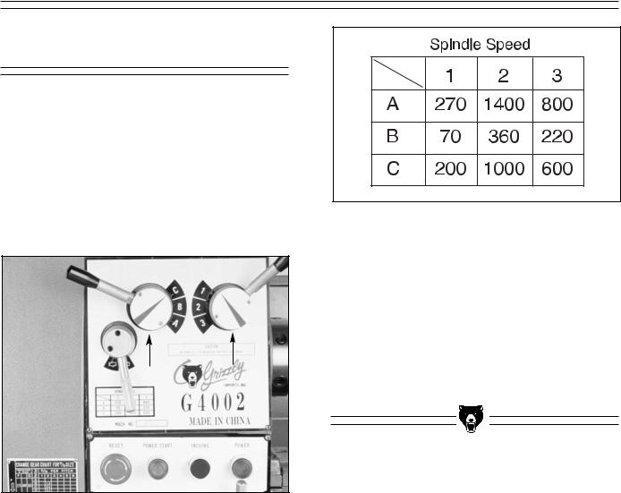
Spindle Speeds
Never change speeds while spindle or motor is in motion.
The speed of the spindle is controlled by the positions of the speed control knobs. See Figure 7. By positioning the knobs using the chart in Figure 8, you can achieve all of these speed ranges: 70, 200, 220, 270, 360, 600, 800, 1000 and 1400 RPM.
Figure 7. Speed shifting levers.
Figure 8. Speed chart.
The chart above shows the various combinations of knob positions for achieving a desired speed.
Example:
To select a spindle speed of 600 RPM, move the left-hand selector knob until the indicator arrow on its hub is pointing to the “C”. Move the righthand selector knob until its indicator arrow is pointed at the “3”.
G4002/3 Gear Head Lathes |
-13- |
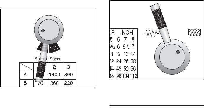
Feed Direction |
|
Selecting the Feed Rod |
|
|
|
|
|
|
Never move selection levers while machine is running.
The G4002/3 Metal Lathe can cut left or right while feeding or threading and across both ways for facing operations. This feed direction is controlled by the selection knob as shown in Figure 9.
Figure 9. Directional control lever.
When the selection knob is positioned as depicted in Figure 9, the apron will move to the right along the bed or the cross feed will travel away from the operator. The cross feed and longitudinal feed selection is controlled on the apron and will be discussed later.
To reverse the direction of the feeding or threading operation, rotate the selection knob to the right. It should be noted that when the lever is positioned in the middle, no direction is selected and all of the drive mechanisms after this point are in neutral.
Important:
Do not force any selection lever on the machine. If the lever will not engage, rotate the chuck by hand while keeping light pressure on the selector. As the chuck rotates it aligns the gears and the selector will engage.
The feed rod can be selected by rotating the handle to the left as in Figure 10. Use this position for all feeding operations. When the lever is positioned straight up, no drive device is selected and the gear train is in neutral after this point.
Figure 10. Feed rod selected.
Quick Change Selection
The two levers at the bottom of the headstock change the feed rate, or the number of threads- per-inch. This section of the machine is commonly known as the Quick Change Gear Box. See Figure 11. The left-hand lever can be engaged in any of five different positions and are listed on the charts as A, B, C, D, and E. The right-hand lever has 8 positions and are listed on the charts as 1 through 8.
The machine label describes some of the more typical settings which might be used. Figure 12 shows the feed rate chart located on the gear cover of the lathe. The chart is divided into metric feed rates and inch feed rates.
-14- |
G4002/3 Gear Head Lathes |
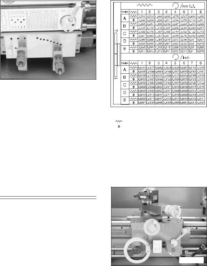
Figure 11. Feed rate selector levers.
Important:
Do not force any selection lever on the machine. If the lever will not engage, rotate the chuck by hand while keeping light pressure on the selector. As the chuck rotates, it aligns the gears and the selector will engage.
To change the position of the feed selector, pull the knurled handle. This disengages a pin which is inserted into a selection hole. Position the lever in the down position and slide to the right or left until it is positioned below the desired selection hole. Raise the lever with one hand while pulling the handle with the other. The pin at the end of the lever should align with the selection hole. If it does not, rotate the feed rod or chuck by hand while maintaining gentle pressure on the lever.
Feed Rate Chart
To perform a longitudinal cut in inches, use the bottom portion of the chart. If the desired feed rate is 0.0062"/revolution, look at the longitudinal ranges. According to the chart we would put the left-hand lever in the “C” position and the righthand lever in the “4” position. Metric calculations would be done the same way. To perform a cross feed cut with a feed rate of 0.0013" move the lefthand lever to the “D” position and the right-hand lever to the “1” position.
Please note that when either of the two selector levers are left in the down position, the drive train after this point is in neutral.
G4002/3 Gear Head Lathes
Figure 12. Feed rate selection.
This symbol indicates longitudinal feed. This symbol indicates cross feed rates.
Feed Lever - Longitudinal and cross slide powered motions are controlled by the feed lever. The lever pivots through two stops which require moving the lever left and right as well as up and down. Moving this lever upward activates the automatic longitudinal feed. Moving the lever down activates the cross slide. See Figure 13.
Feed lever
Figure 13. Feed lever in neutral postition.
-15-
 Loading...