


HEAVY-DUTY MILL/DRILL
MODEL G1006/G1007
INSTRUCTION MANUAL
COPYRIGHT © 1999 BY GRIZZLY INDUSTRIAL, INC.
WARNING: NO PORTION OF THIS MANUAL MAY BE REPRODUCED IN ANY SHAPE OR FORM WITHOUT THE WRITTEN APPROVAL OF GRIZZLY INDUSTRIAL, INC.
OCTOBER, 1999 PRINTED IN U.S.A.
|
Table Of Contents |
|
|
|
PAGE |
1. |
SAFETY |
|
|
SAFETY INSTRUCTIONS FOR POWER TOOLS ............................................................ |
3-4 |
|
ADDITIONAL SAFETY INSTRUCTIONS FOR MILL/DRILLS .............................................. |
5 |
2. |
CIRCUIT REQUIREMENTS |
|
|
110V OPERATION ................................................................................................................ |
6 |
|
CIRCUIT LOAD/RESET ........................................................................................................ |
6 |
|
EXTENSION CORDS ............................................................................................................ |
6 |
|
GROUNDING ........................................................................................................................ |
6 |
|
220V OPERATION ................................................................................................................ |
7 |
|
CIRCUIT LOAD/RESET ........................................................................................................ |
7 |
|
GROUNDING ........................................................................................................................ |
7 |
|
EXTENSION CORDS ............................................................................................................ |
7 |
3. |
INTRODUCTION |
|
|
COMMENTARY .................................................................................................................... |
8 |
|
UNPACKING.......................................................................................................................... |
9 |
|
PIECE INVENTORY .............................................................................................................. |
9 |
|
CLEAN UP .......................................................................................................................... |
10 |
|
SITE CONSIDERATIONS.................................................................................................... |
10 |
4. |
ASSEMBLY |
|
|
BEGINNING ASSEMBLY .................................................................................................... |
11 |
|
MOUNTING.......................................................................................................................... |
11 |
|
DRILLING VISE .................................................................................................................. |
11 |
|
POWER FEED .................................................................................................................... |
12 |
|
HANDWHEELS.................................................................................................................... |
13 |
|
COLLET/ARBOR ................................................................................................................ |
13 |
|
DRILL CHUCK/ARBOR ...................................................................................................... |
14 |
|
FLY CUTTER/ARBOR ........................................................................................................ |
14 |
5. |
ADJUSTMENTS |
|
|
GRADUATED DIALS .......................................................................................................... |
15 |
|
SPINDLE HEIGHT .............................................................................................................. |
15 |
|
DEPTH STOP ...................................................................................................................... |
15 |
|
SPEED CHANGES .............................................................................................................. |
16 |
|
HEAD HEIGHT .................................................................................................................... |
16 |
6. |
OPERATIONS |
|
|
POWER FEED.................................................................................................................... |
17 |
|
TABLE MOVEMENT............................................................................................................ |
17 |
|
TEST RUN .......................................................................................................................... |
18 |
7.MAINTENANCE
|
GENERAL............................................................................................................................ |
19 |
|
GIBS .................................................................................................................................... |
19 |
|
LUBRICATION .................................................................................................................... |
20 |
|
QUILL .................................................................................................................................. |
20 |
|
V-BELTS .............................................................................................................................. |
20 |
|
RETURN SPRING TENSION .............................................................................................. |
21 |
|
TABLE LEADSCREWS ...................................................................................................... |
21 |
8. |
CLOSURE .................................................................................................................................. |
22 |
WARRANTY AND RETURNS .............................................................................................................. |
23 |
|
G1006/G1007 Mill/Drill |
-2- |

SECTION 1: SAFETY
For Your Own Safety Read Instruction Manual Before Operating This Equipment
The purpose of safety symbols is to attract your attention to possible hazardous conditions. This manual uses a series of symbols and signal words which are intended to convey the level of importance of the safety messages. The progression of symbols is described below. Remember that safety messages by themselves do not eliminate danger and are not a substitute for proper accident prevention measures.
|
|
|
|
|
|
|
|
|
Indicates an imminently hazardous situation which, if not |
|
|
|
|
|
|
|
|
|
avoided, WILL result in death or serious injury. |
|
|
|
|
|
|
|
|
|
|
|
|
|
|
|
|
|
|
|
Indicates a potentially hazardous situation which, if not |
|
|
|
|
|
|
|
|
|
|
|
|
|
|
|
|
|
|
|
|
|
|
|
|
|
|
|
|
|
avoided, COULD result in death or serious injury. |
|
|
|
|
|
|
|
|
|
|
|
|
|
|
|
|
|
|
|
Indicates a potentially hazardous situation which, if not |
|
|
|
|
|
|
|
|
||
|
|
|
|
|
|
|
|
|
avoided, MAY result in minor or moderate injury. It may also |
|
|
|
|
|
|
|
|
|
be used to alert against unsafe practices. |
|
|
|
|
|
|
|
|
||
|
|
|
|
|
|
|
|
|
|
|
|
NOTICE |
|
This symbol is used to alert the user to useful information |
|||||
|
|
|
about proper operation of the equipment. |
||||||
|
|
|
|
|
|
|
|
|
|
Safety Instructions For Power Tools
1.KEEP GUARDS IN PLACE and in working order.
2.REMOVE ADJUSTING KEYS AND WRENCHES. Form habit of checking to see that keys and adjusting wrenches are removed from tool before turning on.
3.KEEP WORK AREA CLEAN. Cluttered areas and benches invite accidents.
4.DON’T USE IN DANGEROUS ENVIRONMENT. Don’t use power tools in damp or wet locations, or where any flammable or noxious fumes may exist. Keep work area well lighted.
5.KEEP CHILDREN AND VISITORS AWAY. All children and visitors should be kept a safe distance from work area.
6.MAKE WORK SHOP CHILD PROOF with padlocks, master switches, or by removing starter keys.
7.DON’T FORCE TOOL. It will do the job better and safer at the rate for which it was designed.
8.USE RIGHT TOOL. Don’t force tool or attachment to do a job for which it was not designed.
-3- |
G1006/G1007 Mill/Drill |

Safety Instructions For Power Tools
9.USE PROPER EXTENSION CORD. Make sure your extension cord is in good condition. Conductor size should be in accordance with the chart below. The amperage rating should be listed on the motor or tool nameplate. An undersized cord will cause a drop in line voltage resulting in loss of power and overheating. Your extension cord must also contain a ground wire and plug pin. Always repair or replace extension cords if they become damaged.
Minimum Gauge for Extension Cords
|
|
LENGTH |
|
||
AMP RATING |
25ft |
|
50ft |
|
100ft |
0-6 |
18 |
|
16 |
|
16 |
7-10 |
18 |
|
16 |
|
14 |
11-12 |
16 |
|
16 |
|
14 |
13-16 |
14 |
|
12 |
|
12 |
17-20 |
12 |
|
12 |
|
10 |
21-30 |
10 |
|
10 |
|
No |
|
|
|
|
|
|
10.WEAR PROPER APPAREL. Do not wear loose clothing, gloves, neckties, rings, bracelets, or other jewelry which may get caught in moving parts. Non-slip footwear is recommended. Wear protective hair covering to contain long hair.
11.ALWAYS USE SAFETY GLASSES. Also use face or dust mask if cutting operation is dusty. Everyday eyeglasses only have impact resistant lenses, they are NOT safety glasses.
12.SECURE WORK. Use clamps, fixtures or vise to hold work. Never use hands to hold workpiece for any operation.
13.DON’T OVERREACH. Keep proper footing and balance at all times.
14.MAINTAIN TOOLS WITH CARE. Keep tools sharp and clean for best and safest performance. Follow instructions for lubricating and changing accessories.
15.DISCONNECT TOOLS before servicing and changing accessories, such as arbors, bits, cutters, and the like.
16.REDUCE THE RISK OF UNINTENTIONAL STARTING. Make sure switch is in off position before plugging in.
17.USE RECOMMENDED ACCESSORIES.
Consult the owner’s manual for recommended accessories. The use of improper accessories may cause risk of injury.
18.CHECK DAMAGED PARTS. Before further use of the tool, a guard or other part that is damaged should be carefully checked to determine that it will operate properly and perform its intended function. Check for alignment of moving parts, binding of moving parts, breakage of parts, mounting, and any other conditions that may affect its operation. A guard or other part that is damaged should be properly repaired or replaced.
19.NEVER LEAVE TOOL RUNNING UNATTENDED. TURN POWER OFF. Don’t leave tool until it comes to a complete stop.
G1006/G1007 Mill/Drill |
-4- |
Additional Safety Instructions Mill / Drills
1.DO NOT use until unit is completely assembled and installed according to instructions.
2.DO NOT use the Mill/Drill until all controls and adjustments are understood.
3.BE SURE drill bit or cutter is securely locked in the chuck or holder.
4.USE recommended speeds and feed rate for cutter or drill accessory and workpiece material.
5.ADJUST table or depth stop to prevent drilling into table work surface.
6.KEEP FLOOR AREA around the Mill/Drill free from oil, tools, and chips.
7.NEVER use your hands to hold workpiece during milling or drilling. Clamp it to work surface or use a vise to secure workpiece and prevent rotation.
8.DO NOT WEAR GLOVES, neckties, or loose fitting clothing. Roll up long sleeves. Tie back long hair. Do not use a rag around a rotating cutter. These could get pulled into the cutter and cause severe injury
9.ALWAYS use a brush to remove chips after the cutter has stopped. Never use a rag to remove chips.
10.NEVER operate Mill/Drill if any part is damaged or broken until it is properly repaired or replaced.
11.NEVER place your fingers in a position where drill or cutter could contact them if a part shifts unexpectedly. Serious personal injury could result.
12.NEVER perform layout, assembly, or setup work on the mill while a bit or cutter is rotating.
13.SHUT OFF POWER, remove drill or cutting tool, and clean tool before leaving machine.
Like all power tools, there is danger associated with the Model G1006 and G1007 Milling/Drilling Machines. Accidents are frequently caused by lack of familiarity or failure to pay attention. Use this tool with respect and caution to lessen the possibility of operator injury. If normal safety precautions are overlooked or ignored serious personal injury may occur.
No list of safety guidelines can be complete. Every shop environment is different. Always consider safety first, as it applies to your individual working conditions. Use this and other machinery with caution and respect. Failure to do so could result in serious person injury, damage to equipment or poor work results.
-5- |
G1006/G1007 Mill/Drill |

SECTION 2: CIRCUIT REQUIREMENTS
110V Operation |
|
Grounding |
|
|
|
|
|
|
The Model G1006/G1007 is wired for 110V, single phase operation. The 2 HP motor will draw 22 amps at 110V at maximum load. If you operate this Mill/Drill on any circuit that is already close to its capacity, it may blow a fuse or trip a circuit breaker. However, if an unusual load does not exist and a power failure still occurs, contact a qualified electrician or our service department.
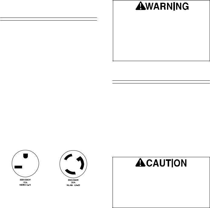
In the event of an electrical short, grounding reduces the risk of electric shock by providing a path of least resistance to disperse electric current. This tool is equipped with a power cord having an equipment-grounding conductor. See Figure 1. The outlet must be properly installed and grounded in accordance with all local codes and ordinances.
Circuit Load/Reset
The Model G1006/G1007 can be fused at 20 amps. If the circuit breakers trip frequently, and you have determined you are on a dedicated circuit with no other loads, it may be necessary to upgrade to a 25 amp circuit. Contact a qualified electrician to specifically determine the needs for your shop.
You will find that the motor supplied with the Mill/Drill is equipped with a reset button. If during operation the reset button disengages power from the motor, allow it to cool for five minutes. Depress the button. It should stay down and the motor should start by pressing the start switch. If the reset button continues to deactivate the motor or if it will not reset, call the Service Department.
Extension Cords
If you find it necessary to use an extension cord with the Model G1006/G1007, make sure the cord is rated Hard Service (grade S) or better. Refer to the chart in Section 1: Safety Instructions to determine the minimum gauge for the extension cord. The extension cord must also contain a ground wire and plug pin. Always repair or replace extension cords when they become worn or damaged.
G1006/G1007 Mill/Drill
This equipment must be grounded. Verify that any existing electrical outlet and circuit you intend to plug into is actually grounded. If it is not, it will be necessary to run a separate 12 A.W.G. copper grounding wire from the outlet to a known ground. Under no circumstances should the grounding pin from any three-pronged plug be removed. Serious injury may occur.
Figure 1. Grounded plug configuration.
-6-
220V Operation |
|
Grounding |
|
|
|
|
|
|
The Model G1006/G1007 can be wired for 220V single phase operation (see Wiring Diagram, page 23). The motor will safely draw about 11 amps at 220V under load. If you operate the Mill/Drill on any circuit that is already close to its capacity, it might blow a fuse or trip a circuit breaker. However, if an unusual load does not exist, and power failure still occurs, have the circuit inspected by a qualified electrician.
Circuit Load/Reset
The Model G1006/G1007 should be fused at 15 amps. Fusing at amperage ratings higher than 15 amps will not adequately protect the circuit. You will find that the motor supplied with the Mill/Drill is equipped with a reset button. If during operation the reset button disengages power from the motor allow it to cool for five minutes. Depress the button. It should stay down and the motor should start by pressing the start switch. If the reset button continues to deactivate the motor or if it will not reset call the Service Department.
In preparing to connect the Model G1006/G1007 to your existing or new circuit, it will be necessary to connect a plug that matches your 220V receptacle. If you will be installing a new receptacle and plug, we recommend either of the styles shown in Figure 2. Note that you have the choice between simple plug-in and twist-lock plug styles. Whichever style you choose, be sure that both the plug and outlet are rated at 15 amps or better.
Standard |
Locking |
|
|
|
|
|
|
|
|
|
|
Figure 2. Two typical outlet/plug configurations.
-7-
In the event of a malfunction or breakdown, grounding provides a path of least resistance for electric current to reduce the risk of electric shock. This tool is equipped with an electric cord having an equipment-grounding conductor which must be properly connected to a grounding plug. The plug must be plugged into a matching outlet that is properly installed and grounded in accordance with all local codes and ordinances.
This equipment must be grounded. Verify that any existing electrical outlet and circuit you intend to plug into is actually grounded. If it is not, it will be necessary to run a separate 12 A.W.G. copper grounding wire from the outlet to a known ground. Under no circumstances should the grounding wire be left unconnected when installing the 220V plug. Serious injury may occur.
Extension Cords
We do not recommend the use of extension cords on 220V equipment. It is much better to arrange the placement of your equipment and the installed wiring to eliminate the need for extension cords. Should it be necessary to use an extension make sure the cord is rated Hard Service (grade S) or better. Refer to the chart in
Section 1: Safety Instructions to determine the minimum gauge for the extension cord. The extension cord must also contain a ground wire and plug pin. Always repair or replace extension cords when they become worn or damaged.
The electrical requirements presented here are are not necessarily comprehensive. You must be sure that your particular electrical configuration complies with local and state codes. Ensure compliance by checking with your local municipality or a licensed electrician.
G1006/G1007 Mill/Drill
 Loading...