


MODEL G0555LX
14" DELUXE BandsaW
OWNEr'S Manual
(For models manufactured since 3/13)
177335
Copyright © February, 2012 By Grizzly Industrial, Inc., Revised april, 2013 (ts)
Warning: No portion of this manual may be reproduced in any shape Or form without the written approval of Grizzly Industrial, inc.
#KN14662 printed in TAIWAN

This manual provides critical safety instructions on the proper setup, operation, maintenance, and service of this machine/tool. Save this document, refer to it often, and use it to instruct other operators.
Failure to read, understand and follow the instructions in this manual may result in fire or serious personal injury—including amputation, electrocution, or death.
The owner of this machine/tool is solely responsible for its safe use. This responsibility includes but is not limited to proper installation in a safe environment, personnel training and usage authorization, proper inspection and maintenance, manual availability and comprehension, application of safety devices, cutting/sanding/grinding tool integrity, and the usage of personal protective equipment.
The manufacturer will not be held liable for injury or property damage from negligence, improper training, machine modifications or misuse.
Some dust created by power sanding, sawing, grinding, drilling, and other construction activities contains chemicals known to the State of California to cause cancer, birth defects or other reproductive harm. Some examples of these chemicals are:
•Lead from lead-based paints.
•Crystalline silica from bricks, cement and other masonry products.
•Arsenic and chromium from chemically-treated lumber.
Your risk from these exposures varies, depending on how often you do this type of work. To reduce your exposure to these chemicals: Work in a well ventilated area, and work with approved safety equipment, such as those dust masks that are specially designed to filter out microscopic particles.

Table of Contents
INTRODUCTION................................................ |
2 |
Manual Accuracy............................................ |
2 |
Contact Info.................................................... |
2 |
Machine Description....................................... |
2 |
Identification................................................... |
3 |
Machine Data Sheet....................................... |
4 |
SECTION 1: SAFETY........................................ |
6 |
Safety Instructions for Machinery................... |
6 |
Additional Safety for Bandsaws...................... |
8 |
SECTION 2: POWER SUPPLY......................... |
9 |
Availability.................................................... |
9 |
Full-Load Current Rating.............................. |
9 |
Circuit Information........................................ |
9 |
Circuit Requirements for 110V..................... |
9 |
Circuit Requirements for 220V..................... |
9 |
Grounding Requirements........................... |
10 |
Extension Cords......................................... |
11 |
Voltage Conversion.................................... |
11 |
SECTION 3: SET UP....................................... |
12 |
Set Up Safety............................................... |
12 |
Needed for Setup......................................... |
12 |
Unpacking..................................................... |
12 |
Inventory....................................................... |
13 |
Cleanup........................................................ |
14 |
Site Considerations...................................... |
15 |
Assembly...................................................... |
16 |
Adjustment Overview.................................... |
19 |
Blade Tracking.............................................. |
20 |
Dust Collection............................................. |
22 |
Power Connection........................................ |
22 |
Test Run....................................................... |
23 |
Tensioning Blade.......................................... |
23 |
The Flutter Method..................................... |
24 |
The Deflection Method............................... |
24 |
Adjusting Blade Support Bearings................ |
25 |
Adjusting Blade Guide Bearings................... |
26 |
Table Tilt Calibration.................................... |
27 |
Aligning Table............................................... |
28 |
Aligning Fence.............................................. |
29 |
SECTION 4: OPERATIONS............................ |
30 |
Operation Overview...................................... |
30 |
Straight Cuts.............................................. |
31 |
Irregular Cuts............................................. |
31 |
Basic Cutting Tips...................................... |
31 |
Disabling & Locking Switch.......................... |
31 |
Workpiece Inspection................................... |
32 |
Guide Post.................................................... |
32 |
Table Tilt....................................................... |
33 |
G0555LX (Mfg. Since 3/13) |
|
Blade Speed................................................. |
33 |
Blade Information......................................... |
34 |
Blade Dimensions...................................... |
34 |
Changing Blade............................................ |
36 |
Ripping......................................................... |
37 |
Crosscutting.................................................. |
38 |
Resawing...................................................... |
38 |
Cutting Curves.............................................. |
39 |
Stacked Cuts................................................ |
39 |
SECTION 5: ACCESSORIES.......................... |
40 |
SECTION 6: MAINTENANCE......................... |
43 |
Schedule....................................................... |
43 |
Cleaning....................................................... |
43 |
Lubricating.................................................... |
43 |
Redressing Rubber Tires............................. |
43 |
SECTION 7: SERVICE.................................... |
44 |
Troubleshooting............................................ |
44 |
Motor & Electrical....................................... |
44 |
Cutting Operations..................................... |
45 |
Miscellaneous............................................ |
45 |
V-Belt Tension.............................................. |
46 |
Checking V-Belt Tension........................... |
46 |
Tensioning V-Belt....................................... |
46 |
Replacing V-Belt........................................... |
47 |
Shimming Table............................................ |
47 |
Wheel Alignment.......................................... |
48 |
Checking Wheel Alignment........................ |
48 |
Shimming a Wheel..................................... |
49 |
Upper Wheel Lateral Adjustment............... |
49 |
Blade Lead................................................... |
50 |
Fence Scale Calibration............................... |
51 |
Blade Tensioner........................................... |
52 |
SECTION 8: WIRING...................................... |
53 |
Wiring Safety Instructions............................. |
53 |
Electrical Locations....................................... |
54 |
110V (Prewired) Wiring Diagram.................. |
55 |
220V (Rewired) Wiring Diagram................... |
56 |
SECTION 9: PARTS........................................ |
57 |
Main.............................................................. |
57 |
Table, Fence, & Stand.................................. |
60 |
Labels........................................................... |
62 |
WARRANTY AND RETURNS......................... |
65 |
-1-

INTRODUCTION
Manual Accuracy |
Contact Info |
|
|
|
|
|
|
|
We are proud to offer this manual with your new machine! We've made every effort to be exact with the instructions, specifications, drawings, and photographs of the machine we used when writing this manual. However, sometimes we still make an occasional mistake.
Also, owing to our policy of continuous improvement, your machine may not exactly match the manual. If you find this to be the case, and the difference between the manual and machine leaves you in doubt, check our website for the latest manual update or call technical support for help.
Before calling, find the manufacture date of your machine by looking at the date stamped into the machine ID label (see below). This will help us determine if the manual version you received matches the manufacture date of your machine.
Manufacture Date |
of Your Machine |
For your convenience, we post all available manuals and manual updates for free on our website at www.grizzly.com. Any updates to your model of machine will be reflected in these documents as soon as they are complete.
-2-
We stand behind our machines. If you have any questions or need help, use the information below to contact us. Before contacting, please get the serial number and manufacture date of your machine. This will help us help you faster.
Grizzly Technical Support 1203 Lycoming Mall Circle Muncy, PA 17756 Phone: (570) 546-9663 Email: techsupport@grizzly.com
We want your feedback on this manual. What did you like about it? Where could it be improved? Please take a few minutes to give us feedback.
Grizzly Documentation Manager
P.O. Box 2069
Bellingham, WA 98227-2069
Email: manuals@grizzly.com
Machine Description
The bandsaw is a versatile woodworking tool that is used to perform a wide variety of cuts in wood stock, such as rip cuts, cross cuts, bevel cuts, miter cuts, circular cuts, contour cuts, stacked pattern cuts, etc.
The bandsaw blade is a continuous metal band wrapped around two rotating wheels, which performs the cut as it passes through the workpiece and table.
The Model G0555LX has 6" of cutting height, a 131⁄2" left of the blade cutting capacity, and a 1 HP motor; this bandsaw is perfect for any
shop. Thoughtful engineering makes this saw a pleasure to use. The Model G0555LX bandsaw includes convenient controls, a 4" dust port, computer balanced cast iron wheels, and an easy-to- read tension scale. Also included are a fence, a miter gauge, and a saw blade.
G0555LX (Mfg. Since 3/13)

|
Identification |
|
||
|
Blade Tension Knob |
|
Blade Quick |
|
|
|
Release Lever |
||
Upper Wheel |
|
|
||
Guide Post |
Blade Tracking |
|
||
Guard |
|
|||
Knob |
Blade Tension |
|||
|
Control Knob |
|||
|
|
|||
|
Upper Blade |
Guide Post |
Scale |
|
|
|
|||
Switch |
Guide Assembly |
Control Knob |
|
|
Fence Lock |
Miter Gauge |
Fence |
||
Table Pin |
||||
Handle |
|
|||
Table Insert |
Table Tilt |
|
||
Lock Knob |
|
|||
|
|
|||
Lower Wheel |
|
|
|
|
Guard |
Lower Blade |
Motor |
||
|
|
|||
|
Guide Assembly |
|
||
|
4" Dust Port |
|
||
Stand |
|
|
|
|
Figure 1. G0555LX identification.
For Your Own Safety, Read Instruction
Manual Before Operating Bandsaw
a)Wear eye protection.
b)do not remove jammed cutoff pieces until blade has stopped.
c)Maintain proper adjustment of blade tension, blade guides, and thrust bearings.
d)Adjust upper guide to just clear workpiece.
e)hold workpiece firmly against table.
G0555LX (Mfg. Since 3/13) |
-3- |

MACHINE DATA
SHEET
Customer Service #: (570) 546-9663 · To Order Call: (800) 523-4777 · Fax #: (800) 438-5901
MODEL G0555LX 14" DELUXE BANDSAW
Product Dimensions: |
|
Weight.............................................................................................................................................................. |
229 lbs. |
Width (side-to-side) x Depth (front-to-back) x Height..................................................................... |
27 x 30 x 67-1/2 in. |
Footprint (Length x Width)............................................................................................................... |
23-1/2 x 16-1/2 in. |
Shipping Dimensions: |
|
Carton #1 |
|
Type........................................................................................................................................... |
Cardboard Box |
Content................................................................................................................................................. |
Machine |
Weight.................................................................................................................................................... |
204 lbs. |
Length x Width x Height............................................................................................................. |
45 x 22 x 18 in. |
Must Ship Upright......................................................................................................................................... |
N/A |
Carton #2 |
|
Type........................................................................................................................................... |
Cardboard Box |
Content...................................................................................................................................................... |
Stand |
Weight...................................................................................................................................................... |
42 lbs. |
Length x Width x Height................................................................................................................... |
0 x 0 x 0 in. |
Must Ship Upright......................................................................................................................................... |
N/A |
Electrical: |
|
Power Requirement............................................................................................. |
110V or 220V, Single-Phase, 60 Hz |
Prewired Voltage.................................................................................................................................................. |
110V |
Full-Load Current Rating.................................................................................................... |
11A at 110V, 5.5A at 220V |
Minimum Circuit Size.......................................................................................................... |
15A at 110V, 15A at 220V |
Connection Type....................................................................................................................................... |
Cord & Plug |
Power Cord Included.............................................................................................................................................. |
Yes |
Power Cord Length............................................................................................................................................... |
10 ft. |
Power Cord Gauge......................................................................................................................................... |
16 AWG |
Plug Included.......................................................................................................................................................... |
Yes |
Included Plug Type................................................................................................................................. |
5-15 for 110V |
Recommended Plug Type...................................................................................................................... |
6-15 for 220V |
Switch Type................................................................................................... |
ON/OFF Push Button Switch w/Padlock |
Motors: |
|
Main |
|
Type................................................................................................................. |
TEFC Capacitor-Start Induction |
Horsepower................................................................................................................................................ |
1 HP |
Phase............................................................................................................................................ |
Single-Phase |
Amps.................................................................................................................................................... |
11A/5.5A |
Speed................................................................................................................................................ |
1725 RPM |
Power Transfer .................................................................................................................................. |
Belt Drive |
Bearings..................................................................................................... |
Shielded & Permanently Lubricated |
-4- |
G0555LX (Mfg. Since 3/13) |

Main Specifications: |
|
Main Specifications |
|
Bandsaw Size............................................................................................................................................ |
14 in. |
Max Cutting Width (Left of Blade)........................................................................................................ |
13-1/2 in. |
Max Cutting Width (Left of Blade) w/Fence......................................................................................... |
11-7/8 in. |
Max Cutting Height (Resaw Height)............................................................................................................ |
6 in. |
Blade Speeds........................................................................................................................... |
1800, 3100 FPM |
Blade Information |
|
Standard Blade Length........................................................................................................................ |
93-1/2 in. |
Blade Length Range.............................................................................................................. |
92-1/2 – 93-1/2 in. |
Blade Width Range.......................................................................................................................... |
1/8 – 3/4 in. |
Type of Blade Guides...................................................................................................................... |
Ball Bearing |
Guide Post Adjustment Type.................................................................................................................. |
Manual |
Has Quick-Release...................................................................................................................................... |
Yes |
Table Information |
|
Table Length.............................................................................................................................................. |
14 in. |
Table Width................................................................................................................................................ |
14 in. |
Table Thickness.................................................................................................................................... |
1-1/2 in. |
Table Tilt.......................................................................................................................... |
Left 10, Right 45 deg. |
Table Tilt Adjustment Type..................................................................................................................... |
Manual |
Floor-to-Table Height................................................................................................................................. |
43 in. |
Fence Locking Position.............................................................................................................................. |
Front |
Fence is Adjustable for Blade Lead.............................................................................................................. |
Yes |
Resaw Fence Attachment Included............................................................................................................... |
No |
Miter Gauge Included................................................................................................................................... |
Yes |
Construction Materials |
|
Table....................................................................................................................... |
Precision Ground Cast Iron |
Trunnion............................................................................................................................................. |
Aluminum |
Fence............................................................................................................ |
Extruded Aluminum and Cast Iron |
Base/Stand............................................................................................................................. |
Pre-Formed Steel |
Frame/Body......................................................................................................................................... |
Cast Iron |
Wheels................................................................................................................ |
Computer-Balanced Cast Iron |
Tire.......................................................................................................................................................... |
Rubber |
Wheel Cover ......................................................................................................................... |
Pre-Formed Steel |
Paint................................................................................................................................ |
Powder Coating & Ure |
Other Related Information |
|
Wheel Diameter................................................................................................................................... |
13-3/4 in. |
Wheel Width........................................................................................................................................ |
1-3/16 in. |
Number of Dust Ports....................................................................................................................................... |
1 |
Dust Port Size.............................................................................................................................................. |
4 in. |
Compatible Mobile Base.......................................................................................................................... |
D3757 |
Other Specifications: |
|
Country Of Origin ............................................................................................................................................. |
Taiwan |
Warranty ........................................................................................................................................................... |
1 Year |
Approximate Assembly & Setup Time ...................................................................................................... |
1-1/2 Hours |
Serial Number Location ........................................................................................................... |
ID Label on Top Cover |
ISO 9001 Factory .................................................................................................................................................... |
No |
CSA Certified ......................................................................................................................................................... |
Yes |
G0555LX (Mfg. Since 3/13) |
-5- |

SECTION 1: Safety
For Your Own Safety, Read Instruction Manual Before Operating This Machine
The purpose of safety symbols is to attract your attention to possible hazardous conditions. This manual uses a series of symbols and signal words intended to convey the level of importance of the safety messages. The progression of symbols is described below. Remember that safety messages by themselves do not eliminate danger and are not a substitute for proper accident prevention measures. Always use common sense and good judgment.
|
|
Indicates an imminently hazardous situation which, if not avoided, |
|
|
|
|
|
WILL result in death or serious injury. |
|
|
Indicates a potentially hazardous situation which, if not avoided, |
|
|
|
|
|
COULD result in death or serious injury. |
|
|
|
|
|
Indicates a potentially hazardous situation which, if not avoided, |
|
|
|
|
|
MAY result in minor or moderate injury. It may also be used to alert |
|
|
|
|
|
against unsafe practices. |
NOTICE |
This symbol is used to alert the user to useful information about |
|
proper operation of the machine. |
||
Safety Instructions for Machinery
OWNER’S MANUAL. Read and understand this owner’s manual BEFORE using machine.
TRAINED OPERATORS ONLY. Untrained operators have a higher risk of being hurt or killed. Only allow trained/supervised people to use this machine. When machine is not being used, disconnect power, remove switch keys, or lock-out machine to prevent unauthorized use—especially around children. Make workshop kid proof!
DANGEROUS ENVIRONMENTS. Do not use machinery in areas that are wet, cluttered, or have poor lighting. Operating machinery in these areas greatly increases the risk of accidents and injury.
MENTAL ALERTNESS REQUIRED. Full mental alertness is required for safe operation of machinery. Never operate under the influence of drugs or alcohol, when tired, or when distracted.
ELECTRICAL EQUIPMENT INJURY RISKS. You can be shocked, burned, or killed by touching live electrical components or improperly grounded machinery. To reduce this risk, only allow qualified service personnel to do electrical installation or repair work, and always disconnect power before accessing or exposing electrical equipment.
DISCONNECT POWER FIRST. Always disconnect machine from power supply BEFORE making adjustments,changingtooling,orservicingmachine. This prevents an injury risk from unintended startup or contact with live electrical components.
EYE PROTECTION. Always wear ANSI-approved safety glasses or a face shield when operating or observing machinery to reduce the risk of eye injury or blindness from flying particles. Everyday eyeglasses are not approved safety glasses.
-6- |
G0555LX (Mfg. Since 3/13) |

WEARING PROPER APPAREL. Do not wear clothing, apparel or jewelry that can become entangled in moving parts. Always tie back or coverlonghair.Wearnon-slipfootweartoavoid accidentalslips,whichcouldcauselossofworkpiececontrol.
hAzARdOus dusT. Dust created while using machinery may cause cancer, birth defects, or long-termrespiratorydamage.Beawareofdust hazardsassociatedwitheachworkpiecematerial, andalwayswearaNIOSH-approvedrespiratorto reduceyourrisk.
hEARING PROTECTION. Always wear hearingprotectionwhenoperatingorobservingloud machinery. Extended exposure to this noise withouthearingprotectioncancausepermanent hearingloss.
REMOVE AdJusTING TOOLs. Tools left on machinery can become dangerous projectiles uponstartup.Neverleavechuckkeys,wrenches, or any other tools on machine. Always verify removalbeforestarting!
INTENdEd usAGE. Only use machine for its intendedpurposeandnevermakemodifications not approved by Grizzly. Modifying machine or using it differently than intended may result in malfunctionormechanicalfailurethatcanleadto seriouspersonalinjuryordeath!
AWKWARd POsITIONs. Keep proper footing andbalanceatalltimeswhenoperatingmachine. Donotoverreach!Avoidawkwardhandpositions thatmakeworkpiececontroldifficultorincrease theriskofaccidentalinjury.
ChILdREN & BYsTANdERs. Keepchildrenand bystandersatasafedistancefromtheworkarea. Stopusingmachineiftheybecomeadistraction.
GuARds & COVERs.Guardsandcoversreduce accidental contact with moving parts or flying debris. Make sure they are properly installed, undamaged,andworkingcorrectly.
FORCING MAChINERY.Donotforcemachine. Itwilldothejobsaferandbetterattheratefor whichitwasdesigned.
NEVER sTANd ON MAChINE. Serious injury mayoccurifmachineistippedorifthecutting toolisunintentionallycontacted.
sTABLE MAChINE. Unexpectedmovementduring operation greatly increases risk of injury or lossofcontrol.Beforestarting,verifymachineis stableandmobilebase(ifused)islocked.
usE RECOMMENdEd ACCEssORIEs.Consult thisowner’smanualorthemanufacturerforrecommendedaccessories.Usingimproperaccessorieswillincreasetheriskofseriousinjury.
uNATTENdEd OPERATION. To reduce the riskofaccidentalinjury,turnmachineoffand ensureallmovingpartscompletelystopbefore walking away. Never leave machine running whileunattended.
MAINTAIN WITh CARE.Followallmaintenance instructions and lubrication schedules to keep machine in good working condition. A machine thatisimproperlymaintainedcouldmalfunction, leadingtoseriouspersonalinjuryordeath.
ChECK dAMAGEd PARTs. Regularly inspect machine for any condition that may affect safe operation.Immediatelyrepairorreplacedamaged ormis-adjustedpartsbeforeoperatingmachine.
MAINTAIN POWER CORds. Whendisconnecting cord-connected machines from power, grab andpulltheplug—NOTthecord.Pullingthecord may damage the wires inside. Do not handle cord/plugwithwethands.Avoidcorddamageby keepingitawayfromheatedsurfaces,hightraffic areas,harshchemicals,andwet/damplocations.
EXPERIENCING dIFFICuLTIEs. If at any time youexperiencedifficultiesperformingtheintendedoperation,stopusingthemachine!Contactour TechnicalSupportat(570)546-9663.
G0555LX (Mfg. Since 3/13) |
-7- |

Additional Safety for Bandsaws
BLADE Condition. Do not operate with dull, cracked or badly worn blade. Dull blades require more effort to perform the cut. Inspect blades for cracks and missing teeth before each use.
HAnd Placement. Never position fingers or hands in line with the blade. If the workpiece or your hands slip, serious personal injury could occur.
WORKPIece MAterial. This machine is intended for cutting natural and man-made wood products, and laminate covered wood products. This machine is NOt designed to cut metal, glass, stone, tile, etc.
BLADE REPlacement. To avoid mishaps that could result in operator injury, make sure the blade teeth face down toward the table and the blade is properly tensioned and tracked before operating.
BLADe Speed. Moving the workpiece against a blade that is not at full speed could cause kickback. Always allow the blade to come to full speed before starting the cut.
GUArds. The blade guard protects the operator from the moving bandsaw blade. ONly operate this bandsaw with the blade guard installed.
CUTting TechniQUes. Plan your cuts so you always cut out of the wood. DO NOt back the workpiece away from the blade while the saw is running. If you need to back the work out, turn the bandsaw OFF and wait for the blade to come to a complete stop, and DO NOt twist or put excessive stress on the blade while backing the work away.
LEaving WORK ARea. Never leave a machine running unattended. Allow the bandsaw to come to a complete stop and use the padlock to disable the machine before you leave it unattended.
FEED Rate. To avoid the risk of the workpiece slipping and causing operator injury, always feed stock evenly and smoothly. Do Not force or twist the blade while cutting, especially when sawing small curves.
SMall WORKPIece HANdling. Always support/feed the workpiece with push sticks, jig, vise, or some type of clamping fixture. If your hands slip during a cut while holding small workpieces with your fingers, amputation or laceration injuries could occur.
BLADe Control. To avoid serious personal injury, DO NOt attempt to stop or slow the blade with your hand or the workpiece. Allow the blade to stop on its own.
Like all machinery there is potential danger when operating this machine. Accidents are frequently caused by lack of familiarity or failure to pay attention. Use this machine with respect and caution to decrease the risk of operator injury. If normal safety precautions are overlooked or ignored, serious personal injury may occur.
No list of safety guidelines can be complete. Every shop environment is different. Always consider safety first, as it applies to your individual working conditions. Use this and other machinery with caution and respect. Failure to do so could result in serious personal injury, damage to equipment, or poor work results.
-8- |
G0555LX (Mfg. Since 3/13) |
SECTION 2: POWER SUpply
Availability
Before installing the machine, consider the availability and proximity of the required power supply circuit. If an existing circuit does not meet the requirements for this machine, a new circuit must be installed. To minimize the risk of electrocution, fire, or equipment damage, installation work and electrical wiring must be done by an electrican or qualified service personnel in accordance with all applicable codes and standards.
Electrocution, fire, or equipment damage may occur if machine is not correctly grounded and connected to the power supply.
Full-Load Current Rating
The full-load current rating is the amperage a machine draws at 100% of the rated output power. On machines with multiple motors, this is the amperage drawn by the largest motor or sum of all motors and electrical devices that might operate at one time during normal operations.
Full-Load Current Rating at 110V...... |
11 |
Amps |
Full-Load Current Rating at 220V..... |
5.5 |
Amps |
The full-load current is not the maximum amount of amps that the machine will draw. If the machine is overloaded, it will draw additional amps beyond the full-load rating.
If the machine is overloaded for a sufficient length of time, damage, overheating, or fire may result— especially if connected to an undersized circuit. To reduce the risk of these hazards, avoid overloading the machine during operation and make sure it is connected to a power supply circuit that meets the requirements in the following section.
G0555LX (Mfg. Since 3/13)
Circuit Information
A power supply circuit includes all electrical equipment between the breaker box or fuse panel in the building and the machine. The power supply circuit used for this machine must be sized to safely handle the full-load current drawn from the machine for an extended period of time. (If this machine is connected to a circuit protected by fuses, use a time delay fuse marked D.)
For your own safety and protection of property, consult an electrician if you are unsure about wiring practices or electrical codes in your area.
Note: The circuit requirements listed in this manual apply to a dedicated circuit—where only one machine will be running at a time. If this machine will be connected to a shared circuit where multiple machines will be running at the same time, consult a qualified electrician to ensure that the circuit is properly sized for safe operation.
Circuit Requirements for 110V
This machine is prewired to operate on a 110V power supply circuit that has a verified ground and meets the following requirements:
Nominal Voltage................................ |
110V/120V |
Cycle........................................................... |
60 Hz |
Phase............................................ |
Single-Phase |
Circuit Rating...................................... |
15 Amps |
Plug/Receptacle.............................. |
NEma 5-15 |
Circuit Requirements for 220V
This machine can be converted to operate on a
220V power supply (refer to Voltage Conversion instructions). This power supply must have a verified ground and meet the following requirements:
Nominal Voltage............................... |
220V/240V |
Cycle........................................................... |
60 Hz |
Phase............................................ |
Single-Phase |
Circuit Rating...................................... |
15 Amps |
Plug/Receptacle.............................. |
NEma 6-15 |
|
-9- |

Grounding Requirements
This machine MUST be grounded. In the event of certain malfunctions or breakdowns, grounding reduces the risk of electric shock by providing a path of least resistance for electric current.
Improper connection of the equipment-grounding wire can result in a risk of electric shock. The wire with green insulation (with or without yellow stripes) is the equipment-grounding wire. If repair or replacement of the power cord or plug is necessary, do not connect the equipment-grounding wire to a live (current carrying) terminal.
Check with a qualified electrician or service personnel if you do not understand these grounding requirements, or if you are in doubt about whether the tool is properly grounded. If you ever notice that a cord or plug is damaged or worn, disconnect it from power, and immediately replace it with a new one.
Serious injury could occur if you connect the machine to power before completing the setup process. DO NOT connect to power until instructed later in this manual.
For 110V operation: This machine is equipped with a power cord that has an equipment-ground- ing wire and a grounding plug (see following figure). The plug must only be inserted into a matching receptacle (outlet) that is properly installed and grounded in accordance with all local codes and ordinances.
GROUNDED
5-15 RECEPTACLE
 Grounding Prong
5-15 PLUG
Neutral Hot
Figure 2. Typical 5-15 plug and receptacle.
-10-
SHOCK HAZARD!
Two-prong outlets do not meet the grounding requirements for this machine. Do not modify or use an adapter on the plug provided—if it will not fit the outlet, have a qualified electrician install the proper outlet with a verified ground.
For 220V operation: The plug specified under
“Circuit Requirements for 220V” on the previous page has a grounding prong that must be attached to the equipment-grounding wire on the included power cord. The plug must only be inserted into a matching receptacle (see following figure) that is properly installed and grounded in accordance with all local codes and ordinances.
GROUNDED  6-15 RECEPTACLE
Current Carrying Prongs
6-15 PLUG
Grounding Prong
Figure 3. Typical 6-15 plug and receptacle.
G0555LX (Mfg. Since 3/13)
Extension Cords
We do not recommend using an extension cord with this machine. If you must use an extension cord, only use it if absolutely necessary and only on a temporary basis.
Extension cords cause voltage drop, which may damage electrical components and shorten motor life. Voltage drop increases as the extension cord size gets longer and the gauge size gets smaller (higher gauge numbers indicate smaller sizes).
Any extension cord used with this machine must contain a ground wire, match the required plug and receptacle, and meet the following requirements:
Minimum Gauge Size............................ |
14 AWG |
Maximum Length (Shorter is Better)....... |
50 ft. |
Voltage Conversion
The voltage conversion MUSt be performed by an electrician or a qualified service personnel. The voltage conversion is a two step process involving rewiring the motor for the new voltage and installing a new plug according to the manufacturer's instructions.
Note: If the diagram included on the motor conflicts with the one in this manual, the motor may have changed since the manual was printed. If this is the case, use the diagram provided inside the motor wiring junction box instead of the one provided in this manual.
Items Needed: |
Qty |
Wire Nut 14 AWG |
.............................................. 1 |
Electrical Tape.................................... |
As Needed |
Nema 6-15 Plug................................................. |
1 |
To convert the machine to 220V:
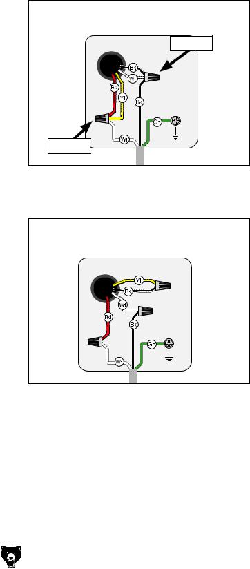
1.disCONNECT MACHINE FROM POWER!
2.Remove the 5-15 plug from the cord.
3.Remove the two wire nuts from the wires shown in Figure 4.
Motor
Pre-wired for 110V
Remove
Ground
Remove
Figure 4. Motor pre-wired for 110V.
4.re-wire the motor as shown in Figure 4.
Motor Rewired for 220V
Ground
Figure 5. Motor rewired for 220V.
5.Tighten all wire nuts and secure them with electrical tape so they cannot vibrate loose during motor operation.
6.Install the 6-15 plug on the power cord per the plug manufacturer's instructions.
G0555LX (Mfg. Since 3/13) |
-11- |
SECTION 3: Set Up
Set Up Safety
This machine presents serious injury hazards to untrained users. Read through this entire manual to become familiar with the controls and operations before starting the machine!
Wear safety glasses during the entire set up process!
This machine and its components are very heavy. Get lifting help or use power lifting equipment such as a forklift to move heavy items.
Needed for Setup
The following are needed to complete the setup process, but are not included with your machine.
Description |
Qty |
|
• |
Additional People........................ |
As Needed |
• |
safety Glasses............................................ |
1 |
• |
Disposable Shop Rags............... |
As Needed |
• |
Cleaner/Degreaser...................... |
As Needed |
• |
level............................................................ |
1 |
• |
hex Wrench 5mm....................................... |
1 |
• Wrench or Socket 10mm............................ |
2 |
|
• Wrench or Socket 13mm............................ |
2 |
|
Unpacking
Your machine was carefully packaged for safe transportation. Remove the packaging materials from around your machine and inspect it. If you discover the machine is damaged, please immediately call us at (570) 546-9663 for advice.
Save the containers and all packing materials for possible inspection by the carrier or its agent.
Otherwise, filing a freight claim can be difficult.
When you are completely satisfied with the condition of your shipment, inventory the contents.
SUFFOCATION HAZARD! Keep children and pets away from plastic bags or packing materials shipped with this machine. Discard immediately.
-12- |
G0555LX (Mfg. Since 3/13) |

Inventory
The following is a list of items shipped with your machine. Before beginning setup, lay these items out and inventory them.
If any non-proprietary parts are missing (e.g. a nut or a washer), we will gladly replace them; or for the sake of expediency, replacements can be obtained at your local hardware store.
Inventory (see Figure 6) |
Qty |
|
A. |
Table .......................................................... |
1 |
B. |
Saw Blade 931⁄2" x 3⁄8" x 6 TPI.................... |
1 |
C. |
Bandsaw Body............................................ |
2 |
D. |
Trunnion Base............................................. |
1 |
E. |
Front Fence Rail.......................................... |
1 |
F. |
Rear Fence Rail.......................................... |
1 |
G. |
Miter Gauge Assembly................................ |
1 |
H. |
Fence Assembly......................................... |
1 |
I. |
Trunnion Lock Knobs.................................. |
2 |
J. |
Upper Stand Braces................................... |
2 |
K. |
Stand Top.................................................... |
1 |
L. |
Stand Sides................................................. |
2 |
M. |
Lower Stand Braces.................................... |
2 |
N. |
Hardware Bag............................................. |
1 |
|
—Table Insert.............................................. |
1 |
|
—Hex Bolts 5⁄16"-18 x 11⁄2" (Bandsaw)......... |
4 |
|
—Hex Nuts 5⁄16"-18 (Bandsaw).................... |
4 |
|
—Lock Washers 5⁄16" (Bandsaw)................. |
4 |
|
—Flat Washers 5⁄16" (Bandsaw).................. |
8 |
|
—Cap Screws 1⁄4"-20 x 5⁄8" (Fence)............. |
2 |
|
—Hex Bolts 1⁄4"-20 x 3⁄4" (Fence)................. |
2 |
|
—Flat Washers 1⁄4" (Fence)......................... |
2 |
|
—Hex Bolts 1⁄4"-20 x 5⁄8" (Stand)............... |
16 |
|
—Flat Washers 1⁄4" (Stand)....................... |
16 |
|
—Flange Nuts (Stand).............................. |
16 |
|
—Stand Feet 3⁄8"-16 x 2" (Stand)................ |
4 |
|
—Carriage Bolts 5⁄16"-18 x 5⁄8" (Stand)......... |
8 |
|
—Flange Nuts 5⁄16"-18 (Stand)..................... |
8 |
|
—Hex Nuts 3⁄8"-16 (Stand Feet).................. |
8 |
|
—Flat Washer 3⁄8" (Stand Feet).................. |
8 |
|
—Combo Wrench 10 x 12mm..................... |
1 |
|
—Hex Wrench 5mm................................... |
1 |
A
C
B
|
D |
E |
|
|
|
|
|
F |
|
|
G |
I |
|
H |
J
K
L
M |
N |
Figure 6. Main components inventory.
NOTICE
If you cannot find an item on this list, carefully check around/inside the machine and packaging materials. Often, these items get lost in packaging materials while unpacking or they are pre-installed at the factory.
G0555LX (Mfg. Since 3/13) |
-13- |

Cleanup
The unpainted surfaces of your machine are coated with a heavy-duty rust preventative that prevents corrosion during shipment and storage. This rust preventative works extremely well, but it will take a little time to clean.
Be patient and do a thorough job cleaning your machine. The time you spend doing this now will give you a better appreciation for the proper care of your machine's unpainted surfaces.
There are many ways to remove this rust preventative, but the following steps work well in a wide variety of situations. Always follow the manufacturer’s instructions with any cleaning product you use and make sure you work in a well-ventilated area to minimize exposure to toxic fumes.
Before cleaning, gather the following:
•Disposable Rags
•Cleaner/degreaser (WD•40 works well)
•Safety glasses & disposable gloves
•Plastic paint scraper (optional)
Basic steps for removing rust preventative:
1.Put on safety glasses.
2.Coat the rust preventative with a liberal amount of cleaner/degreaser, then let it soak for 5–10 minutes.
3.Wipe off the surfaces. If your cleaner/degreaser is effective, the rust preventative will wipe off easily. If you have a plastic paint scraper, scrape off as much as you can first, then wipe off the rest with the rag.
4.Repeat Steps 2–3 as necessary until clean, then coat all unpainted surfaces with a quality metal protectant to prevent rust.
-14-
Gasoline or products with low flash points can explode or cause fire if used to clean machinery. Avoid cleaning with these products.
Many cleaning solvents are toxic if concentrated amounts are inhaled. Only work in a well-venti- lated area.
NOTICE
Avoid chlorine-based solvents, such as acetone or brake parts cleaner, that may damage painted surfaces. Test all cleaners in an inconspicuous area before using to make sure they will not damage paint.
G0555LX (Mfg. Since 3/13)
Site Considerations
Weight Load
Refer to the Machine Data Sheet for the weight of your machine. Make sure that the surface upon which the machine is placed will bear the weight of the machine, additional equipment that may be installed on the machine, and the heaviest workpiece that will be used. Additionally, consider the weight of the operator and any dynamic loading that may occur when operating the machine.
Space Allocation
Consider the largest size of workpiece that will be processed through this machine and provide enough space around the machine for adequate operator material handling or the installation of auxiliary equipment. With permanent installations, leave enough space around the machine to open or remove doors/covers as required by the maintenance and service described in this manual.
See below for required space allocation.
Children or untrained people may be seriously injured by this machine. Only install in an access restricted location.
Physical Environment
The physical environment where the machine is operated is important for safe operation and longevity of machine components. For best results, operate this machine in a dry environment that is free from excessive moisture, hazardous chemicals, airborne abrasives, or extreme conditions. Extreme conditions for this type of machinery are generally those where the ambient temperature range exceeds 41°–104°F; the relative humidity range exceeds 20–95% (non-condensing); or the environment is subject to vibration, shocks, or bumps.
Electrical Installation
Place this machine near an existing power source. Make sure all power cords are protected from traffic, material handling, moisture, chemicals, or other hazards. Make sure to leave access to a means of disconnecting the power source or engaging a lockout/tagout device, if required.
Lighting
Lighting around the machine must be adequate enough that operations can be performed safely. Shadows, glare, or strobe effects that may distract or impede the operator must be eliminated.
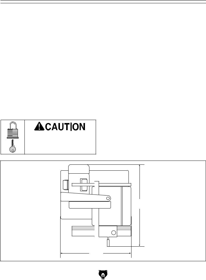
30"
27"
Figure 7. Minimum working clearances.
G0555LX (Mfg. Since 3/13) |
-15- |

Assembly
Some sheet metal parts may have sharp edges that can cause minor cuts. Please use care while handling them.
The bandsaw is heavy and awkward to lift onto the stand. Get assistance from another person when lifting.
To assemble the bandsaw:
1.lay one stand side flat on a piece of cardboard to prevent scratching the paint, then
attach the upper and lower stand braces to one side, as shown in Figure 8, with (8) 1⁄4"-20 x 5⁄8" hex bolts, (8) 1⁄4" flat washers, and
(8) 1⁄4"-20 flange nuts.
Note: Only hand-tighten the stand fasteners during these initial steps. Once the stand is completely assembled you will be instructed to fully tighten all fasteners.
Upper |
Lower |
|
Stand Brace |
||
Stand Brace |
||
|
 x 8
x 8
 Stand Side
Figure 8. Upper and lower stand braces attached to the stand side.
2.attach the remaining stand side to the assembly, as shown in Figure 9, with (8) 1⁄4"-20 x 5⁄8" hex bolts, (8) 1⁄4" flat washers, and (8) 1⁄4"-20 flange nuts.
Figure 9. Second stand side attached.
3.install the stand feet, as shown in Figure 10, in the bottom of the stand assembly, using a 3⁄8"-16 x 2" stand foot, (2) 3⁄8"-16 hex nuts and (2) 3⁄8" flat washers on each foot in the sequence shown.
Note: Adjust the feet so that they are approximately the same height—this will make leveling the stand easier in a later step.
Foot |
Hex Nut |
Flat |
Washer |
Flat |
Washer |
Hex Nut |
Figure 10. Stand foot installed (1 of 4).
-16- |
G0555LX (Mfg. Since 3/13) |

4.Turn the stand assembly upright and attach the top, as shown in Figure 11, with (8) 5⁄16"- 18 x 5⁄8" carriage bolts and (8) 5⁄16"-18 flange nuts.
x 8
Figure 11. Stand top attached.
5.square up the stand components and fully tighten all the fasteners.
6.place the level on top of the stand assembly, as shown in Figure 12, then adjust the feet up or down to make the stand top level from side to side and front to back. Make sure that both hex nuts on the feet are tight against the stand assembly so they will not move.
Figure 12. Leveling the stand.
G0555LX (Mfg. Since 3/13)
7.With the help of other people, lift the bandsaw assembly onto the stand and align the mounting holes. Have one person hold the bandsaw in place to keep it from fall until you can complete the next step.
8.secure the bandsaw assembly to the stand with (4) 5⁄16"-18 x 11⁄2" hex bolts, (4) 5⁄16" lock washers, (8) 5⁄16" flat washers, and (4) 5⁄16"-18 hex nuts, as shown in Figure 13.
 x 4
x 4
Figure 13. Bandsaw assembly attached to the stand.
9.position the table trunnion on the bandsaw, as shown in Figure 14, then secure it with the
(2) 5⁄16"-18 x 11⁄4" hex bolts and (2) 5⁄16" lock washers.
x 2 |
Trunnion |
Figure 14. Trunnion installed.
-17-
10.line up the table slot with the blade, then position the table so that the blade is in the center cut-out.
11.rotate the table so that the table slot faces to the right, then insert the table bolts through the mounting holes in the trunnion base, as shown in Figure 15.
Table
 Table Trunnion
 Trunnion Base
Trunnion Bolt
Figure 15. Installing the table onto the trunnion base.
12.secure the table by fully threading the two trunnion lock knobs onto the table bolts.
13.attach the rear fence rail to the rear of the table with (2) 1/4"-20 x 5⁄8" cap screws, as shown in Figure 16.
Rear Fence
Rail
x 2
Figure 16. Installing rear fence rail.
14.Attach the front fence rail shown in Figure 17, with (2) 1⁄4"-20 x 3⁄4" hex bolts and 1⁄4" flat washers.
Front Fence |
x 2 |
|
Rail |
||
|
Figure 17. Installing front fence rail.
15.Pull the fence handle up and place the fence on the front fence rail, as shown in
Figure 18.
Figure 18. Installing fence onto rails.
-18- |
G0555LX (Mfg. Since 3/13) |
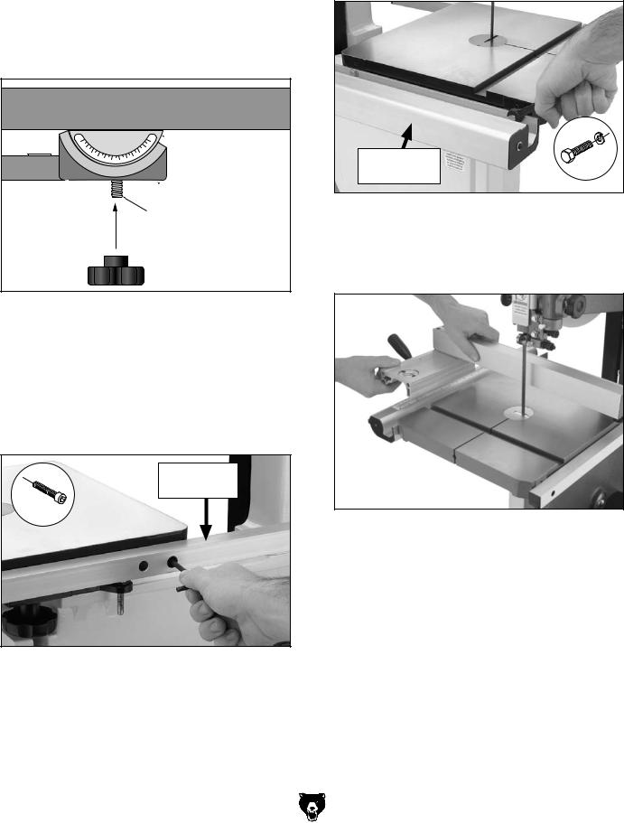
16.Thread the M6-1 hex nut onto the fence rail pad, then thread it into the rear underside of the fence (see Figure 19) so that the fence rests the same height above the table along its full length. Tighten the hex nut against the fence to secure the setting.
Rail Pad
Figure 19. Fence rail pad installed.
17.Install the table insert and table pin, as show in Figure 20.
Important: Make sure you re-install the table pin. This pin keeps the table surfaces on either side of the slot even with the changes in operating pressures and temperature changes.
Figure 20. Table pin and insert installed.
G0555LX (Mfg. Since 3/13)
Adjustment
Overview
The bandsaw is one of the most versatile woodworking machines. As such it has multiple components that must be properly adjusted for the best cutting results.
For safety reasons some adjustments and test operations must be performed before performing other necessary adjustments. Below is an overview of all the adjustments and the order in which they should be performed.
Adjustment procedures include:
•blade Tracking
•dust Collection
•power Connection
•test Run
•tension Blade
•adjusting Blade Support Bearings
•adjusting Blade Guide Bearings
•table Tilt Calibration
•aligning Table
•aligning Fence
-19-
 Loading...