


20'' PLANER
MODEL G1033
INSTRUCTION MANUAL
COPYRIGHT © 1990 BY GRIZZLY INDUSTRIAL, INC.
WARNING: NO PORTION OF THIS MANUAL MAY BE REPRODUCED IN ANY SHAPE OR FORM WITHOUT THE WRITTEN APPROVAL OF GRIZZLY INDUSTRIAL, INC.
REVISED APRIL, 1999. PRINTED IN U.S.A.

|
Table Of Contents |
|
|
|
PAGE |
1. |
SAFETY |
|
|
SAFETY RULES FOR POWER TOOLS .................................................................................. |
2-3 |
|
ADDITIONAL SAFETY INSTRUCTIONS FOR PLANERS .......................................................... |
4 |
2. |
CIRCUIT REQUIREMENTS |
|
|
220V OPERATION ...................................................................................................................... |
5 |
|
FUSING ........................................................................................................................................ |
5 |
|
GROUNDING................................................................................................................................ |
5 |
|
EXTENSION CORDS .................................................................................................................. |
5 |
3. |
INTRODUCTION |
|
|
COMMENTARY ............................................................................................................................ |
6 |
|
UNPACKING ................................................................................................................................ |
7 |
|
PARTS INVENTORY .................................................................................................................... |
7 |
|
CLEAN UP .................................................................................................................................... |
8 |
|
SITE CONSIDERATIONS ............................................................................................................ |
8 |
4. |
ASSEMBLY |
|
|
OVERVIEW .................................................................................................................................. |
9 |
|
EXTENSION ROLLERS .............................................................................................................. |
9 |
|
HANDWHEEL .............................................................................................................................. |
9 |
|
DUST HOOD .............................................................................................................................. |
10 |
|
SWITCH...................................................................................................................................... |
10 |
|
KNIFE SETTING JIG .................................................................................................................. |
11 |
5. |
ADJUSTMENTS |
|
|
CHAIN ADJUSTMENT................................................................................................................ |
12 |
|
TABLE ADJUSTMENT .............................................................................................................. |
12 |
|
CHAIN DRIVE ............................................................................................................................ |
13 |
|
BED ROLLERS .......................................................................................................................... |
14 |
|
KNIFE INSPECTION .................................................................................................................. |
15 |
|
KNIFE ADJUSTMENT ................................................................................................................ |
15 |
|
FEED ROLLER SPEED.............................................................................................................. |
16 |
|
ROLLER ADJUSTMENT ...................................................................................................... |
16-17 |
|
SPRING TENSION .................................................................................................................... |
17 |
|
CHIP BREAKER ........................................................................................................................ |
18 |
|
PRESSURE BAR........................................................................................................................ |
18 |
|
CHIP DEFLECTOR .................................................................................................................... |
19 |
|
STATIC CHAIN ADJUSTER ...................................................................................................... |
19 |
|
SCALE ADJUSTMENT .............................................................................................................. |
20 |
|
ANTI-KICKBACK FINGERS ...................................................................................................... |
20 |
6. |
OPERATIONS |
|
|
TEST RUN .................................................................................................................................. |
21 |
|
OPERATIONAL TIPS ................................................................................................................ |
21 |
|
WOOD CHARACTERISTICS .................................................................................................... |
22 |
7.MAINTENANCE
|
GENERAL .................................................................................................................................. |
23 |
|
KNIVES ...................................................................................................................................... |
23 |
|
LUBRICATION............................................................................................................................ |
24 |
|
BELT TENSION .......................................................................................................................... |
25 |
|
BELT ALIGNMENT .................................................................................................................... |
25 |
8. |
CLOSURE |
|
|
MACHINE DATA ........................................................................................................................ |
27 |
|
TROUBLESHOOTING................................................................................................................ |
28 |
|
PARTS BREAKDOWN AND PARTS LISTS ........................................................................ |
29-35 |
|
ADJUSTMENT BLOCK PATTERN ............................................................................................ |
36 |
|
WIRING DIAGRAM .................................................................................................................... |
37 |
|
WARRANTY AND RETURNS .................................................................................................... |
38 |
G1033 20" Planer |
-1- |

SECTION 1: SAFETY
For Your Own Safety Read Instruction Manual Before Operating This Equipment
The purpose of safety symbols is to attract your attention to possible hazardous conditions. This manual uses a series of symbols and signal words which are intended to convey the level of importance of the safety messages. The progression of symbols is described below. Remember that safety messages by themselves do not eliminate danger and are not a substitute for proper accident prevention measures.
|
|
|
|
|
|
|
|
Indicates an imminently hazardous situation which, if not |
|
|
|
|
|
|
|
|
avoided, WILL result in death or serious injury. |
|
|
|
|
|
|
|
|
Indicates a potentially hazardous situation which, if not |
|
|
|
|
|
|
|
|
|
|
|
|
|
|
|
|
|
|
|
|
|
|
|
|
|
|
avoided, COULD result in death or serious injury. |
|
|
|
|
|
|
|
|
|
|
|
|
|
|
|
|
|
Indicates a potentially hazardous situation which, if not |
|
|
|
|
|
|
|
||
|
|
|
|
|
|
|
|
avoided, MAY result in minor or moderate injury. It may also |
|
|
|
|
|
|
|
|
be used to alert against unsafe practices. |
|
|
|
|
|
|
|
||
|
|
|
|
|
|
|
|
|
|
NOTICE |
|
This symbol is used to alert the user to useful information |
|||||
|
|
about proper operation of the equipment. |
||||||
|
|
|
|
|
|
|
|
|
Safety Instructions For Power Tools
1.KEEP GUARDS IN PLACE and in working order.
2.REMOVE ADJUSTING KEYS AND WRENCHES. Form habit of checking to see that keys and adjusting wrenches are removed from tool before turning on.
3.KEEP WORK AREA CLEAN. Cluttered areas and benches invite accidents.
4.DON’T USE IN DANGEROUS ENVIRONMENT. Don’t use power tools in damp or wet locations, or where any flammable or noxious fumes may exist. Keep work area well lighted.
5.KEEP CHILDREN AND VISITORS AWAY. All children and visitors should be kept a safe distance from work area.
6.MAKE WORK SHOP CHILD PROOF with padlocks, master switches, or by removing starter keys.
7.DON’T FORCE TOOL. It will do the job better and safer at the rate for which it was designed.
8.USE RIGHT TOOL. Don’t force tool or attachment to do a job for which it was not designed.
-2- |
G1033 20" Planer |

Safety Instructions For Power Tools
9.USE PROPER EXTENSION CORD. Make sure your extension cord is in good condition. Conductor size should be in accordance with the chart below. The amperage rating should be listed on the motor or tool nameplate. An undersized cord will cause a drop in line voltage resulting in loss of power and overheating. Your extension cord must also contain a ground wire and plug pin. Always repair or replace extension cords if they become damaged.
Minimum Gauge for Extension Cords
|
|
LENGTH |
|
||
AMP RATING |
25ft |
|
50ft |
|
100ft |
0-6 |
18 |
|
16 |
|
16 |
7-10 |
18 |
|
16 |
|
14 |
11-12 |
16 |
|
16 |
|
14 |
13-16 |
14 |
|
12 |
|
12 |
17-20 |
12 |
|
12 |
|
10 |
21-30 |
10 |
|
10 |
|
No |
|
|
|
|
|
|
10.WEAR PROPER APPAREL. Do not wear loose clothing, gloves, neckties, rings, bracelets, or other jewelry which may get caught in moving parts. Non-slip footwear is recommended. Wear protective hair covering to contain long hair.
11.ALWAYS USE SAFETY GLASSES. Also use face or dust mask if cutting operation is dusty. Everyday eyeglasses only have impact resistant lenses, they are NOT safety glasses.
12.SECURE WORK. Use clamps or a vise to hold work when practical. It’s safer than using your hand and frees both hands to operate tool.
13.DON’T OVERREACH. Keep proper footing and balance at all times.
14.MAINTAIN TOOLS WITH CARE. Keep tools sharp and clean for best and safest performance. Follow instructions for lubricating and changing accessories.
15.DISCONNECT TOOLS before servicing and changing accessories, such as blades, bits, cutters, and the like.
16.REDUCE THE RISK OF UNINTENTIONAL STARTING. Make sure switch is in off position before plugging in.
17.USE RECOMMENDED ACCESSORIES.
Consult the owner’s manual for recommended accessories. The use of improper accessories may cause risk of injury.
18.CHECK DAMAGED PARTS. Before further use of the tool, a guard or other part that is damaged should be carefully checked to determine that it will operate properly and perform its intended function. Check for alignment of moving parts, binding of moving parts, breakage of parts, mounting, and any other conditions that may affect its operation. A guard or other part that is damaged should be properly repaired or replaced.
19.NEVER LEAVE TOOL RUNNING UNATTENDED. TURN POWER OFF. Don’t leave tool until it comes to a complete stop.
G1033 20" Planer |
-3- |
Additional Safety Instructions For Planers
1.Ensure that the machine sits firmly on the floor before use. Any “wobbles” must be corrected by shimming or blocking before operation.
2.This machine is not designed to process any other material except wood.
3.Never position fingers or thumbs near the infeed roller.
4.Long stock should always be fully supported by some type of support fixture.
5.Do not operate planer with dull or damaged knives.
6.Ensure that the planer is properly adjusted before using.
7.Do not remove excessive amounts of wood in a single pass.
8.Inspect your stock before planing. Reject stock with defects and foreign material
9.Do not attempt to remove jams until power is disconnected and all moving parts have come to a complete stop.
10.Provide adequate infeed and outfeed space for operating the planer.
11.Do not plane wood less than 12" long and 1⁄4" thick.
12.Do not plane lumber with loose knots or knots that may become loose during planing.
Like all power tools, there is danger associated with the Model G1033 20" Planer. Accidents are frequently caused by lack of familiarity or failure to pay attention. Use this tool with respect and caution to lessen the possibility of operator injury. If normal safety precautions are overlooked or ignored serious personal injury may occur.
No list of safety guidelines can be complete. Every shop environment is different. Always consider safety first, as it applies to your individual working conditions. Use this and other machinery with caution and respect. Failure to do so could result in serious personal injury, damage to equipment or poor work results.
Operating this equipment has the potential to propel debris into the air which can cause eye injury. Always wear safety glasses or goggles when operating equipment. Everyday glasses or reading glasses only have impact resistant lenses, they are not safety glasses. Be certain the safety glasses you wear meet the appropriate standards of the American National Standards Institute (ANSI).
-4- |
G1033 20" Planer |

SECTION 2: CIRCUIT REQUIREMENTS
220V Operation |
|
Grounding |
|
|
|
|
|
|
The 3 HP G1033 Planer motor is wired to operate at 220V only. A 220V plug that matches your 220V receptacle must attach to the end of the power cord. Plugs and receptacles can be purchased at your local hardware store or home center. When connecting to 220V, ensure that the electrical circuit is in fact a 220V circuit. Contact your local electrical contractor if uncertain about converting to 220V operation. A wiring diagram for the motor and switch is provided at the back of this manual should more detail be needed.
When operating at 220V, we recommend using a NEMA-style 6-30 plug and outlet. See Figure 1. You may also “hard-wire” the planer directly to your panel, provided you place a disconnect switch near the machine.
In the event of an electrical short, grounding reduces the risk of electric shock by providing a path of least resistance to disperse electric current. This tool is equipped with a power cord having an equipment-grounding conductor. The outlet must be properly installed and grounded in accordance with all local codes and ordinances.
This equipment must be grounded. Please ensure that this machine is continuously grounded from the motor to the machine frame and then to a known ground. Verify that any existing electrical outlet and circuit you intend to plug into is actually grounded. If it is not, it will be necessary to run a separate 12 A.W.G. copper grounding wire from the outlet to a known ground. Under no circumstances should the grounding pin from any three-pronged plug be removed. Serious injury may occur.
Figure 1. Twist-lock style 30A connector.
Fusing
The Model G1033 should be fused at 30 amps. Fusing at amperage ratings higher than 30 amps will not adequately protect the motor. You are cautioned that equipment that is returned to us for service that shows evidence of being overfused will be repaired or replaced totally at the customer’s expense, regardless of the present warranty status.
Extension Cords
We do not recommend the use of extension cords on 220V equipment. It is much better to arrange the placement of your equipment and the installed wiring to eliminate the need for extension cords. Should it be necessary to use an extension make sure the cord is rated Hard Service (grade S) or better. Refer to the chart in Section 1: Safety Instructions to determine the minimum gauge for the extension cord. The extension cord must also contain a ground wire and plug pin. Always repair or replace extension cords when they become worn or damaged.
|
|
|
|
|
|
|
|
|
|
|
|
|
|
|
|
|
|
|
|
|
|
|
|
|
|
|
|
|
|
|
|
|
|
|
|
|
|
|
|
|
|
G1033 20" Planer |
|
-5- |
||||
|
||||||

SECTION 3: INTRODUCTION
Commentary
We are proud to offer the Grizzly Model G1033 20" Planer. The Model G1033 is part of a growing Grizzly family of fine woodworking machinery. When used according to the guidelines set forth in this manual, you can expect years of troublefree, enjoyable operation and proof of Grizzly’s commitment to customer satisfaction.
The Model G1033 is designed for heavy-duty professional use. It features a powerful 3HP, 220V/240V single-phase motor, four-knife cutterhead, 2-speed automatic feed, precision-ground table and a both a chipbreaker and a pressure bar to support the stock as it moves through the machine.
A number of optional accessories for the Model G1033 are available through the Grizzly catalog. They include a heavy-duty mobile base, roller stands, replacement knives and Planer Pal® planer jigs, which are invaluable when setting up or adjusting your planer’s cutting knives.
We are also pleased to provide this manual with the Model G1033. It was written to guide you through assembly, review safety considerations, and cover general operating procedures. It represents our effort to produce the best documentation possible. If you have any comments regarding this manual, please write to us at the address below:
Grizzly Industrial, Inc.
C/O Technical Documentation
P.O. Box 2069
Bellingham, WA 98227-2069
Most importantly, we stand behind our machines. If you have any service questions or parts requests, please call or write us at the location listed below.
Grizzly Industrial, Inc.
1203 Lycoming Mall Circle
Muncy, PA 17756
Phone: (570) 546-9663
Fax: (800) 438-5901 E-Mail: techsupport@grizzly.com Web Site: http://www.grizzly.com
The specifications, drawings, and photographs illustrated in this manual represent the Model G1033 as supplied when the manual was prepared. However, owing to Grizzly’s policy of continuous improvement, changes may be made at any time with no obligation on the part of Grizzly. Whenever possible, though, we send manual updates to all owners of a particular tool or machine. Should you receive one, we urge you to insert the new information with the old and keep it for reference.
To operate this, or any power tool, safely and efficiently, it is essential to become as familiar with its characteristics as possible. The time you invest before you begin to use your Model G1033 will be time well spent. DO NOT operate this machine until you are completely familiar with the contents of this manual. Make sure you read and understand all of the safety procedures. If you do not understand something, DO NOT operate the machine.
-6- |
G1033 20" Planer |
Unpacking
This planer is shipped from the factory in a carefully packed carton. If you find the machine to be damaged after you’ve signed for delivery and the truck and driver are already gone, you will need to file a freight claim with the carrier. Save the containers and all packing materials for inspection by the carrier or their agent. Without the packing materials, filing a freight claim can be difficult. If you need advice regarding this situation, please call us immediately.
The Model G1033 is a heavy machine (770 lbs. shipping weight). DO NOT over-exert yourself while unpacking or moving your machine – get assistance. In the event that your planer must be moved up or down a flight of stairs, be sure that the stairs are capable of supporting the combined weight of people and the machine. Failure to use care while assembling or moving could result in serious personal injury.
Parts Inventory
Take a quick inventory of the parts and put them aside for assembly later. After all the parts have been removed from the container, you should have:
•Planer Unit
•Dust Hood
•Hand Wheel
•Starter Switch
•Rollers (2)
•Knife Gauge
•Bolt Bag
(2)12mm Snap Rings
(2)10mm Flat Washers
(8)M10x1.5 Hex Bolts
(8)6mm Flat Washers
(4)Snap Rings
(6)M10x1.5 Hex Bolts
(6)Flat Washers
In the event that any non-proprietary parts are missing (e.g. a nut or a washer), we would be glad to replace them, or, for the sake of expediency, replacements can be obtained at your local hardware store.
NOTICE
A full parts list and breakdown can be found toward the end of this manual. For easier assembly, or to identify missing parts, please refer to the detailed illustrations at the end of the manual.
|
|
|
|
|
|
|
|
|
|
|
|
G1033 20" Planer |
-7- |
||
Clean Up
The unpainted surfaces are coated with a waxy oil to protect it from corrosion during shipment. Remove this protective coating with with a solvent cleaner or citrus-based degreaser. Avoid chlorine-based solvents as they may damage painted surfaces should they come in contact. Always follow the usage instructions on the product you choose for clean up.
Many of the solvents commonly used to clean machinery can be highly flammable, and toxic when inhaled or ingested. Always work in well-ventilated areas far from potential ignition sources when dealing with solvents. Use care when disposing of waste rags and towels to be sure they do not create fire or environmental hazards. Keep children and animals safely away when cleaning and assembling this machine.
Do not use gasoline or other petroleumbased solvents to remove this protective coating. These products generally have low flash points which makes them extremely flammable. A risk of explosion and burning exists if these products are used. Serious personal injury may occur.
Some die-cut metal parts may have sharp edges (called “flashing”) on them after they are formed. Please examine the edges of all die-cut metal parts before handling them. Failure to do so could result in injury.
Site Considerations
FLOOR LOAD
Your G1033 Planer represents a large weight load in a small footprint. Most commercial floors are suitable for the Model G1033. Some residential floors may require additional build up to support both machine and operator.
WORKING CLEARANCES
Working clearances can be thought of as the distances between machines and obstacles that allow safe operation of every machine without limitation. Consider existing and anticipated machine needs, size of material to be processed through each machine, and space for auxiliary stands and/or work tables. Also consider the relative position of each machine to one another for efficient material handling. Be sure to allow yourself sufficient room to safely run your machines in any foreseeable operation.
LIGHTING AND OUTLETS
Lighting should be bright enough to eliminate shadow and prevent eye strain. Electrical circuits should be dedicated or large enough to handle combined motor amp loads. Outlets should be located near each machine so power or extension cords are not obstructing high-traffic areas. Be sure to observe local electrical codes for proper installation of new lighting, outlets, or circuits.
Make your shop “child safe”. Ensure that your workplace is inaccessible to youngsters by closing and locking all entrances when you are away. Never allow visitors in your shop when assembling, adjusting or operating equipment.
|
|
|
|
|
|
|
|
|
|
|
|
|
|
|
|
|
|
|
|
G1033 20" Planer |
|
|
|
|
|
|
|
-8- |
|
|
|
|
|
|
|
|
|
|
|
SECTION 4: ASSEMBLY
Overview
Most of your G1033 Planer has been assembled at the factory, but some parts must be assembled or installed after delivery. We have organized the assembly process into steps. Please follow along in the order presented here.
TOOLS REQUIRED: Most of the tools required for assembly are included with the planer. However, you will also need a Phillips® and regular screwdriver, metric wrenches, as well as a feeler gauge for adjustments.
Extension Rollers
The Model G1033 is supplied with extension rollers on both the infeed and outfeed ends of the table. The roller assemblies are identical for both infeed and outfeed. To attach the extension rollers:
1.Attach an extension bar to the end of each roller and secure with the 12mm snap rings provided.
2.The assembled extension rollers attach to the ends of the planer’s table. Match the tapped holes on the side of the table to the extension bars and attach with the M10 x 1.5 Hex Bolts and washers provided. See
Figure 2.
3.Before final tightening, run a straight edge across the table and past each roller. Position the rollers flush with the table and tighten the Hex Bolts securely.
Extension
 Mounting Bolts
Figure 2. Extension roller attachment.
Hand Wheel
The hand wheel operates the chain driven system which raises and lowers the table to control cutting depth. To attach the hand wheel:
1.Place the handwheel on the worm gear shaft and secure with hex nut and washer provided. See Figure 3.
2.Attach the handle to the handwheel and tighten hex nut.
Figure 3. Attaching handwheel.
|
|
|
|
|
|
|
|
G1033 20" Planer |
|
-9- |
|
|
|||
Dust Hood |
|
Switch |
|
|
|
|
|
|
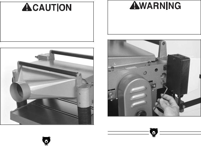
The G1033 features a dust hood with a 5'' dust port. It is only to be used in conjunction with a dust collection system. Install the dust hood as follows:
1.Match the mounting holes on the dust hood with the tapped holes on the outfeed end of the cutterhead casting.
2.Using the six M6-1.0 Hex bolts provided, secure the dust hood to the cutterhead casting. See Figure 4.
See note regarding the use of a dust collector and chip deflector adjustment in the adjustment section of this manual.
DO NOT attach the dust hood if you do not intend to connect the Model G1033 to a dust collection system. Accumulated wood chips could cause a malfunction, resulting in personal injury or damage to the planer.
The magnetic ON/OFF switch supplied with the Planer is pre-wired to the motor. The remaining step requires connecting the switch to the planer's head casting. To attach the switch:
1.Align the holes on the flanges at the back of the switch box with the tapped holes on the front left corner of the head casting.
2.Using the socket head cap screws provided, attach the switch box assembly to the head casting. See Figure 5.
The G1033 is shipped without a plug. Now would be a good time to attach the appropriate plug specified in Section 2: Circuit Requirements.
Do not attempt to make any adjustments to this machine or perform routine maintenance without unplugging it from its power source. Serious injury could result.
Figure 5. Attaching switch.
Figure 4. Dust hood in place.
|
|
|
|
|
|
|
|
-10- |
|
|
G1033 20" Planer |
|
|
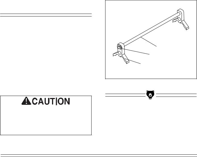
Knife Setting Jig |
|
|
The knife setting jig has been provided to make |
|
|
knife setting quick and easy. See Figure 6. |
|
|
To assemble the knife setting jig: |
|
|
1. Snap one of the E-clips over the notch on |
Jig Rod |
|
|
||
one end of the knife setting rod. |
|
E-clip |
|
|
|
2. Slide the cast aluminum knife setting |
jig |
Jig Bracket |
brackets onto the rod. |
|
|
|
|
|
3. Snap the other E-clip onto the notch at the |
Figure 6. Knife setting jig. |
|
other end of the knife setting jig rod. |
|
|
Planer knives are dangerously sharp. Use extreme caution when working near cutting surfaces. Failure to exercise care while working near knives could result in severe injury.
NOTES
G1033 20" Planer |
-11- |
 Loading...