


MODEL G0704
MILL/DRILL WITH STAND
OWNER'S Manual
Copyright © February, 2010 By Grizzly Industrial, Inc. Revised JUNE, 2011 (JB)
Warning: No portion of this manual may be reproduced in any shape Or form without the written approval of Grizzly Industrial, inc.
(For models manufactured since 09/09) #JB12468 printed in CHINA

This manual provides critical safety instructions on the proper setup, operation, maintenance, and service of this machine/tool. Save this document, refer to it often, and use it to instruct other operators.
Failure to read, understand and follow the instructions in this manual may result in fire or serious personal injury—including amputation, electrocution, or death.
The owner of this machine/tool is solely responsible for its safe use. This responsibility includes but is not limited to proper installation in a safe environment, personnel training and usage authorization, proper inspection and maintenance, manual availability and comprehension, application of safety devices, cutting/sanding/grinding tool integrity, and the usage of personal protective equipment.
The manufacturer will not be held liable for injury or property damage from negligence, improper training, machine modifications or misuse.
Some dust created by power sanding, sawing, grinding, drilling, and other construction activities contains chemicals known to the State of California to cause cancer, birth defects or other reproductive harm. Some examples of these chemicals are:
•Lead from lead-based paints.
•Crystalline silica from bricks, cement and other masonry products.
•Arsenic and chromium from chemically-treated lumber.
Your risk from these exposures varies, depending on how often you do this type of work. To reduce your exposure to these chemicals: Work in a well ventilated area, and work with approved safety equipment, such as those dust masks that are specially designed to filter out microscopic particles.
Table of Contents
INTRODUCTION................................................ |
2 |
Manual Accuracy............................................ |
2 |
Contact Info.................................................... |
2 |
Machine Description....................................... |
2 |
Identification................................................... |
3 |
Electronic Controls Identification.................... |
4 |
SECTION 1: SAFETY........................................ |
8 |
Safety Instructions for Machinery................... |
8 |
Additional Safety for Mill/Drills...................... |
10 |
SECTION 2: POWER SUPPLY....................... |
11 |
SECTION 3: SETUP........................................ |
13 |
Needed for Setup......................................... |
13 |
Unpacking..................................................... |
13 |
Inventory....................................................... |
14 |
Cleanup........................................................ |
15 |
Site Considerations...................................... |
16 |
Moving & Placing Machine........................... |
17 |
Mounting to Shop Floor................................ |
18 |
Assembly...................................................... |
19 |
Drill Chuck Arbor.......................................... |
19 |
Power Connection........................................ |
20 |
Test Run & Spindle Break-in........................ |
21 |
SECTION 4: OPERATIONS............................ |
22 |
Basic Controls.............................................. |
22 |
SECTION 4: OPERATIONS............................ |
24 |
Operation Overview...................................... |
24 |
Digital Readout Unit..................................... |
25 |
Calculating Spindle Speed........................... |
26 |
Spindle Speed and Direction........................ |
27 |
Spindle Height Controls................................ |
28 |
Drill Chuck.................................................... |
29 |
Loading Tooling............................................ |
30 |
Headstock Travel (Z-Axis and Rotation)...... |
31 |
Table Travel.................................................. |
32 |
SECTION 5: ACCESSORIES.......................... |
33 |
SECTION 6: MAINTENANCE......................... |
36 |
Schedule....................................................... |
36 |
Lubrication.................................................... |
36 |
SECTION 7: SERVICE.................................... |
39 |
Troubleshooting............................................ |
39 |
Gibs.............................................................. |
41 |
Leadscrew Backlash..................................... |
42 |
Digital Readout Unit Battery Replacement... |
42 |
Motor Service............................................... |
43 |
SECTION 8: WIRING...................................... |
44 |
Wiring Safety Instructions............................. |
44 |
Wiring Diagram............................................. |
45 |
Electrical Components.................................. |
46 |
SECTION 9: PARTS........................................ |
47 |
Column Breakdown...................................... |
47 |
Column Parts List......................................... |
48 |
Electrical Box Breakdown & Parts List......... |
49 |
Headstock Breakdown.................................. |
50 |
Headstock Parts List.................................... |
51 |
Chip Guard Breakdown & Parts List............ |
52 |
Labels Breakdown & Parts List.................... |
53 |
WARRANTY AND RETURNS......................... |
57 |

INTRODUCTION
Manual Accuracy |
Contact Info |
|
|
|
|
|
|
|
We are proud to offer this manual with your new machine! We've made every effort to be exact with the instructions, specifications, drawings, and photographs of the machine we used when writing this manual. However, sometimes we still make an occasional mistake.
Also, owing to our policy of continuous improvement, your machine may not exactly match the manual. If you find this to be the case, and the difference between the manual and machine leaves you in doubt, check our website for the latest manual update or call technical support for help.
Before calling, find the manufacture date of your machine by looking at the date stamped into the machine ID label (see below). This will help us determine if the manual version you received matches the manufacture date of your machine.
Manufacture Date |
of Your Machine |
For your convenience, we post all available manuals and manual updates for free on our website at www.grizzly.com. Any updates to your model of machine will be reflected in these documents as soon as they are complete.
We stand behind our machines. If you have any questions or need help, use the information below to contact us. Before contacting, please get the serial number and manufacture date of your machine. This will help us help you faster.
Grizzly Technical Support 1203 Lycoming Mall Circle Muncy, PA 17756 Phone: (570) 546-9663 Email: techsupport@grizzly.com
We want your feedback on this manual. What did you like about it? Where could it be improved? Please take a few minutes to give us feedback.
Grizzly Documentation Manager
P.O. Box 2069
Bellingham, WA 98227-2069
Email: manuals@grizzly.com
Machine Description
The mill/drill is used to shape metal and solid workpieces by removing material with the use of a rotating cutting tool.
In milling operations, the cutting tool remains stationary while the workpiece is drawn across it by moving the table.
In drilling operations, the workpiece is held stationary on the table while the cutting tool moves up-and-down with the movement of the spindle and head.
-2- |
Model G0704 (Mfg. since 09/09) |

|
|
Identification |
|
|
|
A |
|
|
B |
|
|
|
|
|
Y |
|
|
C |
|
|
|
|
|
|
X |
|
|
D |
|
|
|
|
|
|
W |
|
|
E |
|
|
|
|
|
|
V |
|
|
D |
|
|
|
|
|
|
|
|
|
F |
|
U |
|
|
|
|
T |
|
|
|
|
S |
|
|
G |
|
R |
|
|
H |
|
|
Q |
|
||
|
|
|
|
|
H |
|
|
|
|
P |
|
|
|
|
I |
|
|
|
|
K |
|
|
|
I |
|
|
|
|
|
O |
|
|
|
J |
|
|
K |
|
|
|
|
|
|
|
|
|
|
L |
|
N |
|
|
M |
|
|
|
|
|
Figure 1. G0704 Identification.
A.Drawbar Cap and Drawbar
B.Vertical (Z-Axis) Handwheel
C.Speed Range Selector Knob
D.Vertical Travel Lock
E.Fine Feed Lock Knob
F.Quill Feed Lever
G.Table
H.Longitudinal (X-Axis) Handwheel
I.Longitudinal Table Stop
J.Table Cross Travel Locks
K.Table Longitudinal Travel Lock
L.Table Center Stop
M.Machine Stand
Model G0704 (Mfg. since 09/09)
N.Storage Access Door
O.Cross (Y-Axis) Handwheel
P.Longitudinal Scale
Q.Drill Chuck
R.Headstock Tilt Scale
S.Chip Guard
T.Quill Lock Lever
U.Fine Feed Knob
V.Digital Readout (Page 4)
W.Control Panel (Page 4)
X.Headstock
Y.Column
-3-
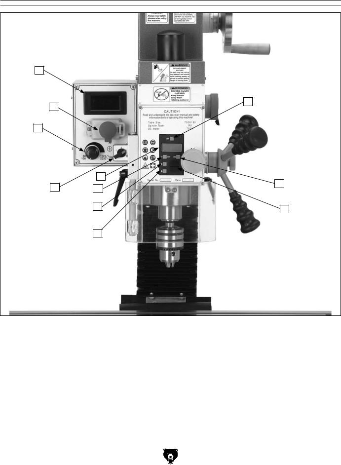
Electronic Controls Identification
A
B
K
J
|
H |
C |
|
I |
G |
||
|
|||
|
F |
D |
|
|
|
||
|
E |
|
Figure 2. G0704 electronic controls identification.
A. |
Spindle RPM Readout |
G. |
IN/MM Unit Selection Button |
B. Spindle Digital Readout OFF Button |
H. |
Spindle Depth Display |
|
C. Digital Readout ON/ZERO Button |
I. |
Spindle Direction Selection Knob |
|
D. Digital Readout Battery Cover & Battery |
J. |
Variable Spindle Speed Knob |
|
E. |
Spindle Depth Display DECREASE Button |
K. |
START/Emergency STOP Buttons |
F.Spindle Depth Display INCREASE Button
-4- |
Model G0704 (Mfg. since 09/09) |

MACHINE DATA
SHEET
Customer Service #: (570) 546-9663 · To Order Call: (800) 523-4777 · Fax #: (800) 438-5901
MODEL G0704 DRILL/MILL WITH STAND
Product Dimensions: |
|
Weight.............................................................................................................................................................. |
265 lbs. |
Width (side-to-side) x Depth (front-to-back) x Height........................................................................... |
38 x 24 x 31 in. |
Footprint (Length x Width)............................................................................................................... |
13-3/8 x 16-1/2 in. |
Shipping Dimensions: |
|
Carton #1 |
|
Type...................................................................................................................................................... |
Plywood |
Content................................................................................................................................................. |
Machine |
Weight.................................................................................................................................................... |
309 lbs. |
Length x Width x Height............................................................................................................. |
28 x 30 x 35 in. |
Carton #2 |
|
Type................................................................................................................................................... |
Cardboard |
Content...................................................................................................................................................... |
Stand |
Weight...................................................................................................................................................... |
77 lbs. |
Length x Width x Height............................................................................................................. |
18 x 15 x 33 in. |
Electrical: |
|
Power Requirement........................................................................................................... |
110V, Single-Phase, 60 Hz |
Minimum Circuit Size........................................................................................................................................ |
15 Amp |
Switch................................................................................................................. |
ON/OFF Buttons with Lockout Cover |
Switch Voltage..................................................................................................................................................... |
110V |
Cord Length............................................................................................................................................................ |
6 ft. |
Cord Gauge................................................................................................................................................... |
18 gauge |
Plug Included.......................................................................................................................................................... |
Yes |
Included Plug Type.................................................................................................................................... |
NEMA 5-15 |
Motors: |
|
Main |
|
Type..................................................................................................................................................... |
Universal |
Horsepower................................................................................................................................................ |
1 HP |
Voltage....................................................................................................................................................... |
110V |
Phase............................................................................................................................................ |
Single-Phase |
Amps........................................................................................................................................................... |
3.2A |
Speed................................................................................................................................................ |
5000 RPM |
Cycle......................................................................................................................................................... |
60 Hz |
Number of Speeds............................................................................................................................................ |
1 |
Power Transfer ................................................................................................................................. |
Gear Drive |
Bearings....................................................................................................... |
Shielded and Permanently Sealed |
Model G0704 (Mfg. since 09/09) |
-5- |

Main Specifications: |
|
Operation Info |
|
Spindle Travel.............................................................................................................................................. |
2 in. |
Longitudinal Table Travel.................................................................................................................... |
18-7/8 in. |
Cross Table Travel................................................................................................................................ |
6-7/8 in. |
Head Travel............................................................................................................................................... |
11 in. |
Head Swivel (Left-to-Right)............................................................................................................... |
+/- 90 deg. |
Maximum Distance Spindle to Column.................................................................................................. |
7-1/2 in. |
Maximum Distance Spindle to Table......................................................................................................... |
13 in. |
Drilling Capacity for Cast Iron................................................................................................................... |
3/4 in. |
Drilling Capacity for Steel......................................................................................................................... |
5/8 in. |
Number of Vertical Spindle Speeds...................................................................................... |
2 Variable Ranges |
Range of Vertical Spindle Speeds................................................................................................ |
50-2250 RPM |
Table Info |
|
Table Length........................................................................................................................................ |
26-5/8 in. |
Table Width......................................................................................................................................... |
7-1/16 in. |
Table Thickness.................................................................................................................................... |
1-3/4 in. |
Number of T-Slots............................................................................................................................................ |
3 |
T-Slots Width............................................................................................................................................ |
1/2 in. |
T-Slots Height........................................................................................................................................... |
5/8 in. |
T-Slots Centers...................................................................................................................................... |
2-1/2 in. |
Stud Size.................................................................................................................................................. |
3/8 in. |
Spindle Info |
|
Spindle Taper............................................................................................................................................... |
R-8 |
Spindle Sleeve Diameter........................................................................................................................ |
2.36 in. |
End Milling Capacity................................................................................................................................. |
3/4 in. |
Face Milling Capacity............................................................................................................................ |
2-1/2 in. |
Drawbar Diameter................................................................................................................................... |
7/16 in. |
Drawbar TPI................................................................................................................................................... |
20 |
Drawbar Length................................................................................................................................. |
9-11/16 in. |
Spindle Bearings......................................................................................................................... |
Tapered Roller |
Construction |
|
Spindle Housing/Quill........................................................................................................................... |
Cast Iron |
Table....................................................................................................................... |
Precision-Ground Cast Iron |
Head.................................................................................................................................................... |
Cast Iron |
Column................................................................................................................................................. |
Cast Iron |
Base..................................................................................................................................................... |
Cast Iron |
Stand.......................................................................................................................................................... |
Steel |
Paint......................................................................................................................................................... |
Epoxy |
Other |
|
Collar Graduations................................................................................................................................ |
0.002 in. |
-6- |
Model G0704 (Mfg. since 09/09) |

Features:
Digital spindle scale reads metric, inches, zero, set, on/off
Forward/reverse switch
Chip guard
Digital display for spindle speed
Dovetail column
Front mounted fine feed knob
Coolant trough
Accessories Included:
Drill chuck 1/16-1/2 in. with B16 taper
Drill chuck arbor B16 x R8
Two T-bolts
Two open-ended combo wrenches
Chuck key
Oil bottle
Extra fuse
Hex wrenches
Standard and Phillips screwdrivers
Tool box
Model G0704 (Mfg. since 09/09) |
-7- |

SECTION 1: SAFETY
For Your Own Safety, Read Instruction Manual Before Operating this Machine
The purpose of safety symbols is to attract your attention to possible hazardous conditions. This manual uses a series of symbols and signal words intended to convey the level of importance of the safety messages. The progression of symbols is described below. Remember that safety messages by themselves do not eliminate danger and are not a substitute for proper accident prevention measures.
|
|
Indicates an imminently hazardous situation which, if not avoided, |
|
|
|
|
|
WILL result in death or serious injury. |
|
|
Indicates a potentially hazardous situation which, if not avoided, |
|
|
|
|
|
COULd result in death or serious injury. |
|
|
|
|
|
Indicates a potentially hazardous situation which, if not avoided, |
|
|
|
|
|
MAY result in minor or moderate injury. It may also be used to alert |
|
|
|
|
|
against unsafe practices. |
NOTICE |
This symbol is used to alert the user to useful information about |
|
proper operation of the machine. |
||
Safety Instructions for Machinery
OWNER’S MANUAL. Read and understand this owner’s manual BEFORE using machine. Untrained users can be seriously hurt.
EYE PROTECTION. Always wear ANSI-approved safety glasses or a face shield when operating or observing machinery to reduce the risk of eye injury or blindness from flying particles. Everyday eyeglasses are not approved safety glasses.
HAzARdOUS dUST. Dust created while using machinery may cause cancer, birth defects, or long-term respiratory damage. Be aware of dust hazards associated with each workpiece material, and always wear a NIOSH-approved respirator to reduce your risk.
WEARING PROPER APPAREL. Do not wear clothing, apparel, or jewelry that can become entangled in moving parts. Always tie back or cover long hair. Wear non-slip footwear to avoid accidental slips which could cause a loss of workpiece control.
HEARING PROTECTION. Always wear hearing protection when operating or observiing loud machinery. Extended exposure to this noise without hearing protection can cause permanent hearing loss.
MENTAL ALERTNESS. Be mentally alert when running machinery. Never operate under the influence of drugs or alcohol, when tired, or when distracted.
-8- |
Model G0704 (Mfg. since 09/09) |
DISCONNECTING POWER SUPPLY.Alwaysdisconnect machine from power supply before servicing, adjusting, or changing cutting tools (bits, blades,cutters,etc.).MakesureswitchisinOFF positionbeforereconnectingtoavoidanunexpectedorunintentionalstart.
APPROVED OPERATION. Untrained operators can be seriously hurt by machinery. Only allow trained or properly supervised people to use machine.Whenmachineisnotbeingused,dis- connectpower,removeswitchkeys,orlock-out machinetopreventunauthorizeduse—especially aroundchildren.Makeworkshopkidproof!
DANGEROUS ENVIRONMENTS. Do not use machinery in wet or rainy locations, cluttered areas,aroundflammables,orinpoorly-litareas. Keep work area clean, dry, and well-lighted to minimizeriskofinjury.
ONLY USE AS INTENDED.Onlyusemachine for its intended purpose. Never modify or alter machineforapurposenotintendedbythemanufacturerorseriousinjurymayresult!
USE RECOMMENDED ACCESSORIES.Consult thisowner’smanualorthemanufacturerforrecommendedaccessories.Usingimproperaccessorieswillincreasetheriskofseriousinjury.
CHILDREN & BYSTANDERS. Keep children andbystandersasafedistanceawayfromwork area.Stopusingmachineifchildrenorbystandersbecomeadistraction.
REMOVE ADJUSTING TOOLS. Never leave adjustmenttools,chuckkeys,wrenches,etc.inor onmachine—especiallynearmovingparts.Verify removalbeforestarting!
SECURING WORKPIECE. When required, use clampsorvisestosecureworkpiece.Asecured workpieceprotectshandsandfreesbothofthem tooperatethemachine.
FEED DIRECTION.Unlessotherwisenoted,feed work against the rotation of blades or cutters. Feedinginthesamedirectionofrotationmaypull yourhandintothecut.
FORCING MACHINERY.Donotforcemachine. Itwilldothejobsaferandbetterattheratefor whichitwasdesigned.
GUARDS & COVERS. Guards and covers can protectyoufromaccidentalcontactwithmoving partsorflyingdebris.Makesuretheyareproperlyinstalled,undamaged,andworkingcorrectly beforeusingmachine.
NEVER STAND ON MACHINE.Seriousinjuryor accidentalcontactwithcuttingtoolmayoccurif machineistipped.Machinemaybedamaged.
STABLE MACHINE. Unexpectedmovementduringoperationsgreatlyincreasestheriskofinjury andlossofcontrol.Verifymachinesarestable/ secure and mobile bases (if used) are locked beforestarting.
AWKWARD POSITIONS. Keep proper footing andbalanceatalltimeswhenoperatingmachine. Donotoverreach!Avoidawkwardhandpositions thatmakeworkpiececontroldifficultorincrease theriskofaccidentalinjury.
UNATTENDED OPERATION. Never leave machinerunningwhileunattended.Turnmachine offandensureallmovingpartscompletelystop beforewalkingaway.
MAINTAIN WITH CARE.Followallmaintenance instructions and lubrication schedules to keep machineingoodworkingcondition.Animproperly maintainedmachinemayincreasetheriskofseriousinjury.
CHECK DAMAGED PARTS. Regularly inspect machine for damaged parts, loose bolts, misadjusted or mis-aligned parts, binding, or any other conditions that may affect safe operation. Alwaysrepairorreplacedamagedormis-adjust- edpartsbeforeoperatingmachine.
EXPERIENCING DIFFICULTIES. If at any time you are experiencing difficulties performing the intended operation, stop using the machine! Contact our Technical Support Department at (570)546-9663.
Model G0704 (Mfg. since 09/09) |
-9- |

Additional Safety for Mill/Drills
UNDERSTANDING CONTROLS. Make sure you understand the use and operation of all controls.
Safety accessories. Always use a chip guard in addition to your safety glasses when milling/drilling to prevent bodily injury.
WORK HOLDING. Before starting the machine, be certain the workpiece has been properly clamped to the table. NEVER hold the workpiece by hand when using the mill/drill.
CHUCK KEY SAFETY. Always remove your chuck key, drawbar wrench, and any service tools immediately after use.
SPINDLE SPEEDS. Select the spindle speed that is appropriate for the type of work and material. Allow the mill/drill to gain full speed before beginning a cut.
POWER DISRUPTION. In the event of a local power outage during use of the mill, drill turn OFF all switches to avoid possible sudden start up once power is restored.
SPINDLE DIRECTION CHANGES. Neverreverse spindle direction while the spindle is turning.
MACHINE CARE AND MAINTENANCE. Never operate the mill/drill with damaged or worn parts. Maintain your mill/drill in proper working condition. Perform routine inspections and maintenance promptly. Put away adjustment tools after use.
STOPPING SPINDLE. DO NOT stop the mill/drill using your hand against the chuck.
BE ATTENTIVE. DO NOT leave the mill/drill running unattended for any reason.
DISCONNECT POWER. Make sure the mill/drill is turned off, disconnected from its power source and all moving parts have come to a complete stop before starting any inspection, adjustment, or maintenance procedure.
AVOIDING ENTANGLEMENT. Keep loose clothing articles such as sleeves, belts or jewelry items away from the spindle. Never wear gloves when operating the mill/drill.
TOOL HOLDING. Always use the proper tools for the material you are machining. Make sure they are held firmly in the proper tool holder for the job.
CLEAN-UP. DO NOT clear chips by hand. Use a brush, and never clear chips while the spindle is turning.
CUTTING TOOL INSPECTION. Inspect drills and end mills for sharpness, chips, or cracks before each use. Replace dull, chipped, or cracked cutting tools immediately. Handle new cutting tools with care. Leading edges are very sharp and can cause lacerations.
EXPERIENCING DIFFICULTIES. If at any time you are experiencing difficulties performing the intended operation, stop using the machine! Contact our Technical Support at (570) 5469663.
No list of safety guidelines can be complete. Every shop environment is different. Like all machines there is danger associated with the Model G0704. Accidents are frequently caused by lack of familiarity or failure to pay attention. Use this machine with respect and caution to lessen the possibility of operator injury. If normal safety precautions are overlooked or ignored, serious personal injury may occur.
-10- |
Model G0704 (Mfg. since 09/09) |

SECTION 2: POWER SUPPLY
Availability
Before installing the machine, consider the availability and proximity of the required power supply circuit. If an existing circuit does not meet the requirements for this machine, a new circuit must be installed. To minimize the risk of electrocution, fire, or equipment damage, installation work and electrical wiring must be done by a qualified electrician in accordance with all applicable codes and standards.
Electrocution, fire, or equipment damage may occur if machine is not correctly grounded and connected to the power supply.
Full-Load Current Rating
The full-load current rating is the amperage a machine draws at 100% of the rated output power. On machines with multiple motors, this is the amperage drawn by the largest motor or sum of all motors and electrical devices that might operate at one time during normal operations.
Full-Load Current Rating at 110V..... 3.2 Amps
The full-load current is not the maximum amount of amps that the machine will draw. If the machine is overloaded, it will draw additional amps beyond the full-load rating.
If the machine is overloaded for a sufficient length of time, damage, overheating, or fire may result— especially if connected to an undersized circuit. To reduce the risk of these hazards, avoid overloading the machine during operation and make sure it is connected to a power supply circuit that meets the requirements in the following section.
Model G0704 (Mfg. since 09/09)
Circuit Requirements
This machine is prewired to operate on a 110V power supply circuit that has a verified ground and meets the following requirements:
Nominal Voltage................................ |
110V/120V |
Cycle........................................................... |
60 Hz |
Phase............................................ |
Single-Phase |
Power Supply Circuit.......................... |
15 Amps |
A power supply circuit includes all electrical equipment between the breaker box or fuse panel in the building and the machine. The power supply circuit used for this machine must be sized to safely handle the full-load current drawn from the machine for an extended period of time. (If this machine is connected to a circuit protected by fuses, use a time delay fuse marked D.)
For your own safety and protection of property, consult a qualified electrician if you are unsure about wiring practices or electrical codes in your area.
Note: The circuit requirements listed in this manual apply to a dedicated circuit—where only one machine will be running at a time. If this machine will be connected to a shared circuit where multiple machines will be running at the same time, consult a qualified electrician to ensure that the circuit is properly sized for safe operation.
-11-

Grounding & Plug Requirements
This machine MUST be grounded. In the event of certain malfunctions or breakdowns, grounding reduces the risk of electric shock by providing a path of least resistance for electric current.
This machine is equipped with a power cord that has an equipment-grounding wire and a grounding plug (similar to the figure below). The plug must only be inserted into a matching receptacle (outlet) that is properly installed and grounded in accordance with all local codes and ordinances.
Serious injury could occur if you connect the machine to power before completing the setup process. DO NOT connect to power until instructed later in this manual.
GROUNDED
5-15 RECEPTACLE
 Grounding Prong
5-15 PLUG
Neutral Hot
Figure 3. Typical 5-15 plug and receptacle.
SHOCK HAZARD!
Two-prong outlets do not meet the grounding requirements for this machine. Do not modify or use an adapter on the plug provided—if it will not fit the outlet, have a qualified electrician install the proper outlet with a verified ground.
Improper connection of the equipment-grounding wire can result in a risk of electric shock. The wire with green insulation (with or without yellow stripes) is the equipment-grounding wire. If repair or replacement of the power cord or plug is necessary, do not connect the equipment-grounding wire to a live (current carrying) terminal.
Check with a qualified electrician or service personnel if you do not understand these grounding requirements, or if you are in doubt about whether the tool is properly grounded. If you ever notice that a cord or plug is damaged or worn, disconnect it from power, and immediately replace it with a new one.
Extension Cords
We do not recommend using an extension cord with this machine. If you must use an extension cord, only use it if absolutely necessary and only on a temporary basis.
Extension cords cause voltage drop, which may damage electrical components and shorten motor life. Voltage drop increases as the extension cord size gets longer and the gauge size gets smaller (higher gauge numbers indicate smaller sizes).
Any extension cord used with this machine must contain a ground wire, match the required plug and receptacle, and meet the following requirements:
Minimum Gauge Size............................ |
16 AWG |
Maximum Length (Shorter is Better)....... |
50 ft. |
-12- |
Model G0704 (Mfg. since 09/09) |

SECTION 3: SETUP
This machine presents serious injury hazards to untrained users. Read through this entire manual to become familiar with the controls and operations before starting the machine!
Wear safety glasses during the entire set up process!
The Model G0704 is a heavy machine. Serious personal injury may occur if safe moving methods are not used. To be safe, get assistance and use power equipment to move the shipping crate and remove the machine from the crate.
|
Needed for Setup |
|
The following are needed to complete the setup |
||
process, but are not included with your machine: |
||
Description |
Qty |
|
• |
Precision Level............................................ |
1 |
• Safety Glasses (for each person)............... |
1 |
|
• |
Standard Screwdriver #3............................ |
1 |
• |
Solvent/Cleaner........................................... |
1 |
• |
Shop Rags.................................................. |
1 |
• |
Metal Shim Stock........................................ |
1 |
• |
Brass Hammer............................................ |
1 |
• Lifting Strap (Rated for at least 500 lbs.). |
... 1 |
|
• |
Lifting Equipment |
|
|
(Rated for at least 500 lbs.)......................... |
1 |
• |
An Assistant................................................ |
1 |
|
Unpacking |
|
Your machine was carefully packaged for safe transportation. Remove the packaging materials from around your machine and inspect it. If you discover any damage, please call us immediately at (570) 546-9663 for advice.
Save the containers and all packing materials for possible inspection by the carrier or its agent.
Otherwise, filing a freight claim can be difficult.
When you are completely satisfied with the condition of your shipment, inventory the contents.
SUFFOCATION HAZARD! Keep children and pets away from plastic bags or packing materials unpacked with this machine. Discard immediately.
Model G0704 (Mfg. since 09/09) |
-13- |

Inventory
The following is a description of the main components shipped with your machine. Lay the components out to inventory them.
If any non-proprietary parts are missing (e.g. a nut or a washer), we will gladly replace them; or for the sake of expediency, replacements can be obtained at your local hardware store.
Contents |
Qty |
|
A. |
Mill/Drill w/Stand......................................... |
1 |
B. |
Open End Combo Wrench 17/19................ |
1 |
C. |
Open End Combo Wrench 8/10.................. |
1 |
D. |
Bottle for Oil................................................ |
1 |
E. |
Tool Box...................................................... |
1 |
F. |
Large Handwheel Handle........................... |
1 |
G. |
Small Handwheel Handles.......................... |
3 |
H. |
T-Bolts M10-1.5 x 60 (vise mounting).......... |
2 |
|
Flat Washers 10mm (vise mounting).......... |
2 |
|
Hex Nuts M10-1.5 (vise mounting).............. |
2 |
I. |
Drill Chuck................................................... |
1 |
J. |
Chuck Key................................................... |
1 |
K. |
Phillips Screwdriver..................................... |
1 |
L. |
Flat Screwdriver.......................................... |
1 |
M. |
Arbor B16 x R8............................................ |
1 |
N. |
Hex Wrench Set 2, 3, 4, 5, & 6mm....... |
1 ea. |
Not Shown: |
|
|
|
Hex Bolts M10-1.5 x 50............................... |
4 |
|
Flat Washers 10mm.................................... |
4 |
-14-
A
Figure 4. G0704 out of the crate.
NOTICE
If you cannot find an item on this list, check the mounting location on the machine or the packaging materials. Sometimes parts are pre-installed for shipping, or they become hidden by packaging materials.
Model G0704 (Mfg. since 09/09)

Cleanup
The unpainted surfaces of your machine are coated with a heavy-duty rust preventative that prevents corrosion during shipment and storage. This rust preventative works extremely well, but it will take a little time to clean.
Be patient and do a thorough job cleaning your machine. The time you spend doing this now will give you a better appreciation for the proper care of your machine's unpainted surfaces.
There are many ways to remove this rust preventative, but the following steps work well in a wide variety of situations. Always follow the manufacturer’s instructions with any cleaning product you use and make sure you work in a well-ventilated area to minimize exposure to toxic fumes.
Before cleaning, gather the following:
•Disposable Rags
•Cleaner/degreaser (WD•40 works well)
•Safety glasses & disposable gloves
•Plastic paint scraper (optional)
Basic steps for removing rust preventative:
1.Put on safety glasses.
2.Coat the rust preventative with a liberal amount of cleaner/degreaser, then let it soak for 5–10 minutes.
3.Wipe off the surfaces. If your cleaner/degreaser is effective, the rust preventative will wipe off easily. If you have a plastic paint scraper, scrape off as much as you can first, then wipe off the rest with the rag.
4.Repeat Steps 2–3 as necessary until clean, then coat all unpainted surfaces with a quality metal protectant to prevent rust.
Model G0704 (Mfg. since 09/09)
Gasoline or products with low flash points can explode or cause fire if used to clean machinery. Avoid cleaning with these products.
Many cleaning solvents are toxic if concentrated amounts are inhaled. Only work in a well-venti- lated area.
NOTICE
Avoid chlorine-based solvents, such as acetone or brake parts cleaner, that may damage painted surfaces. Test all cleaners in an inconspicuous area before using to make sure they will not damage paint.
-15-

Site Considerations
Weight Load
Refer to the Machine Data Sheet for the weight of your machine. Make sure that the surface upon which the machine is placed will bear the weight of the machine, additional equipment that may be installed on the machine, and the heaviest workpiece that will be used. Additionally, consider the weight of the operator and any dynamic loading that may occur when operating the machine.
Space Allocation
Consider the largest size of workpiece that will be processed through this machine and provide enough space around the machine for adequate operator material handling or the installation of auxiliary equipment. With permanent installations, leave enough space around the machine to open or remove doors/covers as required by the maintenance and service described in this manual.
See below for required space allocation.
Children or untrained people may be seriously injured by this machine. Only install in an access restricted location.
Physical Environment
The physical environment where your machine is operated is important for safe operation and the longevity of its components. For best results, operate this machine in a dry environment that is free from excessive moisture, hazardous chemicals, airborne abrasives, or extreme conditions. Extreme conditions for this type of machinery are generally those where the ambient temperature range exceeds 41°–104°F; the relative humidity range exceeds 20–95% (non-condensing); or the environment is subject to vibration, shocks, or bumps.
Electrical Installation
Place this machine near an existing power source. Make sure all power cords are protected from traffic, material handling, moisture, chemicals, or other hazards. Make sure to leave access to a means of disconnecting the power source or engaging a lockout/tagout device.
Lighting
Lighting around the machine must be adequate enough that operations can be performed safely. Shadows, glare, or strobe effects that may distract or impede the operator must be eliminated.
|
Wall |
|
30" |
|
24" |
|
25" |
37.25" |
57" |
|
Figure 5. Space required for full machine range of motion. |
-16- |
Model G0704 (Mfg. since 09/09) |
 Loading...