


HEAVY-DUTY WOOD LATHE
MODEL G1495
INSTRUCTION MANUAL
COPYRIGHT © 1999 BY GRIZZLY INDUSTRIAL, INC.
WARNING: NO PORTION OF THIS MANUAL MAY BE REPRODUCED IN ANY SHAPE OR FORM WITHOUT THE WRITTEN APPROVAL OF GRIZZLY INDUSTRIAL, INC.
REVISED OCTOBER, 1999. PRINTED IN U.S.A.
|
Table Of Contents |
|
|
|
PAGE |
1. |
SAFETY |
|
|
SAFETY RULES FOR ALL TOOLS.................................................................................... |
3-4 |
|
ADDITIONAL SAFETY INSTRUCTIONS FOR LATHES ...................................................... |
5 |
2. |
CIRCUIT REQUIREMENTS |
|
|
110V/220V OPERATION ...................................................................................................... |
6 |
|
GROUNDING ........................................................................................................................ |
6 |
|
EXTENSION CORDS ............................................................................................................ |
7 |
3. |
GENERAL INFORMATION |
|
|
COMMENTARY .................................................................................................................... |
8 |
|
UNPACKING .......................................................................................................................... |
9 |
|
PIECE INVENTORY .............................................................................................................. |
9 |
|
CLEAN UP .......................................................................................................................... |
10 |
|
SITE CONSIDERATIONS .................................................................................................... |
10 |
4. |
ASSEMBLY |
|
|
PRE-ASSEMBLY.................................................................................................................. |
11 |
|
STAND ............................................................................................................................ |
11-13 |
|
TOOL REST ........................................................................................................................ |
13 |
|
TAILSTOCK.......................................................................................................................... |
14 |
|
GUARD ASSEMBLY ............................................................................................................ |
14 |
5. |
ACCESSORIES |
|
|
INTRODUCTION.................................................................................................................. |
15 |
|
SANDING ATTACHMENTS ............................................................................................ |
15-16 |
|
SPUR CENTER .................................................................................................................. |
16 |
|
TAILSTOCK.......................................................................................................................... |
17 |
|
TAILSTOCK LIVE CENTER............................................................................................ |
17-18 |
|
FACEPLATE ........................................................................................................................ |
18 |
|
OUTBOARD TOOL REST.................................................................................................... |
19 |
|
ACCESSORY REMOVAL .................................................................................................... |
19 |
6. |
OPERATIONS |
|
|
INTRODUCTION.................................................................................................................. |
20 |
|
TEST RUN .......................................................................................................................... |
20 |
|
TURNING TOOLS................................................................................................................ |
21 |
|
SPEED SELECTOR ............................................................................................................ |
22 |
|
TURNING SPEEDS ............................................................................................................ |
22 |
|
SPINDLE TURNING ............................................................................................................ |
23 |
|
FACEPLATE TURNING........................................................................................................ |
24 |
|
INDEXING............................................................................................................................ |
25 |
|
SANDING ............................................................................................................................ |
25 |
7.MAINTENANCE
|
GENERAL ............................................................................................................................ |
26 |
|
LATHE BED ........................................................................................................................ |
26 |
|
LUBRICATION .................................................................................................................... |
26 |
|
V-BELTS .............................................................................................................................. |
26 |
8. |
CLOSURE .................................................................................................................................. |
27 |
WARRANTY AND RETURNS ................................................................................................................ |
34 |
|
-2- |
G1495 Heavy-Duty Wood Lathe |

SECTION 1: SAFETY
For Your Own Safety Read Instruction Manual Before Operating This Equipment
The purpose of safety symbols is to attract your attention to possible hazardous conditions. This manual uses a series of symbols and signal words which are intended to convey the level of importance of the safety messages. The progression of symbols is described below. Remember that safety messages by themselves do not eliminate danger and are not a substitute for proper accident prevention measures.
|
|
|
|
|
|
|
|
Indicates an imminently hazardous situation which, if not |
|
|
|
|
|
|
|
|
avoided, WILL result in death or serious injury. |
|
|
|
|
|
|
|
|
Indicates a potentially hazardous situation which, if not avoid- |
|
|
|
|
|
|
|
|
|
|
|
|
|
|
|
|
|
|
|
|
|
|
|
|
|
|
ed, COULD result in death or serious injury. |
|
|
|
|
|
|
|
|
|
|
|
|
|
|
|
|
|
Indicates a potentially hazardous situation which, if not avoid- |
|
|
|
|
|
|
|
||
|
|
|
|
|
|
|
|
ed, MAY result in minor or moderate injury. It may also be |
|
|
|
|
|
|
|
|
used to alert against unsafe practices. |
|
|
|
|
|
|
|
||
|
|
|
|
|
|
|
|
|
|
NOTICE |
|
This symbol is used to alert the user to useful information |
|||||
|
|
about proper operation of the equipment. |
||||||
|
|
|
|
|
|
|
|
|
Safety Instructions For Power Tools
1.KEEP GUARDS IN PLACE and in working order.
2.REMOVE ADJUSTING KEYS AND WRENCHES. Form habit of checking to see that keys and adjusting wrenches are removed from tool before turning on.
3.KEEP WORK AREA CLEAN. Cluttered areas and benches invite accidents.
4.DON’T USE IN DANGEROUS ENVIRONMENT. Don’t use power tools in damp or wet locations, or where any flammable or noxious fumes may exist. Keep work area well lighted.
5.KEEP CHILDREN AND VISITORS AWAY. All children and visitors should be kept a safe distance from work area.
6.MAKE WORK SHOP CHILD PROOF with padlocks, master switches, or by removing starter keys.
7.DON’T FORCE TOOL. It will do the job better and safer at the rate for which it was designed.
8.USE RIGHT TOOL. Don’t force tool or attachment to do a job for which it was not designed.
G1495 Heavy-Duty Wood Lathe |
-3- |

Safety Instructions For Power Tools
9.USE PROPER EXTENSION CORD. Make sure your extension cord is in good condition. Conductor size should be in accordance with the chart below. The amperage rating should be listed on the motor or tool nameplate. An undersized cord will cause a drop in line voltage resulting in loss of power and overheating.Your extension cord must also contain a ground wire and plug pin. Always repair or replace extension cords if they become damaged.
Minimum Gauge for Extension Cords
|
|
LENGTH |
|
||
AMP RATING |
25ft |
|
50ft |
|
100ft |
0-6 |
18 |
|
16 |
|
16 |
7-10 |
18 |
|
16 |
|
14 |
11-12 |
16 |
|
16 |
|
14 |
13-16 |
14 |
|
12 |
|
12 |
17-20 |
12 |
|
12 |
|
10 |
21-30 |
10 |
|
10 |
|
No |
10.WEAR PROPER APPAREL. Do not wear loose clothing, gloves, neckties, rings, bracelets, or other jewelry which may get caught in moving parts. Non-slip footwear is recommended. Wear protective hair covering to contain long hair.
11.ALWAYS USE SAFETY GLASSES. Also use face or dust mask if cutting operation is dusty. Everyday eyeglasses only have impact resistant lenses, they are NOT safety glasses.
12.SECURE WORK. Use clamps or a vise to hold work when practical. It’s safer than using your hand and frees both hands to operate tool.
13.DON’T OVERREACH. Keep proper footing and balance at all times.
14.MAINTAIN TOOLS WITH CARE. Keep tools sharp and clean for best and safest performance. Follow instructions for lubricating and changing accessories.
15.DISCONNECT TOOLS before servicing and changing accessories, such as blades, bits, cutters, and the like.
16.REDUCE THE RISK OF UNINTENTIONAL STARTING. Make sure switch is in off position before plugging in.
17.USE RECOMMENDED ACCESSORIES.
Consult the owner’s manual for recommended accessories. The use of improper accessories may cause risk of injury.
18.CHECK DAMAGED PARTS. Before further use of the tool, a guard or other part that is damaged should be carefully checked to determine that it will operate properly and perform its intended function. Check for alignment of moving parts, binding of moving parts, breakage of parts, mounting, and any other conditions that may affect its operation. A guard or other part that is damaged should be properly repaired or replaced.
19.NEVER LEAVE TOOL RUNNING UNATTENDED. TURN POWER OFF. Don’t leave tool until it comes to a complete stop.
-4- |
G1495 Heavy-Duty Wood Lathe |

Additional Safety Instructions For The Lathe
1.MAKE SURE ALL GUARDS are in place and that the Lathe sits on a flat, stable surface.
2.ALWAYS WEAR EYE PROTECTION or a face shield when operating the Lathe. Use a respirator to avoid inhaling dust. All safety equipment should be ANSI approved.
3.BEFORE STARTING THE MACHINE be certain the workpiece has been properly imbedded on the headstock and tailstock centers and that there is adequate clearance for the full rotation.
4.ADJUST TOOL REST to provide proper support for the turning tool you will be using. Test tool rest clearance by rotating workpiece by hand before turning lathe on.
5.REMOVE INDEXING PIN before turning lathe on.
6.SELECT THE TURNING SPEED which is appropriate for the type of work. Allow the lathe to gain its full speed before beginning turning.
7.ALWAYS OBSERVE THE CONDITION of the materials you are turning. Pay particular attention to knots, splits and other potentially dangerous conditions.
8.NEVER OPERATE THE LATHE WITH DAMAGED OR WORN PARTS. Maintain your lathe in proper working condition. Perform routine inspections and maintenance promptly when called for. Put away adjustment tools after use.
9.MAKE SURE YOUR WOOD LATHE IS TURNED OFF, disconnected from its power source and all moving parts have come to a complete stop before starting any inspection, adjustment, or maintenance procedure.
10.DO NOT LEAVE LATHE RUNNING UNATTENDED for any reason.
11.DO NOT STOP LATHE USING YOUR HAND against the workpiece.
12.KEEP LOOSE CLOTHING ARTICLES such as sleeves, belts or jewelry items away from the lathe spindle.
13.WHEN FACE PLATE TURNING, use lathe chisels on the downward spinning side of the workpiece only.
14.REMOVE THE TOOL REST when performing sanding or polishing operations on the rotating spindle.
15.KEEP LATHE TOOLS PROPERLY SHARPENED and hold firmly in the proper position when turning.
Like all power tools, there is danger associated with the Model G1495 Heavy-Duty Lathe. Accidents are frequently caused by lack of familiarity or failure to pay attention. Use this tool with respect and caution to lessen the possibility of operator injury. If normal safety precautions are overlooked or ignored serious personal injury may occur.
G1495 Heavy-Duty Wood Lathe |
-5- |

SECTION 2: CIRCUIT REQUIREMENTS
110/220V Operation
Your G1495 machine comes pre-wired for 110V operation. It includes a three-prong plug which should be plugged into a grounded circuit as shown in Figure 1. Under normal use, the motor draws approximately 12 amps @ 110V. We recommend the lathe be plugged into a circuit protected by a 15 amp circuit breaker.
This motor can be operated at 220V, however there is no power advantage from operating at a higher voltage. To revise the lathe to operate on 220V it is necessary to do two things:
1.The motor must be rewired according to the wiring diagram provided at the back of this manual.
2.The plug at the end of the power cord needs to be cut off and replaced with a type similar to those pictured in Figure 2.
Under normal use, the motor draws approximately 6 amps @ 220V. We recommend the lathe be plugged into a circuit protected by a 15 amp circuit breaker.
Figure 1. Typical 110V plug and outlet.
Standard |
Locking |
||
|
|
|
|
|
|
|
|
220V/240V
15A NEMA L6-15
Figure 2. Two typical 220V outlet configurations.
Grounding
In the event of a malfunction or breakdown, grounding provides a path of least resistance for electric current to reduce the risk of electric shock. This tool is equipped with an electric cord having an equipment-grounding conductor which must be properly connected to a grounding plug. The plug must be plugged into a matching outlet that is properly installed and grounded in accordance with all local codes and ordinances.
Improper connections of the electrical-grounding conductor can result in risk of electric shock. The conductor with green or green and yellow striped insulation is the electrical-grounding conductor. If repair or replacement of the electric cord or plug is necessary, do not connect the equipment grounding conductor to a live terminal.
This equipment must be grounded. Verify that any existing electrical outlet and circuit you intend to plug into is actually grounded. If it is not, it will be necessary to run a separate 12 A.W.G. copper grounding wire from the outlet to a known ground. Under no circumstances should the grounding pin from any threepronged plug be removed. Serious injury may occur.
-6- |
G1495 Heavy-Duty Wood Lathe |

Extension Cords |
|
Notes |
|
|
|
|
|
|
We do not recommend the use of extension cords on 220V equipment. It is much better to arrange the placement of your equipment and the installed wiring to eliminate the need for extension cords. If the lathe is being operated at 110V an extension cord is acceptable, however make sure the cord is rated Hard Service (grade S) or better. Refer to the chart in Section 1: Safety Instructions to determine the minimum gauge for the extension cord. The extension cord must also contain a ground wire and plug pin. Always repair or replace extension cords when they become worn or damaged.
We have covered some basic electrical requirements for the safe operation of your Lathe. These requirements are not necessarily comprehensive. You must be sure that your particular electrical configuration complies with local and state codes. Ensure compliance by checking with your local municipality or a licensed electrician.
G1495 Heavy-Duty Wood Lathe |
-7- |

SECTION 3: GENERAL INFORMATION
Commentary
We are proud to offer the Grizzly Model G1495 Heavy-Duty Wood Lathe. The Model G1495 is part of a growing Grizzly family of fine woodworking machinery. When used according to the guidelines set forth in this manual, you can expect years of trouble-free, enjoyable operation and proof of Grizzly’s commitment to customer satisfaction.
The Model G1495 is a cabinet-type, heavy-duty lathe designed for the serious wood turner. It provides a 40'' distance between centers and a 14'' swing over the bed, dimensions well suited for most turning requirements. The motor is a 3⁄4 HP dual voltage motor which provides seven turning speeds from 500 to 3070 RPM. This machine includes a spur center, a live center, a large clear plastic protective shield, and outboard mounted accessories including sanding disc, tilting table, pneumatic drum sander, contour flap sander and an adjustable tool rest for faceplate turning.
A number of optional accessories for the Model G1495 are available through the Grizzly catalog. These include lathe chisels, chucks, faceplates, sanding abrasives replacements and a copy attachment for making multiple copies of a spindle.
We are also pleased to provide this manual with the Model G1495. It was written to guide you through assembly, review safety considerations, and cover general operating procedures. It represents our effort to produce the best documentation possible. If you have any comments regarding this manual, please write to us at the address below:
Grizzly Industrial, Inc.
C/O Technical Documentation
P.O. Box 2069
Bellingham, WA 98227-2069
Most importantly, we stand behind our machines. If you have any service questions or parts requests, please call or write us at the location listed below.
Grizzly Industrial, Inc.
2406 Reach Road
Williamsport, PA 17701
Phone: (570) 326-3806
Fax: (800) 438-5901 E-Mail: techsupport@grizzly.com Web Site: http://www.grizzly.com
The specifications, drawings, and photographs illustrated in this manual represent the Model G1495 as supplied when the manual was prepared. However, owing to Grizzly’s policy of continuous improvement, changes may be made at any time with no obligation on the part of Grizzly. Whenever possible, though, we send manual updates to all owners of a particular tool or machine. Should you receive one, we urge you to insert the new information with the old and keep it for reference.
To operate this, or any power tool, safely and efficiently, it is essential to become as familiar with its characteristics as possible. The time you invest before you begin to use your Model G1495 will be time well spent. DO NOT operate this machine until you are completely familiar with the contents of this manual. Make sure you read and understand all of the safety procedures. If you do not understand something, DO NOT operate the machine.
-8- |
G1495 Heavy-Duty Wood Lathe |
Unpacking |
|
Piece Inventory |
|
|
|
|
|
|
This machine is shipped from the manufacturer in two carefully packed cartons. If you discover the machine is damaged after you’ve signed for delivery, and the truck and driver are gone, you will need to file a freight claim with the carrier. Save the containers and all packing materials for possible inspection by the carrier or its agent. Without the packing materials, filing a freight claim can be difficult. If you need assistance determining whether you need to file a freight claim, or with the procedure to file one, please contact our Customer Service.
The G1495 is a heavy machine (265 lbs. shipping weight). DO NOT over-exert yourself while unpacking or moving your machine – get assistance. In the event that your Lathe must be moved up or down a flight of stairs, be sure that the stairs are capable of supporting the combined weight of people and the machine. Serious personal injury may occur.
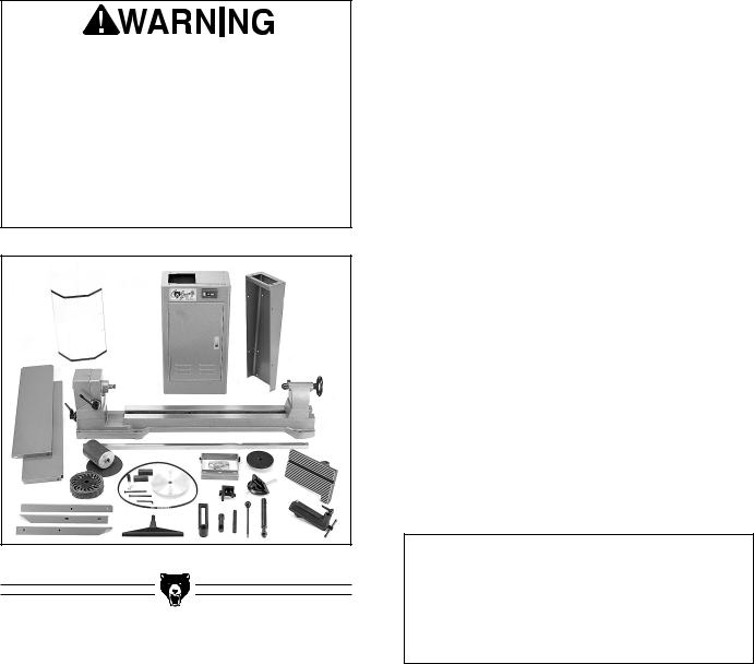
Figure 3. Parts Inventory.
G1495 Heavy-Duty Wood Lathe
Parts should be as follows (See Figure 3):
•Stand Assembly w/ Motor Installed
•Lathe Assembly
•V-Belt
•Right Hand Stand
•Support Shelves (2)
•Floor Brackets (3)
•Shield
•Shield Support Tube
•Shield Sliding Support
•Shield Hardware Bag
Mounting Bars |
2 |
Hex Bolts 5⁄16" - 18 x 41⁄2" |
2 |
Flat Washers 5⁄16" |
4 |
• Tailstock Handle |
|
• Sanding Attachments |
|
Flap Sander |
1 |
Pneumatic Drum |
1 |
Aluminum Sanding Disc |
1 |
Garnet Sanding Disc |
1 |
•Arbor for Mounting Sanding Acc
•Tilting Work Table
•Work Table Support Spindle
•Outboard Tool Rest Bracket w/ 3 Bolts
•Outboard Tool Rest Support
•Outboard Tool Rest Post w/ Nut
•Faceplate
•Miter Gauge
•Tool Rest Holder
•Tool Rest
•Knockout Bar
•Allen® Wrench 6mm
•Hardware Bag
Hex Bolts 5⁄16" - 18 x 3⁄4" |
18 |
Flat Washers 5⁄16" |
36 |
Cap Screws 5⁄16" - 18 x 21⁄2" |
6 |
Hex Nuts 5⁄16" - 18 |
24 |
In the event that any generally used fasteners are missing, we can replace them, or, for the sake of expediency, replacements can be obtained at your local hardware store.
NOTICE
A full parts list and illustrations can be found at the back of this manual. Use this information to identify parts or to clarify assembly steps.
-9-
 Loading...