


DRUM SANDER
MODEL G1066/G1066Z/G1079
INSTRUCTION MANUAL
|
|
|
|
|
|
|
|
Model G1066 |
|
|
|
Model G1066Z |
|
|
|
|
|
|
|
|
|
|
|
|
|
|
|
COPYRIGHT © MAY, 2002 BY GRIZZLY INDUSTRIAL, INC.
WARNING: NO PORTION OF THIS MANUAL MAY BE REPRODUCED IN ANY SHAPE
OR FORM WITHOUT THE WRITTEN APPROVAL OF GRIZZLY INDUSTRIAL, INC.
THE INFORMATION IN THIS MANUAL REPRESENTS THE CONFIGURATION OF THE MACHINE AS IT IS CURRENTLY BEING SHIPPED. THE MACHINE CONFIGURATION CAN CHANGE AS PRODUCT IMPROVEMENTS ARE INCORPORATED. IF YOU OWN AN EARLIER VERSION OF THE MACHINE, THIS MANUAL MAY NOT EXACTLY DEPICT YOUR MACHINE . CONTACT CUSTOMER SERVICE IF YOU HAVE ANY QUESTIONS ABOUT DIFFERENCES. PREVIOUS VERSIONS ARE NOT AVAILABLE ONLINE.
PRINTED IN TAIWAN

WARNING
Some dust created by power sanding, sawing, grinding, drilling, and other construction activities contains chemicals known to the State of California to cause cancer, birth defects or other reproductive harm. Some examples of these chemicals are:
•Lead from lead-based paints.
•Crystalline silica from bricks, cement, and other masonry products.
•Arsenic and chromium from chemically treated lumber.
Your risk from these exposures varies, depending on how often you do this type of work. To reduce your exposure to these chemicals: work in a well ventilated area, and work with approved safety equipment, such as those dust masks that are specially designed to filter out microscopic particles.
|
Table Of Contents |
|
|
|
PAGE |
1. |
SAFETY |
|
|
SAFETY RULES FOR POWER TOOLS ............................................................................ |
2-3 |
|
SAFETY RULES FOR THE DRUM SANDER ...................................................................... |
4 |
2. |
CIRCUIT REQUIREMENTS |
|
|
220V OPERATION ................................................................................................................ |
5 |
|
FUSING.................................................................................................................................. |
5 |
|
GROUNDING ........................................................................................................................ |
5 |
|
EXTENSION CORDS ............................................................................................................ |
6 |
|
WIRING DIAGRAMS ............................................................................................................ |
6 |
3. |
GENERAL INFORMATION |
|
|
COMMENTARY .................................................................................................................... |
7 |
|
UNPACKING.......................................................................................................................... |
8 |
|
PIECE INVENTORY .............................................................................................................. |
8 |
|
HARDWARE RECOGNITION CHART .................................................................................. |
9 |
|
CLEAN UP .......................................................................................................................... |
10 |
|
SITE CONSIDERATIONS.................................................................................................... |
10 |
4. |
ASSEMBLY |
|
|
BEGINNING ASSEMBLY .................................................................................................... |
11 |
|
DUST PORTS...................................................................................................................... |
11 |
|
CRANK HANDLE ................................................................................................................ |
12 |
|
G1066Z CONTROL PANEL ................................................................................................ |
12 |
5. |
ADJUSTMENTS |
|
|
DRUM ALIGNMENT ...................................................................................................... |
13-15 |
|
PRESSURE ROLLERS ...................................................................................................... |
16 |
|
DUST SCOOP .................................................................................................................... |
17 |
|
V-BELT ALIGNMENT .......................................................................................................... |
17 |
|
PAPER REPLACEMENT G1066/G1079 ........................................................................ |
18-19 |
|
PAPER REPLACEMENT G1066Z ...................................................................................... |
19 |
|
DUST COLLECTION .......................................................................................................... |
20 |
|
CONVEYOR BELT .............................................................................................................. |
21 |
6. |
OPERATIONS |
|
|
G1066Z CONTROL PANEL ................................................................................................ |
22 |
|
TEST RUN .......................................................................................................................... |
23 |
|
G1066/G1079 ...................................................................................................................... |
23 |
|
G1066Z .......................................................................................................................... |
24-25 |
|
CHOOSING SANDPAPER .................................................................................................. |
25 |
7.MAINTENANCE
|
GENERAL ............................................................................................................................ |
26 |
|
LUBRICATION .................................................................................................................... |
26 |
|
BEARING REPLACEMENT ................................................................................................ |
27 |
8. |
CLOSURE .................................................................................................................................. |
28 |
G1066 DATA SHEET ............................................................................................................................ |
29 |
|
G1066 PARTS BREAKDOWN ........................................................................................................ |
30-32 |
|
G1066 PARTS LIST .............................................................................................................................. |
33 |
|
G1066 WIRING DIAGRAM .................................................................................................................... |
34 |
|
G1066Z DATA SHEET .......................................................................................................................... |
35 |
|
G1066Z PARTS BREAKDOWN ...................................................................................................... |
36-38 |
|
G1066Z PARTS LIST ...................................................................................................................... |
39-40 |
|
G1066Z WIRING DIAGRAM.................................................................................................................. |
41 |
|
G1079 DATA SHEET ............................................................................................................................ |
42 |
|
G1079 PARTS BREAKDOWN ........................................................................................................ |
43-45 |
|
G1079 PARTS LIST .............................................................................................................................. |
46 |
|
G1079 WIRING DIAGRAM .................................................................................................................... |
47 |
|
TROUBLESHOOTING .......................................................................................................................... |
48 |
|
MAINTENANCE NOTES ...................................................................................................................... |
49 |
|
WARRANTY AND RETURNS .............................................................................................................. |
50 |
|
SECTION 1: SAFETY
For Your Own Safety Read Instruction Manual Before Operating This Equipment
The purpose of safety symbols is to attract your attention to possible hazardous conditions. This manual uses a series of symbols and signal words which are intended to convey the level of importance of the safety messages. The progression of symbols is described below. Remember that safety messages by themselves do not eliminate danger and are not a substitute for proper accident prevention measures.
Indicates an imminently hazardous situation which, if not avoided,
WILL result in death or serious injury.
Indicates a potentially hazardous situation which, if not avoided,
COULD result in death or serious injury.
Indicates a potentially hazardous situation which, if not avoided, MAY result in minor or moderate injury. It may also be used to alert against unsafe practices.
This symbol is used to alert the user to useful information about NOTICE proper operation of the equipment.
Safety Instructions For Power Tools
1.KEEP GUARDS IN PLACE and in working order.
2.REMOVE ADJUSTING KEYS AND WRENCHES. Form habit of checking to see that keys and adjusting wrenches are removed from tool before turning on.
3.KEEP WORK AREA CLEAN. Cluttered areas and benches invite accidents.
4.NEVER USE IN DANGEROUS ENVIRONMENT. Do not use power tools in damp or wet locations, or where any flammable or noxious fumes may exist. Keep work area well lighted.
-2-
5.KEEP CHILDREN AND VISITORS AWAY. All children and visitors should be kept at a safe distance from work area.
6.MAKE WORKSHOP CHILD PROOF with padlocks, master switches, or by removing starter keys.
7.NEVER FORCE TOOL. It will do the job better and safer at the rate for which it was designed.
8.USE RIGHT TOOL. Do not force tool or attachment to do a job for which it was not designed.
G1066/G1066Z/G1079 Drum Sander

Safety Instructions For Power Tools
9.USE PROPER EXTENSION CORD. Make sure your extension cord is in good condition. Conductor size should be in accordance with the chart below. The amperage rating should be listed on the motor or tool nameplate. An undersized cord will cause a drop in line voltage resulting in loss of power and overheating. Your extension cord must also contain a ground wire and plug pin. Always repair or replace extension cords if they become damaged.
Minimum Gauge for Extension Cords
|
|
LENGTH |
|
|
|
|
|
|
|
AMP RATING |
25ft |
|
50ft |
100ft |
|
|
|
|
|
0-6 |
18 |
|
16 |
16 |
|
|
|
|
|
7-10 |
18 |
|
16 |
14 |
|
|
|
|
|
11-12 |
16 |
|
16 |
14 |
|
|
|
|
|
13-16 |
14 |
|
12 |
12 |
|
|
|
|
|
17-20 |
12 |
|
12 |
10 |
21-30 |
10 |
|
10 |
No |
|
|
|
|
|
10.WEAR PROPER APPAREL. Do not wear loose clothing, gloves, neckties, rings, bracelets, or other jewelry which may get caught in moving parts. Non-slip footwear is recommended. Wear protective hair covering to contain long hair.
11.ALWAYS USE SAFETY GLASSES. Also use face or dust mask if cutting operation is dusty. Everyday eyeglasses only have impact resistant lenses, they are NOT safety glasses.
12.SECURE WORK. Use clamps or a vise to hold work when practical. It’s safer than using your hand and frees both hands to operate tool.
13.NEVER OVERREACH. Keep proper footing and balance at all times.
14.MAINTAIN TOOLS WITH CARE. Keep tools sharp and clean for best and safest performance. Follow instructions for lubricating and changing accessories.
15.DISCONNECT TOOLS before servicing and changing accessories, such as blades, bits, cutters, and the like.
16.REDUCE THE RISK OF UNINTENTIONAL STARTING. Make sure switch is in off position before plugging in. Also, the magnetic switch on this machine may start if the switch gets bumped hard enough.
17.USE RECOMMENDED ACCESSORIES.
Consult the owner’s manual for recommended accessories. The use of improper accessories may cause risk of injury.
18.CHECK DAMAGED PARTS. Before further use of the tool, a guard or other part that is damaged should be carefully checked to determine that it will operate properly and perform its intended function. Check for alignment of moving parts, binding of moving parts, breakage of parts, mounting, and any other conditions that may affect its operation. A guard or other part that is damaged should be properly repaired or replaced.
19.NEVER LEAVE TOOL RUNNING UNATTENDED. TURN POWER OFF. Do not leave tool until it comes to a complete stop.
20.NEVER USE UNDER THE INFLUENCE of alcohol or drugs, or when tired.
21. NEVER ALLOW UNSUPERVISED OR
UNTRAINED PERSONNEL TO OPERATE THE MACHINE. Make sure any instructions you give in regards to the operation of the machine are approved, correct, safe, and clearly understood.
G1066/G1066Z/G1079 Drum Sander |
-3- |

Additional Safety Instructions
For The Drum Sander
•DO NOT allow anyone to stand at the outfeed end when feeding your stock.
•DO NOT jam workpiece into the machine during operation. Firmly grasp the workpiece in both hands and ease it into the machine using light pressure.
•DO NOT wear loose clothing while operating this machine. Roll up or button sleeves at the cuff.
•DO NOT sand any stock narrower than
1⁄8''.
•DO NOT attempt to sand thin stock by using a “dummy” board under your workpiece.
•DO NOT sand stock shorter than 9''.
•DO NOT place hands near, or in contact with, sanding drums during operation.
•DO NOT allow fingers to get pinched between board and conveyor belt during operation. This may pull the operator’s hand into the machine and cause serious injury or death!
•NEVER leave the machine running unattended.
•NEVER operate the sander without an adequate dust collection system in place and running.
•NEVER sand more than one piece of stock at a time.
•ANY PROBLEM, with the exception of conveyor belt tracking, that is concerned at all with any moving parts or accessories must be investigated and corrected with the power disconnected, and after all moving parts have come to a complete stop. Never attempt to adjust conveyor belt tracking when the sanding drums are engaged.
•REPLACE sanding paper when it becomes worn.
•ALWAYS inspect board stock for nails, staples, knots, and other imperfections that could be dislodged and thrown from the machine during sanding operations.
•PERFORM machine inspections and maintenance service promptly when called for.
As with all power tools, there is danger associated with the G1066/G1066Z/G1079 Drum Sanders. Accidents are frequently caused by lack of familiarity or failure to pay attention. Use this tool with respect and caution to lessen the possibility of operator injury. If normal safety precautions are overlooked or ignored serious personal injury may occur.
Operating this equipment has the potential for creating flying debris which can cause eye injury. Always wear safety glasses or goggles when operating equipment. Everyday glasses or reading glasses only have impact resistant lenses, they are not safety glasses. Be certain the safety glasses you wear meet the appropriate standards of the American National Standards Institute (ANSI).
-4- |
G1066/G1066Z/G1079 Drum Sander |
SECTION 2: CIRCUIT REQUIREMENTS
220V Single-Phase |
|
Grounding |
|
|
|
|
|
|
The Model G1066/G1066Z/G1079 features 220V single-phase motors. The G1066/G1066Z 5 HP motor will safely draw about 25 amps under load. The G1079 2 HP drum motor requires 12 amps for safe operation. All sanders feature 1/4 HP feed motors that draw approx. 3 amps under load.
The Model G1066/G1066Z should be fused at 30 amps. The Model G1079 should be fused at 15 amps. Make sure the wiring in your circuit is rated to handle the amperage draw from your machine. If frequent circuit failure occurs when using the sander, contact our Service Department. The sander must be connected to its own dedicated circuit and should not share a circuit with any other machine. A standard 2-pole breaker is necessary for use with the sander.
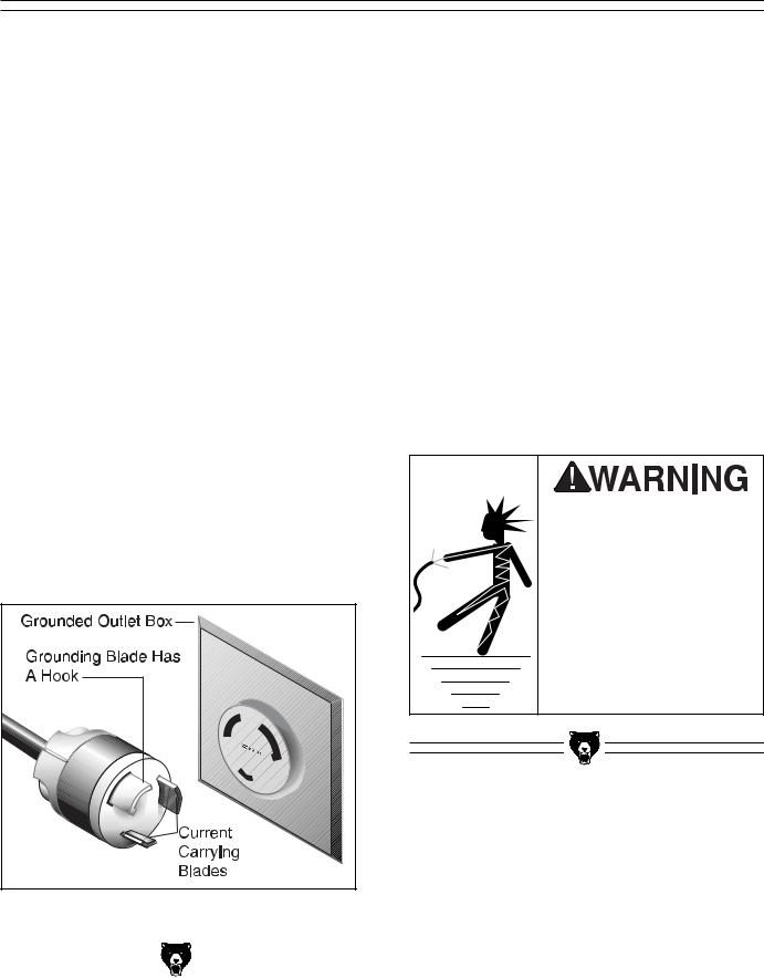
We recommend using a NEMA-style L6-30 plug and outlet for the Model G1066/G1066Z, and an L6-15 for the Model G1079. You may also “hardwire” the sander directly to your panel, provided you place a disconnect near the machine. Check the electrical codes in your area for specifics on wiring requirements.
Figure 1. Typical plug configuration for 220V, single-phase operation.
In the event of an electrical short, grounding reduces the risk of electric shock by providing a path of least resistance to disperse electric current. This tool is equipped with an electric cord that has an equipment-grounding conductor which must be properly connected to a grounding plug. The plug must be plugged into a matching outlet that is properly installed and grounded in accordance with all local codes and ordinances.
Improper connections of the electrical-grounding conductor can result in the risk of electric shock. The conductor with green or green and yellow striped insulation is the electrical-grounding conductor. If repair or replacement of the electric cord or plug is necessary, do not connect the equipment grounding conductor to a live terminal.
This equipment must be grounded. Verify that any existing electrical outlet and circuit you intend to plug into is actually grounded. Under no circumstances should the grounding pin from any three-pronged plug be removed. Serious injury may occur.
|
|
|
|
|
|
|
|
|
|
|
|
G1066/G1066Z/G1079 Drum Sander |
-5- |
||

Extension Cords |
Wiring Diagram |
|
|
|
|
|
|
|
We do not recommend the use of extension cords on 220V equipment. It is much better to arrange the placement of your equipment and the installed wiring to eliminate the need for extension cords. Should it be necessary to use an extension make sure the cord is rated Hard Service (grade S) or better. Refer to the chart in Section 1: Safety to determine the minimum gauge for the extension cord. The extension cord must also contain a ground wire and plug pin. Always repair or replace extension cords when they become worn or damaged.
The Model G1066/G1066Z/G1079 comes prewired for 220 volt operation. Wiring diagrams are provided at the back of this manual should it be necessary to repair or revise the wiring. Always consult a qualified electrician when doing any electrical work on this equipment.
We have covered some basic electrical requirements for the safe operation of your Sander. These requirements are not necessarily comprehensive. You must be sure that your particular electrical configuration complies with local and state codes. Ensure compliance by checking with your local municipality or a licensed electrician.
-6- |
G1066/G1066Z/G1079 Drum Sander |
SECTION 3: GENERAL INFORMATION
Commentary
We are proud to offer the Grizzly Model G1066/G1066Z/G1079 Drum Sander. Your machine is part of a growing Grizzly family of fine woodworking machinery. When used according to the guidelines set forth in this manual, you can expect years of trouble-free, enjoyable operation and proof of Grizzly’s commitment to customer satisfaction.
This manual covers all three models because these machines are essentially the same except for the motor size, the size of stock they can handle, the rotation of the drums and the feed rates. A number of optional accessories for these machines are available through the Grizzly catalog. Theses options include a complete selection of sanding paper, dust collection systems and a heavy-duty mobile base.
We are also pleased to provide this manual with the Model G1066/G1066Z/G1079. It was written to guide you through assembly, review safety considerations, and cover general operating procedures. It represents our effort to produce the best documentation possible. If you have any comments regarding this manual, please write to us at the address below:
Grizzly Industrial, Inc.
C/O Technical Documentation
P.O. Box 2069
Bellingham, WA 98227-2069
Most important, we stand behind our machines. If you have any service questions or parts requests, please call or write us at the location listed below.
Grizzly Industrial, Inc.
1203 Lycoming Mall Circle
Muncy, PA 17756
Phone: (570) 546-9663
Fax: (800) 438-5901 E-Mail: techsupport@grizzly.com Web Site: http://www.grizzly.com
The specifications, drawings, and photographs illustrated in this manual represent the Model G1066/G1066Z/G1079 as supplied when the manual was prepared. However, owing to Grizzly’s policy of continuous improvement, changes may be made at any time with no obligation on the part of Grizzly. Whenever possible, though, we send manual updates to all owners of a particular tool or machine. Should you receive one, we urge you to insert the new information with the old and keep it for reference.
Read the manual before assembly and operation. Become familiar with the machine and its operation before beginning any work. Serious personal injury may result if safety or operational information is not understood or followed.
|
|
|
|
|
|
|
|
|
|
|
|
|
Description |
|
|
G1066 |
|
|
G1066Z |
|
|
G1079 |
|
|
Motor Size |
|
|
5 HP |
|
|
5 HP |
|
|
2 HP |
|
|
Sanding Width |
|
|
231⁄2" |
|
|
231⁄2" |
|
|
16" |
|
|
Drum Rotation |
|
|
With Feed |
|
|
Against Feed |
|
|
With Feed |
|
|
|
|
|
|
|
|
|
|
|
|
|
|
Feed Rates |
|
|
11 FPM |
|
|
Var. 0-20 FPM |
|
|
11 FPM |
|
|
|
|
|
|
|
|
|
|
|
|
|
G1066/G1066Z/G1079 Drum Sander |
-7- |

Unpacking |
|
Piece Inventory |
|
|
|
|
|
|
The Model G1066/G1066Z/G1079 Drum Sander is shipped from the manufacturer in a carefully packed carton. If you discover your machine is damaged after you have signed for delivery, and the truck and driver are gone, you will need to file a freight claim with the carrier. Save the containers and all packing materials for possible inspection by the carrier or its agent. Without the packing materials, filing a freight claim can be difficult.
If you need assistance determining whether you need to file a freight claim, or with the procedure to file one, please contact our Customer Service.
The Model G1066/G1066Z/G1079 is a heavy machine (approx. 430 and 285 lb. shipping weights respectively). DO NOT over-exert yourself while unpacking or moving your machine—get assistance. In the event that your Drum Sander must be moved up or down a flight of stairs, be sure that the stairs are capable of supporting the combined weight of people and the machine. Serious personal injury may occur if they are not.
When you are completely satisfied with the condition of your shipment, you should inventory its parts.
After all the parts have been removed from the carton, you should have:
•Drum Sander Unit
•Control Panel [G1066Z]
•4'' Dust Port (2)
•Crank Arm
•Crank Handle
•Paper Retaining Clip (2) [G1066/G1079]
•Self Tapping Screws #8 x 1⁄2" (8)
•Flat Washers #8 (8)
•3MM Hex Wrench
In the event that any non-proprietary parts are missing (e.g. a nut or a washer), we would be glad to replace them, or for the sake of expediency, replacements can be obtained at your local hardware store.
NOTICE
A full parts list and breakdown can be found toward the end of this manual. For easier assembly, or to identify missing parts, please refer to the detailed illustrations at the end of the manual.
|
|
|
|
|
|
|
|
-8- |
|
|
G1066/G1066Z/G1079 Drum Sander |
|
|

Hardware Recognition Chart
Use this chart to match up hardware pieces during the assembly process!
CIRCLE |
1⁄4'' |
|
|
|
#10 |
|
|
|
|
|
Thumb |
INSIDE |
|
|
Screw |
5⁄16'' |
|
|
|
PLACING |
3⁄8'' |
|
Cap |
|
|
||
|
|
|
|
BY |
|
|
Screw |
1⁄2'' |
|
|
|
DIAMETER |
|
|
|
|
7⁄16'' |
|
|
BOLT |
|
|
Setscrew |
|
|
|
|
MEASURE |
5⁄8'' |
|
|
|
|
||
|
|
|
Washer |
|
4mm |
|
|
|
6mm |
|
5mm |
|
|
|
10mm |
|
8mm |
|
15mm |
|
APART |
20mm |
|
|
|
||
|
|
30mm |
|
|
|
|
25mm |
10mm |
1MM |
35mm |
|
|
|
||
|
|
|
|
|
|
ARE |
40mm |
|
|
45mm |
|
|
|
|
|
12mm |
LINES |
50mm |
|
|
|
60mm |
|
|
|
|
55mm |
|
|
|
65mm |
16mm |
|
70mm |
|
|
|
|
75mm |
|
|
|
|
|
|
R |
D |
|
|
|
|
|
|
|
|
I |
|
||
|
|
|
|
|
E |
|
A |
|
|
|
|
|
|
S |
H |
|
|
M |
|
|
|
|
|
|
|
|
|
T |
|
|
|
|
A |
|
|
|
|
|
E |
|
Lock |
Wing |
|
|
5⁄8'' |
|
E |
||
|
W |
|
|
||||||
|
Nut |
Nut |
|
|
|
|
|
|
R |
|
|
|
|
|
|
|
|
||
Phillips |
Countersunk |
|
|
|
|
|
|
|
|
Phillips |
Slotted |
|
|
|
|
|
|
|
|
Head |
Head |
|
|
|
R DI |
|
|||
|
|
|
|
|
|||||
|
|
Screw |
|
|
|
E |
|
A |
|
Screw |
Screw |
|
|
|
|
|
M |
||
|
|
|
S |
H |
|
|
E |
||
|
|
|
|
|
|
|
|
T |
|
|
|
|
|
A |
|
9⁄16'' |
|||
|
|
|
|
|
E |
||||
|
|
|
|
W |
|
|
R |
||
|
|
|
|
|
|
|
|
|
|
Carriage |
Flange |
||
Bolt |
|||
Bolt |
|||
|
|||
Hex |
Phillips |
||
Head |
|
||
Head |
|
||
Hex |
|
||
Bolt |
|
||
Bolt |
|
||
|
DIAMETER |
||
Washer |
Nut |
||
Lock |
Hex |
|
|
|
|
INSIDE |
|
1⁄4'' |
7⁄16'' |
THE |
|
1⁄2'' |
|||
3⁄8'' |
5⁄16'' |
|
|
5⁄8'' |
9⁄16'' |
BY |
|
|
3⁄4'' |
||
''⁄APARTINCH161 |
7⁄8'' |
MEASUREDARE |
|
1'' |
|||
|
|
||
|
11⁄4'' |
|
|
|
11⁄2'' |
|
|
|
13⁄4'' |
|
|
|
2 |
|
|
LINESARE |
21⁄4'' |
WASHERS |
|
3 |
|||
|
21⁄2'' |
|
|
|
23⁄4'' |
|
|
|
|
|
|
|
|
|
|
|
|
Button |
|
|
|
|
|
|
|
|
|
|
|
|
|
|
|
|
|
|
|
||||
|
|
|
|
|
|
|
|
|
|
Head |
|
|
|
|
|
|
|
|
D |
|
|
|
|
|
|
|
|
||||||
|
|
|
|
|
|
|
|
|
|
Screw |
|
|
|
|
R |
|
|
|
|
|
|
|
|
|
|||||||||
|
|
|
|
|
|
|
|
|
|
|
|
|
|
|
|
|
|
I |
|
|
|
|
|
|
|||||||||
|
|
|
|
|
|
|
|
|
|
|
|
|
|
|
|
|
E |
|
|
|
|
|
|
|
A |
E |
|
||||||
|
|
|
|
|
|
|
|
|
|
|
|
|
|
|
|
|
H |
|
|
|
|
|
|
|
|
|
|
|
|
||||
|
|
|
|
|
|
|
|
|
|
|
|
|
|
|
|
S |
|
|
|
|
|
|
|
|
|
|
|
M |
|
|
|
|
|
|
|
|
|
|
|
|
|
|
|
|
|
|
|
|
|
|
|
|
|
|
|
|
|
|
|
|
|
|
|
|
|
|
|
|
|
|
|
|
|
|
|
|
Phillips |
|
A |
|
|
|
1⁄2'' |
|
|
|
T |
||||||||||||||
|
|
|
|
|
|
|
|
|
W |
|
|
|
|
|
E |
||||||||||||||||||
|
|
|
|
|
|
|
|
|
Head |
|
|
|
|
|
|
|
|
|
|
|
|
|
|
|
R |
|
|
|
|||||
|
|
|
|
|
|
|
|
|
|
|
|
|
|
|
|
|
|
|
|
|
|
|
|
|
|
|
|
|
|||||
|
|
|
|
|
|
|
|
|
Sheet |
|
|
|
|
|
|
|
|
|
|
|
|
|
|
|
|
|
|
|
|
||||
|
|
|
|
|
|
|
|
|
Metal |
|
|
|
|
|
|
|
|
|
|
|
|
|
|
|
|
|
|
|
|
||||
|
|
|
|
|
|
|
|
|
Screw |
|
|
|
|
|
|
R |
|
D |
|
|
|
|
|
|
|||||||||
|
|
|
|
|
|
|
|
|
|
|
|
|
|
|
|
|
|
|
|
|
|
|
|
|
|
|
|||||||
|
|
|
|
|
|
|
|
|
|
|
|
|
|
|
|
|
|
|
|
|
|
|
|
I |
|
|
|
|
|
||||
|
|
|
|
|
|
|
|
|
|
|
|
|
|
|
|
|
H |
E |
|
|
|
|
|
|
|
A |
|
|
|
|
|||
|
|
|
|
|
|
|
|
|
|
|
|
|
|
|
|
|
|
|
|
|
|
|
|
|
|
|
|
E |
|||||
|
|
|
|
|
|
|
|
|
|
|
|
|
|
|
|
|
S |
|
|
|
|
|
|
|
|
|
|
M |
|
|
|||
|
|
|
|
|
|
|
|
|
|
|
|
|
|
|
|
|
|
|
7⁄16'' |
|
T |
||||||||||||
|
|
|
|
|
|
|
D |
|
|
|
|
|
|
|
|
A |
|
|
|||||||||||||||
|
|
|
|
|
R |
|
I |
|
|
|
|
|
|
|
W |
|
|
|
|
|
|
|
|
|
E |
|
|
||||||
|
|
|
|
|
|
|
A |
E |
|
|
|
|
|
|
|
|
|
|
|
|
R |
|
|
||||||||||
|
|
|
|
E |
|
|
|
|
|
|
|
|
|
|
|
|
|
|
|
|
|
|
|
|
|
|
|
|
|
||||
|
S |
H |
|
|
|
|
|
|
M |
|
|
|
|
|
|
|
|
|
|
|
|
|
|
|
|
|
|
|
|
|
|
||
|
|
|
|
|
|
|
|
T |
|
|
|
|
|
|
|
|
|
|
|
|
|
|
|
|
|
|
|
|
|
||||
|
A |
|
|
|
12mm |
|
|
|
|
|
|
|
|
|
|
|
|
|
|
|
|
|
|
|
|
|
|||||||
|
|
|
|
E |
|
|
|
|
|
|
|
|
|
|
|
|
|
|
|
|
|
|
|
|
|||||||||
|
W |
|
|
|
|
|
|
R |
|
|
|
|
|
|
|
|
|
|
|
|
|
|
|
|
|
|
|
|
|
||||
|
|
|
|
|
|
|
|
|
|
|
|
|
|
|
|
|
|
|
|
|
|
|
|
|
|
|
|
|
|
||||
|
|
|
|
|
|
|
|
|
|
|
|
|
|
|
|
|
|
|
|
R |
|
D |
|
|
|
|
|
||||||
|
|
|
|
|
|
|
|
|
|
|
|
|
|
|
|
|
|
|
|
|
|
I |
|
|
|
|
|||||||
|
|
|
|
|
|
|
|
|
|
|
|
|
|
|
|
|
|
|
H |
E |
|
|
|
|
|
|
A |
|
|
|
|||
|
|
|
|
|
|
|
|
|
|
|
|
|
|
|
|
|
|
|
|
|
|
|
|
|
|
M |
|||||||
|
|
|
|
|
|
|
|
|
|
|
|
|
|
|
|
|
S |
|
|
|
3 |
⁄8'' |
|
E |
|||||||||
|
|
|
|
|
|
|
|
|
|
|
|
|
R DI |
|
|
A |
|
|
|
|
|
E |
T |
||||||||||
|
|
|
|
|
|
|
|
|
|
|
|
|
|
|
|
|
W |
|
|
|
|
|
|
|
|||||||||
|
|
|
|
|
|
|
|
|
|
|
|
|
|
|
|
|
|
|
|
|
|
|
|
|
|
|
|||||||
|
|
|
|
|
|
|
|
|
|
|
|
H |
E |
A |
|
|
|
|
|
|
|
|
|
R |
|
|
|
||||||
|
|
|
|
|
|
|
|
|
|
|
|
|
M |
|
|
|
|
|
|
|
|
|
|
|
|
|
|
|
|||||
|
|
|
|
|
|
|
|
|
|
|
|
S |
E |
|
|
|
|
|
|
|
|
|
|
|
|
|
|
|
|
|
|
||
|
|
|
|
|
|
|
|
|
|
|
|
A |
|
T |
|
|
|
|
|
|
|
|
|
|
|
|
|
|
|
|
|
|
|
|
|
|
|
|
|
|
|
|
|
|
|
|
W |
E |
|
|
|
|
|
|
|
|
|
|
|
|
|
|
|
|
|
|
|
|
|
|
|
|
|
D |
|
|
|
|
|
R |
|
|
|
|
|
|
|
|
|
|
|
|
|
|
|
|
|
|
|
||
|
|
|
|
R |
|
|
|
|
|
|
|
|
|
|
|
|
|
|
|
|
|
|
|
|
|
|
|
|
|
|
|||
|
|
|
|
|
I |
|
|
|
|
4mm |
|
|
|
|
|
|
|
|
|
|
|
|
|
D |
|
|
|
|
|||||
|
E |
|
|
|
AM |
|
|
|
|
|
|
|
|
|
R |
|
|
|
|
||||||||||||||
|
H |
|
|
|
|
|
|
|
|
|
|
|
|
|
|
|
|
|
|
|
|
I |
|
|
|
|
|||||||
S |
|
|
|
|
|
|
|
|
|
|
|
|
|
|
|
|
|
|
H |
E |
|
|
|
|
|
A |
|
|
|||||
|
|
|
|
|
|
|
|
|
T |
|
|
|
|
|
|
|
|
|
5 |
|
|
M |
|||||||||||
A |
|
|
|
|
|
|
|
|
|
E |
|
|
|
|
|
|
|
|
|
|
|
|
|
|
|
⁄16'' |
|
E |
|||||
|
|
10mm |
|
|
E |
|
|
|
|
|
|
|
|
S |
|
|
|
|
|
|
|||||||||||||
W |
|
|
|
|
|
|
|
|
|
|
|
A |
|
|
|
|
|
|
|
|
T |
|
|||||||||||
|
|
|
|
|
|
|
|
|
|
|
R |
|
|
|
|
|
|
|
|
|
|
W |
|
|
E |
|
|
||||||
|
|
|
|
|
|
|
|
|
|
|
|
|
|
|
|
|
|
|
|
|
|
|
R |
|
|
|
|
||||||
|
|
|
|
|
|
|
|
|
|
|
|
|
|
D |
|
|
|
|
|
|
|
|
|
|
|
|
|
D |
|
|
|
|
|
|
|
|
|
|
|
|
|
|
|
|
|
|
|
|
|
|
|
|
|
|
|
|
R |
A |
|
|
|||||||
|
|
|
|
|
|
|
|
|
|
|
|
R |
I |
|
|
|
|
|
|
|
|
|
I |
|
|
|
|
||||||
|
|
|
|
|
|
|
|
|
|
|
|
|
|
|
|
|
|
|
|
E |
|
|
|
|
|
|
|
|
|||||
|
|
|
|
|
|
|
|
|
|
|
H |
E |
|
A |
|
|
|
|
|
|
H |
|
|
|
M |
||||||||
|
|
|
|
|
|
|
|
|
|
|
|
M |
|
|
|
|
|
|
|
|
|
|
|||||||||||
|
|
|
|
|
|
|
|
|
|
|
|
|
|
|
|
|
|
|
A |
1 |
⁄4'' |
|
|
E |
|||||||||
|
|
|
|
|
|
|
|
|
|
|
S |
|
|
E |
|
|
S |
|
|
|
|
|
|
T |
|
||||||||
|
|
|
|
|
|
|
|
|
|
|
A |
|
|
T |
|
|
|
|
|
|
W |
|
E |
|
|||||||||
|
|
|
|
|
|
|
|
|
|
|
|
|
|
|
|
|
|
|
|
|
|
||||||||||||
|
|
|
|
|
|
|
|
|
|
|
E |
|
|
|
|
|
|
|
|
|
|
|
|
|
|
|
|
|
|
||||
|
|
|
|
|
|
|
|
|
|
|
|
W |
R |
|
|
|
|
|
|
|
|
|
|
|
|
|
|
|
|
|
|
|
|
|
R |
D |
|
|
|
|
|
|
|
|
|
|
|
|
|
|
|
|
|
|
|
|
|
|
|
|
|
|
|
||||
|
|
I |
|
|
|
|
|
|
|
|
|
|
|
|
|
|
|
|
|
|
|
|
|
|
|
|
|
|
|||||
H |
E |
|
|
|
|
A |
|
|
|
|
6mm |
|
|
|
|
|
|
|
|
|
|
|
|
|
R DI |
|
|
|
|||||
|
|
|
|
|
M |
|
|
|
|
|
|
|
|
|
|
|
|
|
|
|
|
|
|
||||||||||
|
|
|
|
|
|
|
|
|
|
|
|
|
|
|
|
|
|
|
|
|
|
|
|
|
|
E |
A |
||||||
S |
|
|
|
|
|
|
|
E |
|
|
|
|
|
|
|
|
|
|
|
|
|
S |
|
|
|||||||||
|
|
|
|
|
|
|
|
|
|
|
|
|
|
|
|
|
|
|
|
|
|
|
|
|
|
|
|||||||
A |
|
8mm |
|
|
|
|
|
|
|
|
|
|
|
|
|
|
|
H |
|
|
|
M |
|||||||||||
|
|
|
T |
|
|
|
|
|
|
|
|
|
|
|
|
|
A |
|
|
|
|
E |
|||||||||||
W |
|
|
|
|
|
|
|
E |
|
|
|
|
|
|
|
|
|
|
|
|
|
|
|
|
W |
|
E |
T |
|||||
|
|
|
|
|
R |
|
|
|
|
|
|
|
|
|
|
|
|
|
|
|
|
R |
|
|
|
||||||||
|
|
|
|
|
|
|
|
|
|
|
|
|
|
|
|
|
|
|
|
|
|
|
|
|
|
|
|
|
|
|
|
||
#10
G1066/G1066Z/G1079 Drum Sander |
-9- |
Clean Up
The unpainted surfaces are coated with a waxy oil to protect them from corrosion during shipment. Remove this protective coating with a solvent cleaner or citrus-based degreaser such as Grizzly’s G7895 Degreaser. To clean thoroughly, some parts may need to be removed. Avoid chlo- rine-based solvents as they may damage painted surfaces should they come in contact. Always follow the manufacturer’s instructions when using any type of cleaning product.
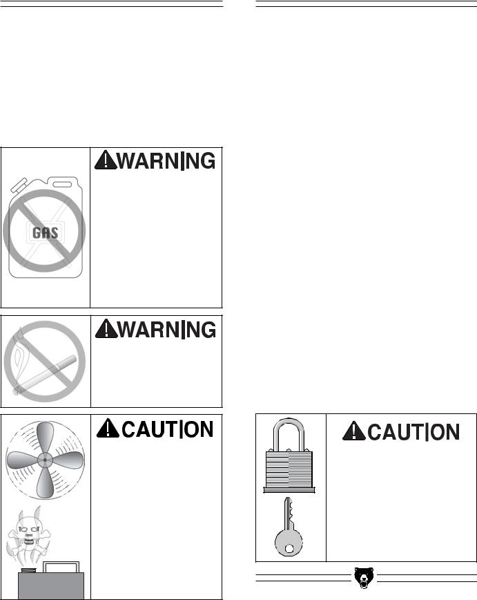
Do not use gasoline or other petroleum-based solvents to clean with. They have low flash points which make them extremely flammable. A risk of explosion and burning exists if these p r o d u c t s a r e u s e d . Serious personal injury may occur.
Do not smoke while using solvents. A risk of explosion or fire exists and may result in serious personal injury.
Many of the solvents commonly used to clean machinery can be toxic when inhaled or ingested. Always work in wellventilated areas far from potential ignition sources when dealing with solvents. Use care when disposing of waste rags and towels to be sure they do not create fire or environmental hazards.
-10-
Site Considerations
FLOOR LOAD
Your new drum sander represents a large weight load in a moderate sized footprint. Most shop floors will be adequate for the weight of the drum sander; however, some floors may require additional support. Contact an architect or structural engineer if you have any question about the ability of your floor to handle the weight.
WORKING CLEARANCES
Working clearances can be thought of as the distances between machines and obstacles that allow safe operation of every machine without limitation. Consider existing and anticipated machine needs, size of material to be processed through each machine, and space for auxiliary stands and/or work tables. Also consider the relative position of each machine to one another for efficient material handling. Be sure to allow yourself sufficient room to safely run your machines in any foreseeable operation.
LIGHTING AND OUTLETS
Lighting should be bright enough to eliminate shadow and prevent eye strain. Electrical circuits should be dedicated or large enough to handle combined motor amp loads. Outlets should be located near each machine so power or extension cords are not obstructing high-traffic areas. Be sure to observe local electrical codes for proper installation of new lighting, outlets or circuits.
Make your shop “child safe.” Ensure that your workplace is inaccessible to children by closing and locking all entrances when you are away. Never allow visitors in your shop when assembling, adjusting or operating equipment.
G1066/G1066Z/G1079 Drum Sander
SECTION 4: ASSEMBLY
Beginning Assembly |
Dust Ports |
|
|
|
|
|
|
|
Most of your new drum sander has been assembled at the factory, but some parts must be assembled or installed after delivery. We have organized the assembly process into steps. Please follow along in the order presented in this section.
Keep loose clothing out of the way of machinery and keep hair pulled back.
Disconnect power to the machine when performing any maintenance or assembly. Failure to do this may result in serious personal injury.
Wear safety glasses during the entire assembly process. Failure to comply may result in serious personal injury.
Some metal parts may have sharp edges on them after they are formed. Please examine the edges of all metal parts before handling them. Failure to do so could result in injury.
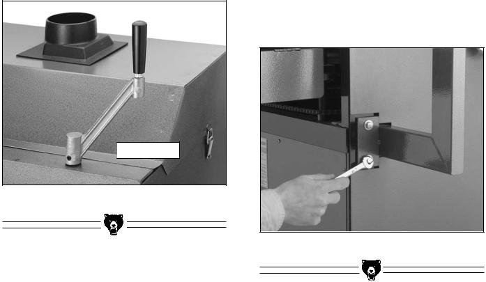
The Model G1066/G1079 Drum Sander comes equipped with two 4'' dust ports as shown in Figure 2. Apply double sided tape between the plastic dust ports and the sheet metal cover, then secure in place with sheet metal screws.
Figure 2. Top-mounted 4" dust ports.
The Model G1066Z also comes equipped with two 4" dust ports, but these mount in the center of the top and the center of the front on the sheet metal cover. As with the other models, apply double sided tape between the plastic dust ports and the sheet metal cover, then secure in place with sheet metal screws.
DO NOT operate the Model G1066/G1066Z/G1079 without an adequate dust collection system. This machine creates substantial amounts of wood dust while in operation. Failure to use a dust collection system can result in short and long-term respiratory illness.
|
|
|
|
G1066/G1066Z/G1079 Drum Sander |
-11- |
||
Crank Handle |
G1066Z Control Panel |
||
|
|
|
|
|
|
|
|
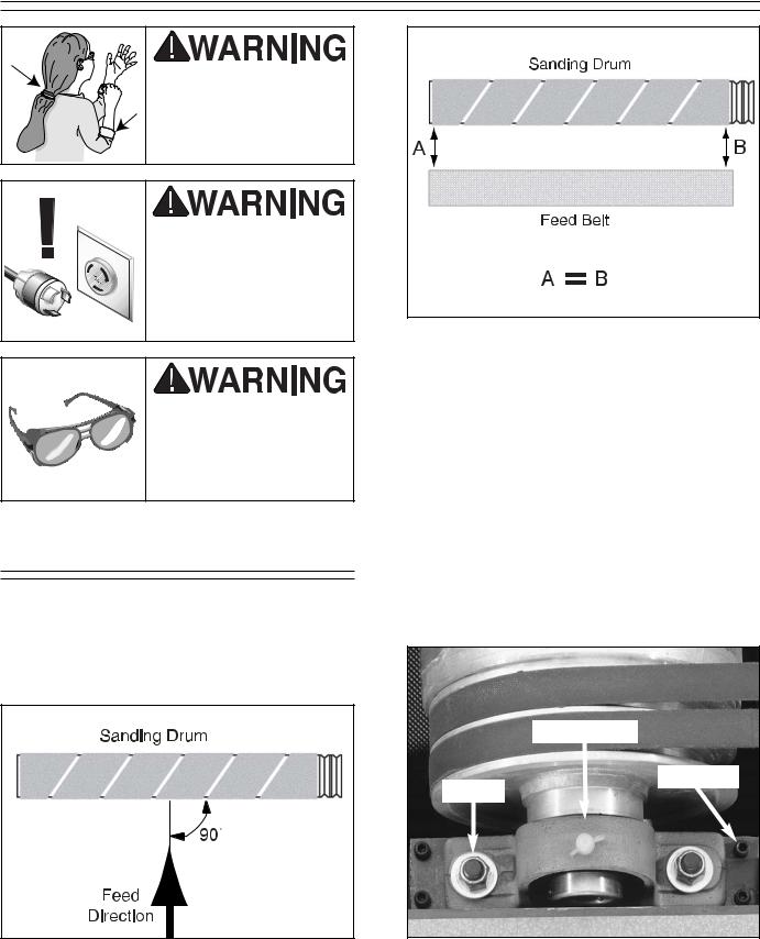
The crank handle is normally installed on the front right lead screw shaft, and is held in place with two setscrews already threaded into the handle, as shown in Figure 3. The crank handle can be installed on the right or left side of the machine to maximize operator comfort and convenience.

 Setscrew
Figure 3. Crank handle attachment.
To mount the control panel to the base unit on the Model G1066Z:
1.Match the holes in the control arm mounting plate to the threaded holes on the side of the the sander.
2.Use the 5⁄16"-18 x 1" hex bolts and washers to secure the control arm to the sander body as shown in Figure 4.
Figure 4. Control panel attached to base unit.
|
|
|
|
-12- |
G1066/G1066Z/G1079 Drum Sander |
||
SECTION 5: ADJUSTMENTS
Keep loose clothing out of the way of machinery and keep hair pulled back.
Disconnect power to the machine when performing any adjustments or maintenance. Failure to do this may result in serious personal injury.
Wear safety glasses during the entire adjustment process. Failure to comply may result in serious personal injury.
Drum Alignment
For the Model G1066/G1066Z/G1079 Drum Sander to function properly, the sanding drums must be aligned in two directions: (1) perpendicular to feed direction (Figures 5 and 6) and (2) parallel to the conveyor belt.
Figure 6. Sanding drum parallel to feed belt.
In order to make the above adjustments, it is necessary to know how to adjust the bearing blocks.
To adjust the Model G1066/G1066Z/G1079 bearing blocks:
1.Loosen the lock nuts (See Figure 7) on one of the bearing blocks on the drum that requires adjustment.
2.Raise or lower the bearing block by rotating the setscrews (See Figure 7). Turn very gradually 1⁄8 of a turn or less.
Bearing Block
Setscrews
Locknut
Figure 5. Feed direction perpendicular to drum. |
Figure 7. Bearing block adjustments. |
|
|
G1066/G1066Z/G1079 Drum Sander |
-13- |
3.Tighten the lock nuts and recheck the alignment using the same hardwood block. Tightening the lock nuts will pull the drum downward slightly. Be sure to adjust to compensate for this movement. Do not over tighten the lock nuts. The bearing blocks can break if over tightened.
4.For Models G1066/G1079 repeat steps 1-3 for the other drum. Tighten the lock nuts. Model G1066Z has micro-adjustment knobs on the sides of the machine for rear drum adjustments. See Figure 9. Both drums should now be properly adjusted. Do not change the table height until the lock nuts are tight.
Use care when tightening lock nuts. While they are made of durable cast metal, the bearing blocks are susceptible to breakage if the metal is fatigued by excess tension caused by overtightening.
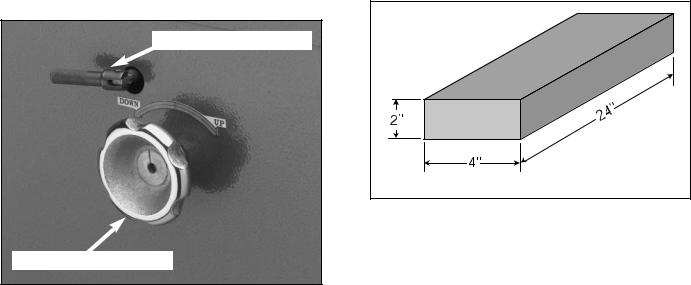
Micro-Adjust Lock Knob
Micro-Adjustment Knob
Figure 9. Model G1066Z rear drum adjustment control.
To adjust the drums perpendicular to the feed direction:
1.Disconnect the sander from the power source!
2.First measure the distance between the outside of the front drum and the inside of the front brace. The distances should be within 1⁄8" of each other at each end of the drum.
3.Repeat the measurements with the rear drum and brace. If the measurements are not within 1⁄8", the drums can be moved by loosening the lock nuts on the bearing blocks and moving one end of the drum forward or backward as necessary in the slotted holes.
If the drums are not perpendicular to feed direction, the sandpaper will creep toward one end of the drum. After you have adjusted the drums, do not forget to tighten the lock nuts and recheck the alignment.
To adjust the drums parallel to the conveyor belt:
1.Disconnect the sander from the power source!
2.For this step, you will need a 24" long block of wood. A quality 2x4 will work fine (See
Figure 10).
Figure 10. Dimensions of gauge block.
3.Start with the front sanding drum. Lower the table so the block will slide easily under the pressure bars. Slide the block over to one side of the table, with the front edge lined up to the front of the table. (It is important to line up the block carefully to ensure that the same part of the 2x4 is used to set the drum heights.) Raise the table up so the board barely touches the front pressure roller.
4.Raise the table one full turn of the handwheel. Adjust the height of that side of the front sanding drum so it just touches the board and is able to rock back and forth with moderate resistance.
-14- |
G1066/G1066Z/G1079 Drum Sander |

5.Stop and mark the location of the table elevation handle with a felt pen or piece of tape. In the same manner, mark the height of the table in relation to the body of the sander. Both of these marks will indicate this exact table position (we will refer to it as reference height #1). Having reference height #1 marked is crucial to all subsequent steps.
6.Lower the table exactly 2 turns. Remove the block and re-insert it on the other side, taking care to line it up with the front of the table just as it was on the previous side. Raise the table exactly 2 turns to bring it back up to reference height #1.
7.Set the height of that end of the drum to the board. Rock the drum back and forth again. It should feel and sound the same as it did on the other end. If the sound and rolling action are not identical, adjust the bearing block height. Continue this procedure, going back and forth, until both sides of the drum sound and feel the same.
8.To adjust the rear drum, lower the table by turning the handwheel counter-clockwise
1/8th of a turn from reference #1. Make a second mark. This will be reference #2 and will be used for setting up the rear drums.
9.Repeat steps 5-6 until both sides of the rear drum are the same. (Note: the G1066Z has external height adjustment knobs for the rear drum. These are located on each side of the machine. Other than this difference, the procedure for setting the drum height is the same.)
10.While the rear drum should always be slightly lower than the front drum, the actual difference will vary depending on wood type, feed rate, sandpaper grits, etc. Once you are familiar and comfortable with the adjustment procedures, you should experiment to arrive at the best settings for your specific application.
In addition to premature wear and failure of sandpaper, improper drum alignment could cause the possibility of an uncontrolled exit of material from the machine—which could result in damage to property or potential operator injury.
G1066/G1066Z/G1079 Drum Sander |
-15- |
 Loading...