


9 'X 19 'METAL LATHE
MODEL G4000
INSTRUCTION MANUAL
COPYRIGHT © 1999 BY GRIZZLY INDUSTRIAL, INC.
WARNING: NO PORTION OF THIS MANUAL MAY BE REPRODUCED IN ANY SHAPE OR FORM WITHOUT THE WRITTEN APPROVAL OF GRIZZLY INDUSTRIAL, INC.
REVISED OCTOBER, 1999 PRINTED IN U.S.A.

|
Table Of Contents |
|
|
|
PAGE |
1. |
SAFETY |
|
|
SAFETY RULES FOR POWER TOOLS .......................................................... |
2-3 |
|
ADDITIONAL SAFETY INSTRUCTIONS FOR METAL LATHES ........................ |
4 |
2. |
CIRCUIT REQUIREMENTS |
|
|
110V OPERATION .............................................................................................. |
5 |
|
EXTENSION CORDS .......................................................................................... |
5 |
|
GROUNDING ...................................................................................................... |
5 |
3. |
INTRODUCTION |
|
|
COMMENTARY.................................................................................................... |
6 |
|
UNPACKING ........................................................................................................ |
7 |
|
PIECE INVENTORY ............................................................................................ |
7 |
|
CLEAN UP............................................................................................................ |
8 |
|
SITE CONSIDERATIONS .................................................................................... |
8 |
4.ASSEMBLY & SETUP
|
MOUNTING .......................................................................................................... |
9 |
|
LUBRICATION .................................................................................................... |
9 |
|
CHUCKS ........................................................................................................ |
9-10 |
|
LIVE CENTER .................................................................................................... |
10 |
|
STEADY REST .................................................................................................. |
11 |
|
FOLLOW REST.................................................................................................. |
11 |
5. |
CONTROLS |
|
|
SPINDLE SPEEDS ............................................................................................ |
12 |
|
FEED RATE ...................................................................................................... |
13 |
|
CARRIAGE CONTROLS .............................................................................. |
14-16 |
|
TAILSTOCK CONTROLS .................................................................................. |
16 |
|
TEST RUN.......................................................................................................... |
17 |
6. |
ADJUSTMENTS |
|
|
SPINDLE RPM .................................................................................................. |
18 |
|
GIBS.............................................................................................................. |
18-19 |
|
STEADY REST/FOLLOW REST........................................................................ |
19 |
|
CHUCK RUNOUT ........................................................................................ |
20-21 |
|
TAILSTOCK .................................................................................................. |
21-22 |
|
THREAD CUTTING............................................................................................ |
23 |
7. |
MAINTENANCE |
|
|
LUBRICATION .............................................................................................. |
24-25 |
|
BEARING PRELOAD ........................................................................................ |
25 |
8. |
CLOSURE ................................................................................................................ |
26 |
MACHINE DATA ................................................................................................................ |
27 |
|
BELT CONFIGURATION CHART ...................................................................................... |
28 |
|
STOCK RPM CHART ........................................................................................................ |
29 |
|
PARTS BREAKDOWN AND PARTS LISTS ................................................................ |
30-53 |
|
WARRANTY AND RETURNS ............................................................................................ |
54 |
|
G4000 9'' x 19'' Lathe |
-1- |
SECTION 1: SAFETY
For Your Own Safety Read Instruction Manual Before Operating This Equipment
The purpose of safety symbols is to attract your attention to possible hazardous conditions. This manual uses a series of symbols and signal words which are intended to convey the level of importance of the safety messages. The progression of symbols is described below. Remember that safety messages by themselves do not eliminate danger and are not a substitute for proper accident prevention measures.
|
|
|
|
|
|
|
Indicates an imminently hazardous situation which, if not |
|
|
|
|
|
|
|
|
avoided, WILL result in death or serious injury. |
|
|
|
|
|
|
|
|
|
Indicates a potentially hazardous situation which, if not |
|
|
|
|
|
|
|
|
|
|
|
|
|
|
|
|
|
|
|
|
|
|
|
|
|
|
avoided, COULD result in death or serious injury. |
|
|
|
|
|
|
|
|
|
|
|
|
|
|
|
|
Indicates a potentially hazardous situation which, if not |
|
|
|
|
|
|
|
|||
|
|
|
|
|
|
|
avoided, MAY result in minor or moderate injury. It may also |
|
|
|
|
|
|
|
|
be used to alert against unsafe practices. |
|
|
|
|
|
|
|
|||
|
|
|
|
|
|
|
|
|
|
NOTICE |
|
|
This symbol is used to alert the user to useful information |
||||
|
|
|
about proper operation of the equipment. |
|||||
|
|
|
|
|
|
|
|
|
Safety Instructions For Power Tools
1.KEEP GUARDS IN PLACE and in working order.
2.REMOVE ADJUSTING KEYS AND WRENCHES. Develop a habit of checking to see that keys and adjusting wrenches are removed from tool before turning on.
3.KEEP WORK AREA CLEAN. Cluttered areas and benches invite accidents.
4.DON’T USE IN DANGEROUS ENVIRONMENT. Don’t use power tools in damp or wet locations, or where any flammable or noxious fumes may exist. Keep work area well lighted.
5.KEEP CHILDREN AND VISITORS AWAY. All children and visitors should be kept a safe distance from work area.
6.MAKE WORK SHOP CHILD PROOF with padlocks, master switches, or by removing starter keys.
7.DON’T FORCE TOOL. It will do the job better and safer at the rate for which it was designed.
8.USE RIGHT TOOL. Don’t force tool or attachment to do a job for which it was not designed.
-2- |
G4000 9'' x 19'' Lathe |

Safety Instructions For Power Tools
9.USE PROPER EXTENSION CORD. Make sure your extension cord is in good condition. Conductor size should be in accordance with the chart below. The amperage rating should be listed on the motor or tool nameplate. An undersized cord will cause a drop in line voltage resulting in loss of power and overheating. Your extension cord must also contain a ground wire and plug pin. Always repair or replace extension cords if they become damaged.
Minimum Gauge for Extension Cords
|
|
LENGTH |
|
||
AMP RATING |
25ft |
|
50ft |
|
100ft |
0-6 |
18 |
|
16 |
|
16 |
7-10 |
18 |
|
16 |
|
14 |
11-12 |
16 |
|
16 |
|
14 |
13-16 |
14 |
|
12 |
|
12 |
17-20 |
12 |
|
12 |
|
10 |
21-30 |
10 |
|
10 |
|
No |
|
|
|
|
|
|
10.WEAR PROPER APPAREL. Do not wear loose clothing, gloves, neckties, rings, bracelets, or other jewelry which may get caught in moving parts. Non-slip footwear is recommended. Wear protective hair covering to contain long hair.
11.ALWAYS USE SAFETY GLASSES. Also use face or dust mask if cutting operation is dusty. Everyday eyeglasses only have impact resistant lenses, they are NOT safety glasses.
12.SECURE WORK. Use clamps or a vise to hold work when practical. It’s safer than using your hand and frees both hands to operate tool.
13.DON’T OVERREACH. Keep proper footing and balance at all times.
14.MAINTAIN TOOLS WITH CARE. Keep tools sharp and clean for best and safest performance. Follow instructions for lubricating and changing accessories.
15.DISCONNECT TOOLS before servicing and changing accessories, such as blades, bits, cutters, and the like.
16.REDUCE THE RISK OF UNINTENTIONAL STARTING. Make sure switch is in off position before plugging in.
17.USE RECOMMENDED ACCESSORIES.
Consult the owner’s manual for recommended accessories. The use of improper accessories may cause risk of injury.
18.CHECK DAMAGED PARTS. Before further use of the tool, a guard or other part that is damaged should be carefully checked to determine that it will operate properly and perform its intended function. Check for alignment of moving parts, binding of moving parts, breakage of parts, mounting, and any other conditions that may affect its operation. A guard or other part that is damaged should be properly repaired or replaced.
19.NEVER LEAVE TOOL RUNNING UNATTENDED. TURN POWER OFF. Don’t leave tool until it comes to a complete stop.
G4000 9'' x 19'' Lathe |
-3- |
Additional Safety Instructions For The Lathe
1.MAKE SURE ALL GUARDS are in place and that the lathe sits on a flat, stable surface.
2.BEFORE STARTING THE MACHINE be certain the workpiece has been properly engaged in the chuck and tailstock center (if in use) and that there is adequate clearance for full rotation.
3.ADJUST TOOL HOLDER to provide proper support for the turning tool you will be using. Test tool holder clearance by rotating workpiece by hand before turning lathe on.
4.SELECT THE TURNING SPEED which is appropriate for the type of work and the type of material. Allow the lathe to gain its full speed before beginning turning.
5.NEVER CHANGE FEED RATE or spindle speeds while the lathe is turning.
6.NEVER REVERSE MOTOR DIRECTION while the lathe is running.
7.DO NOT STOP LATHE USING YOUR HAND against the workpiece.
8.DO NOT LEAVE LATHE RUNNING UNATTENDED for any reason.
9.NEVER OPERATE THE LATHE WITH DAMAGED OR WORN PARTS. Maintain your lathe in proper working condition. Perform routine inspections and maintenance promptly when called for. Put away adjustment tools after use.
10.MAKE SURE YOUR METAL LATHE IS TURNED OFF, disconnected from its power source and all moving parts have come to a complete stop before starting any inspection, adjustment, or maintenance procedure.
11.KEEP LOOSE CLOTHING ARTICLES such as sleeves, belts or jewelry items away from the lathe spindle.
12.ALWAYS USE THE PROPER CUTTING TOOLS for the material you are turning, make certain they are sharp and that they are held firmly in the tool holder.
13.ALWAYS PLACE A BOARD OR PIECE OF PLYWOOD ACROSS THE BEDWAY when removing or installing chucks to avoid the possibility of a finger pinch point occurring between a loose chuck and the edges of the bedway.
No list of safety guidelines can be complete. Every shop environment is different. Always consider safety first, as it applies to your individual working conditions. Use this and other machinery with caution and respect. Failure to do so could result in serious personal injury, damage to equipment or poor work results.
Like all power tools, there is danger associated with the Model G4000 Metal Lathe. Accidents are frequently caused by lack of familiarity or failure to pay attention. Use this tool with respect and caution to lessen the possibility of operator injury. If normal safety precautions are overlooked or ignored serious personal injury may occur.
-4- |
G4000 9'' x 19'' Lathe |

SECTION 2: CIRCUIT REQUIREMENTS
110V Operation |
Grounding |
The Model G4000 is wired for 110 volt, single phase operation only. The 3⁄4 HP motor will safely draw 12 amps at 110V. A 15-amp fuse or circuit breaker should be used when connecting this metal lathe. Circuits rated any higher are not adequate to protect the motor.
If you operate this lathe on any circuit that is already close to its capacity, it might blow a fuse or trip a circuit breaker. However, if an unusual load does not exist and a power failure still occurs, contact a qualified electrician or our service department.
Equipment returned to us for service that shows evidence of being over-fused will be repaired or replaced totally at the customer’s expense, regardless of the present warranty status.
Extension Cords
If you find it necessary to use an extension cord with the Model G4000, make sure the cord is rated Hard Service (grade S) or better. Refer to the chart in the standard safety instructions to determine the minimum gauge for the extension cord. The extension cord must also contain a ground wire and plug pin. Always repair or replace extension cords when they become worn or damaged.
In the event of an electrical short, grounding reduces the risk of electric shock by providing a path of least resistance to disperse electric current. This tool is equipped with a power cord having an equipment-grounding conductor. See Figure 1. The outlet must be properly installed and grounded in accordance with all local codes and ordinances.
This equipment must be grounded. Verify that any existing electrical outlet and circuit you intend to plug into is actually grounded. If it is not, it will be necessary to run a separate 12 A.W.G. copper grounding wire from the outlet to a known ground. Under no circumstances should the grounding pin from any three-pronged plug be removed. Serious injury may occur.
Grounded Outlet Box |
Current |
Carrying |
Prongs |
Grounding Blade Is |
Longest Of the Three Blades |
Figure 1. Typical 110V plug and outlet.
G4000 9'' x 19'' Lathe |
-5- |

SECTION 3: INTRODUCTION
Commentary
We are proud to offer the Grizzly Model G4000 9" x 19" Metal Lathe. The Model G4000 is part of a growing Grizzly family of fine metalworking machinery. When used according to the guidelines set forth in this manual, you can expect years of trouble-free, enjoyable operation and proof of Grizzly’s commitment to customer satisfaction.
The Model G4000 is a precision metalworking lathe. It features cast iron construction, 19" V- bed, a speed range of 130-2,000 RPM, 6-speed gearbox and a complete electrical package. The electrical package consists of a, 3⁄4 H.P., 110V motor, mechanical forward and reverse switch and cord set. We also offer many accessories for this lathe. Please refer to the latest Grizzly catalog for prices and information.
We are also pleased to provide this instructional manual with the Model G4000 Lathe. This manual was written to guide you through assembly, review safety considerations and cover basic operating procedures. It represents our latest effort to produce the best documentation possible. If you have any constructive criticisms or comments you feel we should include in our next printing, please write us at the address below.
Grizzly Industrial, Inc.
C/O Technical Documentation
P.O. Box 2069
Bellingham, WA 98227-2069
Most importantly, we stand behind our machines. If you have any service questions or parts requests, please call or write us at the location listed below.
Grizzly Industrial, Inc.
2406 Reach Road
Williamsport, PA 17701
Phone: (570) 326-3806
Fax: (800) 438-5901
E-Mail: techsupport@grizzlyindustrial.com Web Site: http://www.grizzly.com
The specifications, drawings, and photographs illustrated in this manual represent the Model G4000 as supplied when the manual was prepared. However, owing to Grizzly’s policy of continuous improvement, changes may be made at any time with no obligation on the part of Grizzly. Whenever possible, though, we send manual updates to all owners of a particular tool or machine. Should you receive one, we urge you to insert the new information with the old and keep it for reference.
To operate this, or any power tool, safely and efficiently, it is essential to become as familiar with its characteristics as possible. The time you invest before you begin to use your Model G4000 will be time well spent. DO NOT operate this machine until you are completely familiar with the contents of this manual. Make sure you read and understand all of the safety procedures. If you do not understand something, DO NOT operate the machine.
-6- |
G4000 9'' x 19'' Lathe |

Unpacking
This Metal Lathe is shipped from the manufacturer in a carefully packed carton. If you discover the machine is damaged after you’ve signed for delivery, and the truck and driver are gone, you will need to file a freight claim with the carrier. Save the containers and all packing materials for possible inspection by the carrier or its agent. Without the packing materials, filing a freight claim can be difficult. If you need assistance determining whether you need to file a freight claim, or with the procedure to file one, please contact our Customer Service.
The G4000 is a heavy machine (300 lbs. shipping weight). DO NOT over-exert yourself while unpacking or moving your machine – get assistance. In the event that your Metal Lathe must be moved up or down a flight of stairs, be sure that the stairs are capable of supporting the combined weight of people and the machine. Serious personal injury may occur.
When you are completely satisfied with the condition of your shipment, you should inventory its parts.
Piece Inventory
The Model G4000 is, for the most part, preassembled at the factory. Inside the crate you’ll find:
•The Model G4000 Metal Lathe
•4" 3-jaw Chuck
•7" 4-jaw Chuck
•Face Plate
•Steady Rest
•Following Rest
•4-Way Tool Post
•C-Type Tool Post
•Toolbox
•Metric Allen® Wrenches
•8-10mm Combination wrench
•Regular Screwdriver
•Phillips® Screwdriver
•Oil can
•30T Gear (2)
•36T Gear
•42T Gear
•45T Gear
•80T Gear (2)
•Chuck wrenches (2)
•Chuck Removal Bars (2)
•Reverse Jaws for the 3-Jaw Chuck
•Dead Centers - MT #2, MT #3
•Live Center - MT #3
In the event that any non-proprietary parts are missing (e.g. a nut or a washer), we would be glad to replace them, or, for the sake of expediency, replacements can be obtained at your local hardware store.
G4000 9'' x 19'' Lathe |
-7- |

Clean Up |
Site Considerations |
The unpainted surfaces are coated with a waxy oil to protect them from corrosion during shipment. Remove this protective coating with a solvent cleaner or citrus-based degreaser. Avoid chlorine-based solvents as they may damage painted surfaces should they come in contact. Always follow the usage instructions on the product you choose for clean up.
Many of the solvents commonly used to clean machinery can be highly flammable, and toxic when inhaled or ingested. Always work in well-ventilated areas far from potential ignition sources when dealing with solvents. Use care when disposing of waste rags and towels to be sure they do not create fire or environmental hazards. Keep children and animals safely away when cleaning and assembling this machine.
Do not use gasoline or other petroleumbased solvents to remove this protective coating. These products generally have low flash points which makes them extremely flammable. A risk of explosion and burning exists if these products are used. Serious personal injury may occur.
1.Floor Load: The Model G4000 can be mounted on your existing workbench or on an optional cabinet stand which is listed in our current Grizzly catalog. If you choose to use the stand, you will find the holes for bolting the G4000 to the stand are already in place. If you are using your own bench, ensure that it is strong enough to handle the G4000 lathe. Keep in mind, whichever way you choose to mount the lathe, it’s essential that the mounting surface be perfectly flat. Use an accurate carpenter’s level to ensure that your bench is properly leveled.
2.Working Clearances: Consider existing and anticipated needs, size of material to be processed through each machine, and space for auxiliary stands, work tables or other machinery when establishing a location for your lathe.
3.Lighting and Outlets: Lighting should be bright enough to eliminate shadow and prevent eye strain. Electrical circuits should be dedicated or large enough to handle amperage requirements. Outlets should be located near each machine so power or extension cords are clear of high-traffic areas. Observe local electrical codes for proper installation of new lighting, outlets, or circuits.
All die-cut metal parts have a sharp edge (called “flashing”) on them after they are formed. This is generally removed at the factory. Sometimes a bit of flashing might escape inspection, and the sharp edge may cause cuts or lacerations when handled. Please examine the edges of all die-cut metal parts and file or sand the edge to remove the flashing before handling.
Make your shop “child safe”. Ensure that your workplace is inaccessible to youngsters by closing and locking all entrances when you are away. Never allow visitors in your shop when assembling, adjusting or operating equipment.
-8- |
G4000 9'' x 19'' Lathe |
SECTION 4: ASSEMBLY & SETUP
Mounting |
Chucks |
This lathe model should be securely mounted to a stand or benchtop. An accessory stand is available from Grizzly, please see our current catalog for pricing. There are two holes at each end of the lathe base which can be used to secure machine to the base.
The lathe does not require a great deal of assembly. This section details the installation of the various accessory holding devices. The following section will familiarize you with the controls for your new lathe. After you have completed both of these sections we will do a test run of the machine. Do not attempt a test run until you have become familiar with both of these sections.
DO NOT attempt to start this machine until you have completed all of the assembly and control familiarization steps. When performing the assembly steps, ensure that the switch is off and the power is disconnected. Failure to comply with this could cause inadvertent starting of the machine which can result in serious operator injury.
Lubrication
The G4000 is shipped from the factory pre-lubri- cated. However, it is recommended that you go through the entire lubrication sequence before operating the machine. Review Section 7: Maintenance for lubrication instructions.
Lubrication must be completed before you start your new lathe.
The Model G4000 Metal Lathe comes equipped with a 4'' 3-jaw chuck (already installed), a 7'' 4- jaw chuck and a face plate.
The 3-jaw chuck is a scroll-type chuck, meaning that all three jaws move in unison when adjustments are made. The 4-jaw chuck, on the other hand, features independent jaws. The 4-jaw chuck is used for square or unevenly-shaped stock.
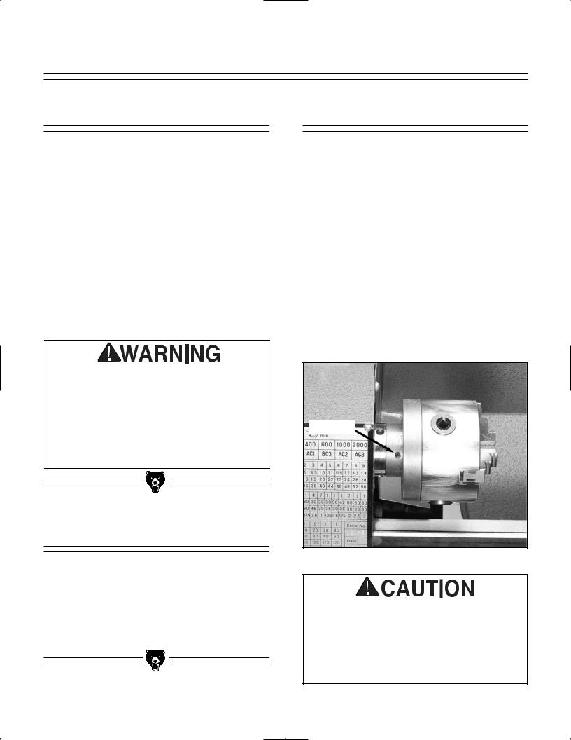
The 3 and 4-jaw chucks have a setscrew in the hub of the back plate. Figure 2. This setscrew prevents the chucks from unscrewing when rotating the lathe in the reverse direction. Prior to removing the chuck, loosen the setscrew in the hub of the back plate.
Setscrew
Figure 2. Typical chuck mounting.
ALWAYS place a piece of plywood over the ways of the lathe before removing or installing a chuck. This helps in providing a flat surface for the chuck to land on, thereby avoiding a potential finger pinch situation.
G4000 9'' x 19'' Lathe |
-9- |
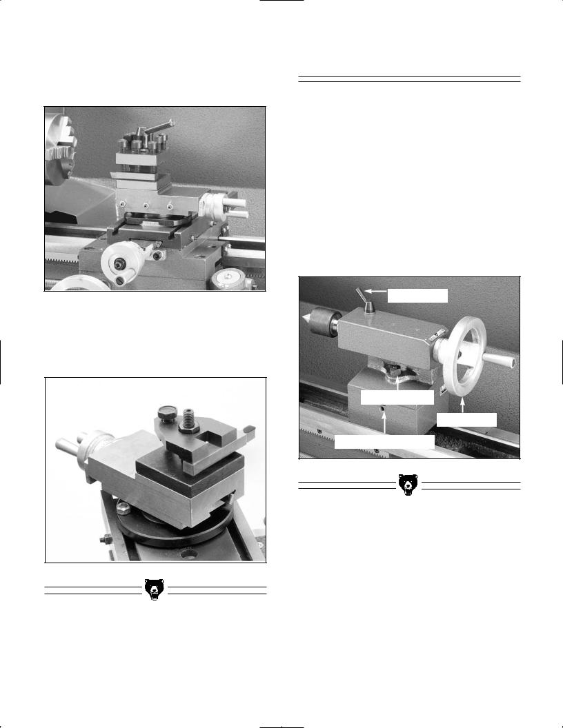
Use the chuck removal bars supplied to remove the 3 or 4-jaw chucks. Figure 3. Use one bar to hold the spindle stationary, the other to unscrew the chuck. Turn the chuck counter-clockwise to remove.
Figure 3. Chuck removal bars in place.
To mount one of the standard chucks, line up the desired chuck (or face plate) with the threaded spindle. Thread the chuck in place. Take care to ensure that the threads on both the headstock and the chuck are clean and free of obstructions before mounting.
Never leave a chuck key or chuck removal bar in the chuck or spindle when they are not in use. If the machine is accidentally started with these in place, they can become projectiles and cause serious injury.
Live Center
The live center is used to support stock which is too long to be supported by the chuck alone. Stock protruding more than three times its diameter should be supported by the live center.
The tailstock barrel and live center have a Morse taper #2. Before assembling these, insure that the mating surfaces are “white glove” clean. These parts will last longer and remain accurate when properly maintained. Insert the end of the live center into the tailstock bore until it seats. The force of a mounted workpiece will fully seat the taper.
When using a live center, the tailstock barrel should protrude about 1⁄2'' and not more than 3''.
See Figure 4.
To remove the live center, back the tailstock barrel all the way into the tailstock casting. The live center will pop out. Be sure to catch it when it comes out to avoid damaging the tip.
Figure 4. Live center installed in tailstock.
-10- |
G4000 9'' x 19'' Lathe |

Steady Rest |
Follow Rest |
The steady rest supports long, small diameter stock that otherwise could not be turned. The steady rest can also replace the tailstock to allow for cutting tool access at the outboard end of your workpiece.
To mount the steady rest :
1.Secure to bedway from below with the locking plate.
2.A single M8-1.25 x 55mm cap screw, along with a nut and washer, holds the steady rest in place. See Figure 5.
3.The sliding fingers on the center steady rest should receive periodic lubrication while in use to prevent premature wear.
Sliding Fingers
Cap Screw 
Figure 5. Steady rest in place.
The follow rest is normally used with small diameter stock to prevent the workpiece from ''springing'' under pressure from the turning tool. To install the follow rest:
1.The follow rest is secured to the saddle with two cap screws. See Figure 6.
2.The sliding fingers on the follow rest are similar to those on the steady rest, and should be lubricated to prevent premature wear.
Cap Screws
Figure 6. Follow rest secured to saddle.
G4000 9'' x 19'' Lathe |
-11- |

SECTION 5: CONTROLS
Spindle Speeds
The rotating speed of the headstock is controlled by the positioning of the belts on the pulleys. See Figure 7. These are accessed by removing the cover on the end of the headstock. Refer to the chart at the end of this manual or the plate on the headstock (Figure 8) to determine which belt combinations produce what speeds. The speed settings available on this machine are 130, 300, 400, 600, 1000 and 2000 RPM.
Idler Pulley
C
B
A
Figure 7. Pulley positions in headstock.
Figure 8. Spindle speed portion of machine plate.
This belt tensioning lever on the top of the headstock loosens the drive belt to enable the operator to change speeds. See Figure 9. The tension release lever can also be used as a clutch while the machine is in operation.
NEVER reach across a rotating chuck or plate. The use of the Belt Tension Release Lever as a clutch should be restricted to those times when starting a heavier part turning and then at very low speed.
Figure 9. Belt tensioning lever.
-12- |
G4000 9'' x 19'' Lathe |

Feed Rate
The lever at the bottom of the headstock changes the feed rate, or the number of threads- per-inch. See Figure 9. The lever can be engaged in any of nine different positions. When used in conjunction with the interchangeable gears supplied it is possible to achieve a wide variety of feed or threading rates.
Figure 10. Feed rate selector lever.
The machine plate describes some of the more typical settings which might be used. Figure 11 shows the feed rate portion of the machine plate. Looking at the first column, this means that a feed rate of .0023'' can be achieved by putting the feed lever in position 9 with a 28 tooth gear installed at A, and 80 tooth gears at B and C.
Threading feed rates are described in Figures 12 and 13. An 8 thread per inch feed is the result of having a 60 tooth gear at A, a 30 tooth gear at B, and the lever in position 1.
A metric 2mm pitch requires the lever to be in position 7 and would use the same A and B gears installed above. However the gear between them changes from a 120 tooth to a 127 tooth. Also note that the alignment of gears A and B are offset so that A now engages the 127 tooth gear and B engages the 120 tooth gear. The shaft for position B is provided with a spacer which can be installed behind the gear to change its position.
Figure 11. Feed rates portion of machine plate.
Figure 12. Threading rates portion of machine plate.
 A
A
C
B
Figure 13. Interchangeable gear positions.
G4000 9'' x 19'' Lathe |
-13- |

Carriage Controls
The carriage allows the cutting tool to move along the length of the lathe bed. The cross slide allows the cutting tool to travel perpendicular to the bed. The carriage features a top slide which allows linear movement of the cutting tool at any preset angle. This section will review the individual controls on the carriage and provide descriptions of their uses.
Longitudinal Handwheel - The Longitudinal Handwheel moves the carriage left or right along the bed. The control is helpful when setting up the machine for turning or when manual movement is desired during turning operations. Figure
14.
Figure 14. Longitudinal handwheel.
Cross Slide Handwheel - The Cross Slide Handwheel moves the top slide toward and away from the work. Turning the dial clockwise moves the slide toward the workpiece. The graduated scale can be adjusted using the same method as the longitudinal scale. Figure 15.
Figure 15. Cross slide handwheel.
Top Slide Handwh l - The Top Slide Handwheel controls the position of the cutting tool relative to the workpiece. The top slide is adjustable for angle as well as longitudinal travel. It can be adjusted a full 360°, if needed. The graduated scale is adjustable using the same method as the other handwheels. Angle adjustment is controlled by cap screws in the base of the top slide. Figure 16.
Figure 16. Top slide handwheel.
-14- |
G4000 9'' x 19'' Lathe |

Feed Selector - Moving this lever upward engages the automatic longitudinal feed. Figure
17.
Figure 17. Longitudinal feed lever.
NOTICE
Do not simultaneously engage the feed lever and the threading lever. Doing so will damage the lathe.
Half Nut Lever - This lever compresses and releases the half nut that engages the leadscrew. The lever is only engaged while turning threads in stock. A lockout device featured in the lever mechanism engages when the feed selector is used. Figure 18.
 Thread Dial
 Lever
Lever
Figure 18. Threading dial and half nut lever.
Threading Dial Indicator - The indicator tells you when to engage the half nut to begin the threading process. Figure 18.
G4000 9'' x 19'' Lathe |
-15- |
Tool post - A four-way tool post is supplied with the Model G4000. Cutting tools can be attached and removed by tightening or loosening the clamping bolt. Figure 19.
Figure 19. Four-way tool post.
Single Tool Holder - A single-tool tool holder is supplied with the Model G4000. A cutting tool can be installed by tightening or loosening the clamping bolt. Figure 20.
Figure 20. Single tool holder.
Tailstock Controls
Tailstock Handwheel - Turning the handwheel advances or retracts the barrel in the tailstock. The graduated scale on the handwheel is adjustable.
Lock Lever - This lever locks the tailstock barrel in place.
Clamping Nut - The clamping nut locks the tailstock in place on the lathe bed.
Adjustment Setscrews - These setscrews are used for aligning the tailstock to the spindle. This is covered in the next section.
Lock Lever
Clamping Nut
Handwheel
Adjustment Screws
Figure 21. Detail of tailstock controls.
-16- |
G4000 9'' x 19'' Lathe |

Test Run |
Notes |
Now that the lathe is securely in place and you’ve read the safety guidelines, it’s time to give the machine a test run.
Before starting the machine, make sure the machine is properly grounded and the Power and Directional Switch is in the ''OFF'' position.
Figure 22.
Figure 22. Power and directional switch.
Inspect the machine to ensure that all hand tools are out of the way, guards are in place and nothing is impeding the movement of the chuck.
Set the switch to position 2. The chuck should be turning in a counterclockwise direction. If the direction is reversed, contact our service department for further instruction. If the lathe is running correctly, take some time to become familiar with the various controls on the Model G4000. The controls will be reviewed by location on the machine, in Section 5.
G4000 9'' x 19'' Lathe |
-17- |
 Loading...