


 Loading...
MODEL G0824
14" X 40" GUNSMITH LATHE
OWNER'S MANUAL
(For models manufactured since 12/16)
COPYRIGHT © MARCH, 2017 BY GRIZZLY INDUSTRIAL, INC. REVISED JULY, 2017 (BL) |
|
WARNING: NO PORTION OF THIS MANUAL MAY BE REPRODUCED IN ANY SHAPE |
|
OR FORM WITHOUT THE WRITTEN APPROVAL OF GRIZZLY INDUSTRIAL, INC. |
|
#BLJHKB18736 PRINTED IN CHINA |
V1.09.17 |

This manual provides critical safety instructions on the proper setup, operation, maintenance, and service of this machine/tool. Save this document, refer to it often, and use it to instruct other operators.
Failure to read, understand and follow the instructions in this manual may result in fire or serious personal injury—including amputation, electrocution, or death.
The owner of this machine/tool is solely responsible for its safe use. This responsibility includes but is not limited to proper installation in a safe environment, personnel training and usage authorization, proper inspection and maintenance, manual availability and comprehension, application of safety devices, cutting/sanding/grinding tool integrity, and the usage of personal protective equipment.
The manufacturer will not be held liable for injury or property damage from negligence, improper training, machine modifications or misuse.
Some dust created by power sanding, sawing, grinding, drilling, and other construction activities contains chemicals known to the State of California to cause cancer, birth defects or other reproductive harm. Some examples of these chemicals are:
•Lead from lead-based paints.
•Crystalline silica from bricks, cement and other masonry products.
•Arsenic and chromium from chemically-treated lumber.
Your risk from these exposures varies, depending on how often you do this type of work. To reduce your exposure to these chemicals: Work in a well ventilated area, and work with approved safety equipment, such as those dust masks that are specially designed to filter out microscopic particles.
Table of Contents
INTRODUCTION................................................ |
2 |
Contact Info.................................................... |
2 |
Manual Accuracy............................................ |
2 |
Identification................................................... |
3 |
Controls & Components................................. |
4 |
Machine Data Sheet....................................... |
7 |
SECTION 1: SAFETY...................................... |
10 |
Safety Instructions for Machinery................. |
10 |
Additional Safety for Metal Lathes............... |
12 |
Additional Chuck Safety............................... |
13 |
SECTION 2: POWER SUPPLY....................... |
14 |
SECTION 3: SETUP........................................ |
16 |
Preparation................................................... |
16 |
Unpacking..................................................... |
16 |
Needed for Setup......................................... |
16 |
Inventory....................................................... |
17 |
Cleanup........................................................ |
18 |
Site Considerations...................................... |
19 |
Assembly...................................................... |
20 |
Lifting & Placing............................................ |
21 |
Anchoring to Floor........................................ |
22 |
Leveling........................................................ |
23 |
Lubricating Lathe.......................................... |
23 |
Adding Coolant............................................. |
23 |
Power Connection........................................ |
24 |
Test Run....................................................... |
25 |
Spindle Break-In........................................... |
27 |
SECTION 4: OPERATIONS............................ |
28 |
Operation Overview...................................... |
28 |
Chuck & Faceplate Mounting....................... |
29 |
Camlock Stud Installation............................. |
29 |
Chuck Safety & Support Devices................. |
30 |
Chuck Installation......................................... |
30 |
Chuck Removal............................................ |
32 |
Scroll Chuck Clamping................................. |
32 |
Chuck Jaw Reversal..................................... |
33 |
4-Jaw Chuck................................................. |
33 |
Faceplate...................................................... |
34 |
Tailstock....................................................... |
35 |
Centers......................................................... |
39 |
Drill Chuck & Arbor....................................... |
42 |
Steady Rest.................................................. |
42 |
Follow Rest................................................... |
43 |
Carriage & Compound Locks....................... |
44 |
Compound Rest............................................ |
44 |
Tool Post...................................................... |
45 |
Spindle Spider.............................................. |
46 |
Manual Feed................................................. |
47 |
Spindle Speed.............................................. |
48 |
Power Feed.................................................. |
49 |
End Gears.................................................... |
52 |
Threading..................................................... |
54 |
Coolant System............................................ |
58 |
SECTION 5: ACCESSORIES.......................... |
59 |
SECTION 6: MAINTENANCE......................... |
63 |
Schedule....................................................... |
63 |
Cleaning/Protecting...................................... |
63 |
Lubrication.................................................... |
64 |
Coolant System Service............................... |
69 |
Machine Storage.......................................... |
71 |
SECTION 7: SERVICE.................................... |
72 |
Troubleshooting............................................ |
72 |
Backlash Adjustment.................................... |
75 |
Leadscrew End-Play Adjustment................. |
76 |
Gib Adjustment............................................. |
76 |
Half Nut Adjustment..................................... |
78 |
V-Belt Tension & Replacement.................... |
79 |
Leadscrew Shear Pin Replacement............. |
80 |
Feed Clutch Adjustment............................... |
81 |
Gap Insert Removal & Installation................ |
82 |
Bearing Preload............................................ |
83 |
SECTION 8: WIRING...................................... |
86 |
Wiring Safety Instructions............................. |
86 |
Wiring Overview........................................... |
87 |
Electrical Cabinet Wiring.............................. |
88 |
Electrical Cabinet.......................................... |
89 |
Main & Pump Motor Wiring.......................... |
90 |
Control Panel Wiring.................................... |
91 |
SECTION 9: PARTS........................................ |
92 |
Headstock Case & Shift............................... |
92 |
Headstock Drive........................................... |
94 |
Headstock Spindle........................................ |
96 |
Change Gears.............................................. |
98 |
Quick Change Gearbox................................ |
99 |
Apron.......................................................... |
101 |
Cross Slide................................................. |
103 |
Compound Slide & Tool Post..................... |
105 |
Steady & Follow Rests............................... |
106 |
Tailstock..................................................... |
107 |
Pump.......................................................... |
108 |
Motor & Feed Rod...................................... |
109 |
Cabinet & Brake......................................... |
111 |
Main Electrical Breakdown......................... |
113 |
Digital Readout........................................... |
114 |
Accessories................................................ |
116 |
Labels & Cosmetics.................................... |
117 |
SECTION 10: APPENDIX............................. |
118 |
Threading & Feed Charts........................... |
118 |
WARRANTY & RETURNS............................ |
121 |
INTRODUCTION
Contact Info |
|
Manual Accuracy |
|
|
|
|
|
|
We stand behind our machines! If you have questions or need help, contact us with the information below. Before contacting, make sure you get the serial number and manufacture date from the machine ID label. This will help us help you faster.
Grizzly Technical Support
1815 W. Battlefield
Springfield, MO 65807
Phone: (570) 546-9663 Email: techsupport@grizzly.com
We want your feedback on this manual. What did you like about it? Where could it be improved? Please take a few minutes to give us feedback.
Grizzly Documentation Manager
P.O. Box 2069
Bellingham, WA 98227-2069
Email: manuals@grizzly.com
We are proud to provide a high-quality owner’s manual with your new machine!
We made every effort to be exact with the instructions, specifications, drawings, and photographs in this manual. Sometimes we make mistakes, but our policy of continuous improvement also means that sometimes the machine you receive is slightly different than shown in the manual.
If you find this to be the case, and the difference between the manual and machine leaves you confused or unsure about something, check our website for an updated version. We post current manuals and manual updates for free on our website at www.grizzly.com.
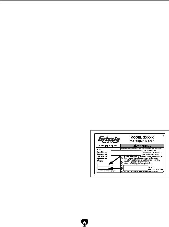
Alternatively, you can call our Technical Support for help. Before calling, make sure you write down the Manufacture Date and Serial Number from the machine ID label (see below). This information is required for us to provide proper tech support, and it helps us determine if updated documentation is available for your machine.
Manufacture Date |
Serial Number |
-2- |
Model G0824 (Mfd. Since 12/16) |
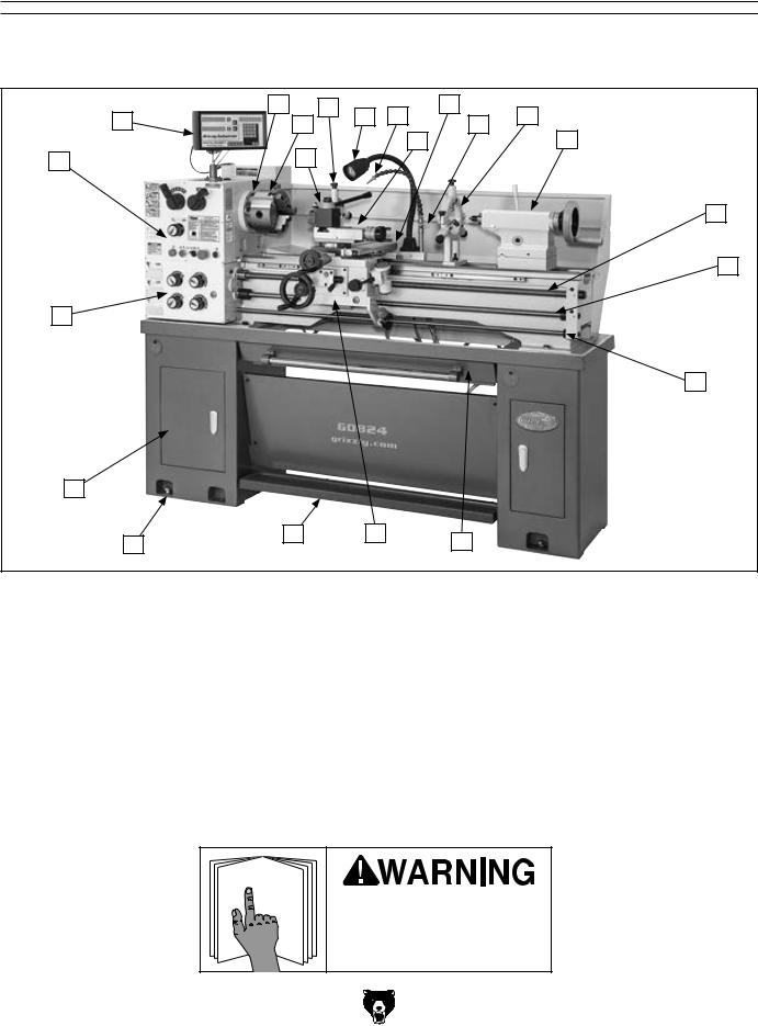
Identification
Become familiar with the names and locations of the controls and features shown below to better understand the instructions in this manual.
C |
|
F |
G |
H |
J |
|
L |
B |
D |
|
|
K |
|||
|
|
I |
|
M |
|||
|
E |
|
|
|
|
||
A |
|
|
|
|
|
|
|
|
|
|
|
|
|
|
N |
|
|
|
|
|
|
|
O |
V |
|
|
|
|
|
|
|
|
|
|
|
|
|
|
P |
U |
|
|
|
|
|
|
|
T |
S |
|
R |
|
|
Q |
|
|
|
|
|
|
|
A. |
Headstock Controls (see Page 4 for details) |
M. |
Tailstock (see Page 5 for details) |
B. |
DRO Unit |
N. |
Longitudinal Leadscrew |
C. |
D1-5 Camlock MT#5 Spindle |
O. |
Feed Rod |
D. |
3-Jaw Chuck 7" |
P. |
Control Rod |
E. |
Quick-Change Tool Post |
Q. |
Chip Tray |
F. |
Follow Rest |
R. |
Carriage (see Page 5 for details) |
G. |
LED Work Lamp |
S. |
Foot Brake |
H. |
Coolant Nozzle |
T. |
Stand Mounting Points |
I. |
Compound Rest |
U. |
Storage Cabinet |
J. |
Cross Slide |
V. |
Quick-Change Gearbox Controls (see Page |
K. |
Coolant Valve |
|
4 for details) |
L.Steady Rest
To reduce your risk of serious injury, read this entire manual BEFORE using machine.
Model G0824 (Mfd. Since 12/16) |
-3- |
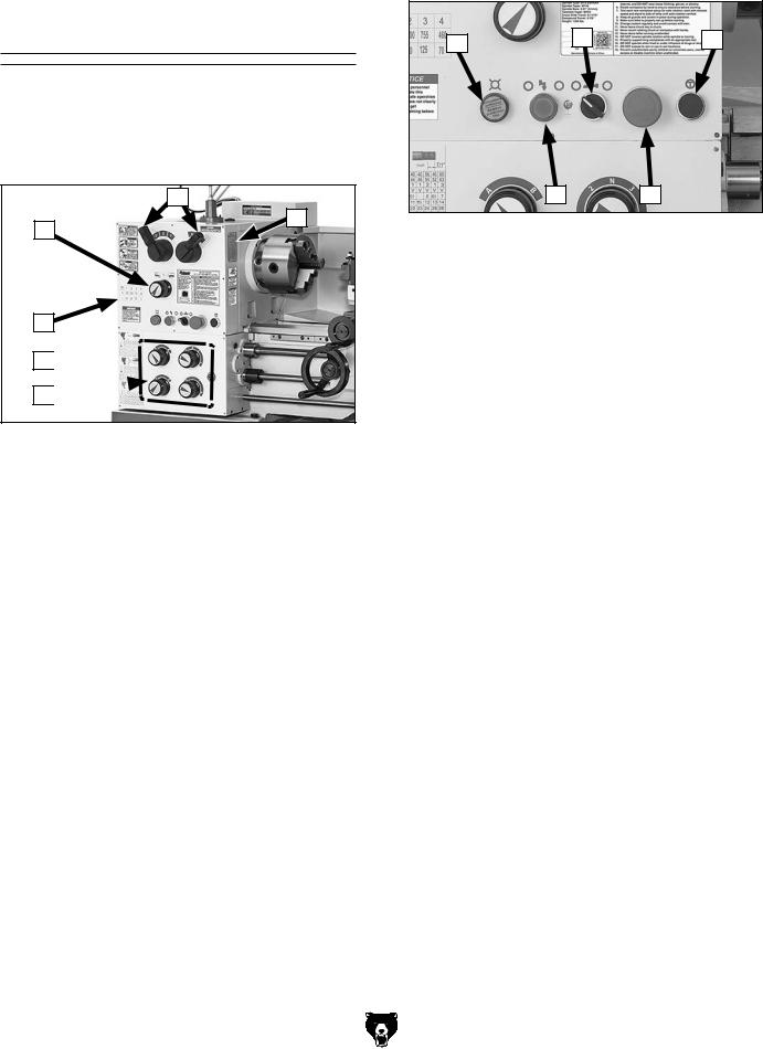
Controls &
Components
Refer to Figures 1–7 and the following descriptions to become familiar with the basic controls of this lathe.
Headstock
A
F
B
C
D
E
Figure 1. Headstock controls.
A.Spindle Speed and Speed Range Levers:
The spindle speed lever (left) and spindle speed range lever (right) are used in conjunction with each other to select one of the eight available spindle speeds.
B.Feed Direction Dial: Changes direction of leadscrew/feed rod rotation (i.e. direction of carriage travel) without reversing direction of spindle rotation. Typically used for left-hand threading.
C.Spindle Speed Chart: Displays configuration of the spindle speed levers for each of the eight spindle speeds.
D.Thread and Feed Charts: Display the configuration of the gearbox dials and end gears to produce all available threading or feeding options.
E.Quick-Change Gearbox Dials: Control the leadscrew and feed rod speed for threading and feeding operations.
F.Thread Dial Chart: Indicates where on the thread dial to engage the half nut when cutting inch threads.
-4-
Control Panel
G |
I |
K |
H J
Figure 2. Control panel.
G.Power Light: Indicates lathe controls are receiving power. Illuminates when Emergency Stop/RESET button is reset.
H.Power Button: Enables the spindle motor when the Emergency Stop/RESET button is reset.
I. Coolant Pump Switch: Controls coolant pump motor.
J.Emergency Stop/RESET Button: Stops all machine functions. Twist clockwise to reset.
K.Jog/Inching Button: Starts forward spindle rotation as long as it is pressed.
Model G0824 (Mfd. Since 12/16)
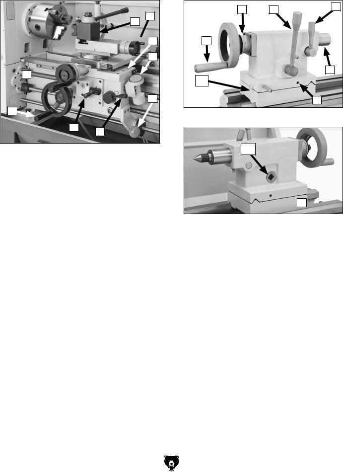
Carriage
M
L

 N
N
O
T

 P S
P S 

R Q
Figure 3. Carriage controls.
L.Quick-Change Tool Post: Allows the operator to quickly load and unload tools/ tool holders.
M.Compound Rest Handwheel: Moves the tool toward and away from the workpiece at the preset angle of the compound rest. Dial is graduated in increments of 0.001" (0.100" per full revolution).
N.Carriage Lock: Secures the carriage in place for greater rigidity and cutting accuracy when it should not move.
O.Thread Dial: Indicates when to engage the half nut during threading operations.
P.Spindle Lever: Starts, stops, and reverses direction of spindle rotation.
Q . Half Nut Lever: Engages/disengages the half nut for threading operations.
R.Feed Selection Lever: Selects the carriage or cross slide for power feed.
S.Carriage Handwheel: Moves the carriage along the bed. Dial is graduated in increments of 0.005" (0.56" per full revolution).
T.Cross Slide Handwheel: Moves the cross slide toward and away from the workpiece. Dial is graduated in increments of 0.002" (0.200" per full revolution).
Model G0824 (Mfd. Since 12/16)
Tailstock
V |
W |
X |
|
U
Y
AA
Z
Figure 4. Tailstock controls.
AB

 Z
Z
Figure 5. Additional tailstock controls.
U.Quill Handwheel: Moves the quill toward or away from the spindle.
V.Graduated Scale: Indicates quill movement in increments of 0.001", with one full revolution equaling 0.100" of quill travel.
W.Tailstock Lock Lever: Secures the tailstock in position along the bedway.
X.Quill Lock Lever: Secures the quill in position.
Y.Quill: Moves toward and away from the spindle. Holds centers and tooling.
Z.Tailstock Offset Screws: Adjusts the tailstock offset left or right from the spindle centerline (1 of 2).
AA.Offset Scale: Indicates the relative distance of tailstock offset from the spindle centerline.
AB. 1⁄2" Square-Drive Lock-Down: Used with a torque wrench for precise alignment of centers.
-5-
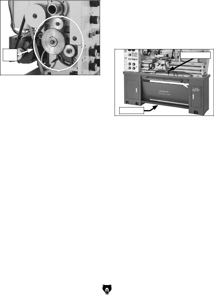
End Gears
End
Gears
Figure 6. End gear components.
Configuring the end gears (shown in Figure 6) controls the speed of the leadscrew for threading, or the feed rod for power feed operations.
-6-
Safety Foot Brake
This lathe is equipped with a foot brake (see Figure 7) to quickly stop the spindle instead of allowing it to coast to a stop on its own. Pushing the foot brake while the spindle is ON cuts power to the motor and stops the spindle. After the foot brake is used, the spindle lever must be returned to the OFF (middle) position to reset the spindle switches before re-starting spindle rotation.
Spindle Lever |
Foot Brake |
Figure 7. Foot brake and spindle lever.
Model G0824 (Mfd. Since 12/16)

MACHINE DATA
SHEET
Customer Service #: (570) 546-9663 · To Order Call: (800) 523-4777 · Fax #: (800) 438-5901
MODEL G0824 14" X 40" GUNSMITH LATHE WITH 2"
SPINDLE BORE
Product Dimensions: |
|
Weight............................................................................................................................................................ |
1300 lbs. |
Width (side-to-side) x Depth (front-to-back) x Height..................................................................... |
78 x 31 x 61-1/2 in. |
Footprint (Length x Width)............................................................................................................................ |
71 x 16 in. |
Shipping Dimensions: |
|
Type.......................................................................................................................................................... |
Wood Crate |
Content........................................................................................................................................................... |
Machine |
Weight............................................................................................................................................................ |
1550 lbs. |
Length x Width x Height....................................................................................................................... |
76 x 33 x 61 in. |
Must Ship Upright................................................................................................................................................... |
Yes |
Electrical: |
|
Power Requirement........................................................................................................... |
220V, Single-Phase, 60 Hz |
Full-Load Current Rating................................................................................................................................... |
10.45A |
Minimum Circuit Size.............................................................................................................................................. |
15A |
Connection Type....................................................................................................................................... |
Cord & Plug |
Power Cord Included.............................................................................................................................................. |
Yes |
Power Cord Length................................................................................................................................................. |
6 ft. |
Power Cord Gauge......................................................................................................................................... |
14 AWG |
Plug Included.......................................................................................................................................................... |
Yes |
Included Plug Type................................................................................................................................................ |
6-15 |
Switch Type............................................................................................ |
Control Panel w/Magnetic Switch Protection |
Motors: |
|
Coolant Pump |
|
Horsepower................................................................................................................................................. |
40W |
Phase............................................................................................................................................ |
Single-Phase |
Amps......................................................................................................................................................... |
0.45A |
Type........................................................................................................................................... |
TEFC Induction |
Power Transfer ............................................................................................................................... |
Direct Drive |
Bearings..................................................................................................... |
Shielded & Permanently Lubricated |
Main |
|
Horsepower............................................................................................................................................. |
2.5 HP |
Phase............................................................................................................................................ |
Single-Phase |
Amps............................................................................................................................................................ |
10A |
Speed................................................................................................................................................ |
1720 RPM |
Type................................................................................................................. |
TEFC Capacitor-Start Induction |
Power Transfer .................................................................................................................................. |
Belt Drive |
Bearings..................................................................................................... |
Shielded & Permanently Lubricated |
Model G0824 (Mfd. Since 12/16) |
-7- |

Main Specifications: |
|
Operation Info |
|
Swing Over Bed......................................................................................................................................... |
14 in. |
Distance Between Centers........................................................................................................................ |
40 in. |
Swing Over Cross Slide..................................................................................................................... |
8-13/16 in. |
Swing Over Saddle.......................................................................................................................... |
13-13/16 in. |
Swing Over Gap.................................................................................................................................. |
19-3/4 in. |
Maximum Tool Bit Size............................................................................................................................. |
5/8 in. |
Compound Travel.................................................................................................................................. |
3-7/8 in. |
Carriage Travel.......................................................................................................................................... |
36 in. |
Cross Slide Travel............................................................................................................................. |
6-11/16 in. |
Headstock Info |
|
Spindle Bore.............................................................................................................................. |
2.01 in. (51mm) |
Spindle Taper............................................................................................................................................ |
MT#6 |
Number of Spindle Speeds............................................................................................................................... |
8 |
Spindle Speeds......................................................................................................................... |
70 – 2000 RPM |
Spindle Type................................................................................................................................ |
D1-5 Camlock |
Spindle Bearings................................................................................................ |
High-Precision Tapered Roller |
Spindle Length..................................................................................................................................... |
17-1/4 in. |
Spindle Length with 3-Jaw Chuck.............................................................................................................. |
22 in. |
Spindle Length with 4-Jaw Chuck....................................................................................................... |
21-1/2 in. |
Spindle Length with Faceplate............................................................................................................ |
20-1/2 in. |
Tailstock Info |
|
Tailstock Quill Travel......................................................................................................................... |
3-15/16 in. |
Tailstock Taper.......................................................................................................................................... |
MT#3 |
Tailstock Barrel Diameter.................................................................................................................. |
1-21/32 in. |
Threading Info |
|
Number of Longitudinal Feeds....................................................................................................................... |
32 |
Range of Longitudinal Feeds.......................................................................................... |
0.002 – 0.0548 in./rev. |
Number of Cross Feeds................................................................................................................................. |
32 |
Range of Cross Feeds.................................................................................................. |
0.0007 – 0.0187 in./rev. |
Number of Inch Threads................................................................................................................................. |
34 |
Range of Inch Threads...................................................................................................................... |
4 – 56 TPI |
Number of Metric Threads.............................................................................................................................. |
26 |
Range of Metric Threads.................................................................................................................. |
0.4 – 7 mm |
Dimensions |
|
Bed Width.............................................................................................................................................. |
7-3/8 in. |
Carriage Leadscrew Diameter.................................................................................................................. |
7/8 in. |
Leadscrew TPI........................................................................................................................................... |
8 TPI |
Carriage Leadscrew Length....................................................................................................................... |
50 in. |
Steady Rest Capacity................................................................................................................... |
3/8 – 2-3/4 in. |
Follow Rest Capacity.................................................................................................................... |
3/8 – 2-3/8 in. |
Faceplate Size..................................................................................................................................... |
12-1/2 in. |
Feed Rod Diameter.................................................................................................................................. |
3/4 in. |
Floor to Center Height......................................................................................................................... |
45-1/2 in. |
Construction |
|
Headstock............................................................................................................................................ |
Cast Iron |
End Gears...................................................................................................................... |
Flame-Hardened Steel |
Bed...................................................................................................................... |
Induction-Hardened Cast Iron |
Body..................................................................................................................................................... |
Cast Iron |
Stand.......................................................................................................................................................... |
Steel |
Paint Type/Finish...................................................................................................................................... |
Epoxy |
-8- |
Model G0824 (Mfd. Since 12/16) |
Fluid Capacities |
|
Headstock Capacity.................................................................................................................................. |
3.5 qt. |
Headstock Fluid Type............................................................. |
ISO 32 (e.g. Grizzly T23963, Mobile DTE Light) |
Gearbox Capacity..................................................................................................................................... |
24 oz. |
Gearbox Fluid Type................................................................... |
ISO 68 (e.g. Grizzly T23962, Mobile Vactra 2) |
Apron Capacity........................................................................................................................................... |
7 oz. |
Apron Fluid Type....................................................................... |
ISO 68 (e.g. Grizzly T23962, Mobile Vactra 2) |
Coolant Capacity....................................................................................................................................... |
10 qt. |
Other Specifications: |
|
Country of Origin ................................................................................................................................................ |
China |
Warranty ........................................................................................................................................................... |
1 Year |
Approximate Assembly & Setup Time ............................................................................................................. |
2 Hours |
Serial Number Location .................................................................................................................................. |
ID Label |
Sound Rating ..................................................................................................................................................... |
82 dB |
ISO 9001 Factory .................................................................................................................................................. |
Yes |
Certified by a Nationally Recognized Testing Laboratory (NRTL) .......................................................................... |
No |
Features: |
|
X- & Z-Axis DRO |
|
Removable Bed Gap |
|
Quick-Change Spindle Speed and Gearbox Controls |
|
On/Off Reverse Spindle Switch on Carriage |
|
Adjustable Halogen Work Light |
|
Steady and Follow Rests with Roller Bearing Supports |
|
Outboard Spindle Support Spider with 4 Brass-Tipped Bolts |
|
Foot Brake with Motor Shut-Off Switch |
|
Built-In Coolant System |
|
D1-5 Camlock Spindle Nose |
|
7 in. 3-Jaw Chuck and 8 in. 4-Jaw Chuck |
|
Pull-Out Chip Tray |
|
Full-Length Splash Guard |
|
200-Series Quick-Change Tool Post |
|
Accessories Included: |
|
7 in. 3-Jaw Universal Chuck with 2 Sets of Jaws |
|
8 in. 4-Jaw Independent Chuck with Reversible Jaws |
|
Steady and Follow Rests with Roller Bearing Supports |
|
12-1/2 in. Faceplate |
|
Carbide-Tipped MT#3 Dead Center |
|
Standard MT#3 Dead Center |
|
Set of 8 Change Gears |
|
1/2" Drill Chuck w/MT#3 Arbor |
|
MT#6-MT#3 Adapter Sleeve |
|
Toolbox with Service Tools |
|
Model G0824 (Mfd. Since 12/16) |
-9- |

SECTION 1: SAFETY
For Your Own Safety, Read Instruction Manual Before Operating This Machine
The purpose of safety symbols is to attract your attention to possible hazardous conditions. This manual uses a series of symbols and signal words intended to convey the level of importance of the safety messages. The progression of symbols is described below. Remember that safety messages by themselves do not eliminate danger and are not a substitute for proper accident prevention measures. Always use common sense and good judgment.
|
|
Indicates an imminently hazardous situation which, if not avoided, |
|
|
|
|
|
WILL result in death or serious injury. |
|
|
Indicates a potentially hazardous situation which, if not avoided, |
|
|
|
|
|
COULD result in death or serious injury. |
|
|
|
|
|
Indicates a potentially hazardous situation which, if not avoided, |
|
|
|
|
|
MAY result in minor or moderate injury. It may also be used to alert |
|
|
|
|
|
against unsafe practices. |
NOTICE |
This symbol is used to alert the user to useful information about |
|
proper operation of the machine. |
||
Safety Instructions for Machinery
OWNER’S MANUAL. Read and understand this owner’s manual BEFORE using machine.
TRAINED OPERATORS ONLY. Untrained operators have a higher risk of being hurt or killed. Only allow trained/supervised people to use this machine. When machine is not being used, disconnect power, remove switch keys, or lock-out machine to prevent unauthorized use—especially around children. Make your workshop kid proof!
DANGEROUS ENVIRONMENTS. Do not use machinery in areas that are wet, cluttered, or have poor lighting. Operating machinery in these areas greatly increases the risk of accidents and injury.
MENTAL ALERTNESS REQUIRED. Full mental alertness is required for safe operation of machinery. Never operate under the influence of drugs or alcohol, when tired, or when distracted.
ELECTRICAL EQUIPMENT INJURY RISKS. You can be shocked, burned, or killed by touching live electrical components or improperly grounded machinery. To reduce this risk, only allow qualified service personnel to do electrical installation or repair work, and always disconnect power before accessing or exposing electrical equipment.
DISCONNECT POWER FIRST. Always disconnect machine from power supply BEFORE making adjustments, changing tooling, or servicing machine. This prevents an injury risk from unintended startup or contact with live electrical components.
EYE PROTECTION. Always wear ANSI-approved safety glasses or a face shield when operating or observing machinery to reduce the risk of eye injury or blindness from flying particles. Everyday eyeglasses are NOT approved safety glasses.
-10- |
Model G0824 (Mfd. Since 12/16) |

WEARING PROPER APPAREL. Do not wear clothing, apparel or jewelry that can become entangled in moving parts. Always tie back or cover long hair. Wear non-slip footwear to reduce risk of slipping and losing control or accidentally contacting cutting tool or moving parts.
HAZARDOUS DUST. Dust created by machinery operations may cause cancer, birth defects, or long-term respiratory damage. Be aware of dust hazards associated with each workpiece material. Always wear a NIOSH-approved respirator to reduce your risk.
HEARING PROTECTION. Always wear hearing protection when operating or observing loud machinery. Extended exposure to this noise without hearing protection can cause permanent hearing loss.
REMOVE ADJUSTING TOOLS. Tools left on machinery can become dangerous projectiles upon startup. Never leave chuck keys, wrenches, or any other tools on machine. Always verify removal before starting!
USE CORRECT TOOL FOR THE JOB. Only use this tool for its intended purpose—do not force it or an attachment to do a job for which it was not designed. Never make unapproved modifica- tions—modifying tool or using it differently than intended may result in malfunction or mechanical failure that can lead to personal injury or death!
AWKWARD POSITIONS. Keep proper footing and balance at all times when operating machine. Do not overreach! Avoid awkward hand positions that make workpiece control difficult or increase the risk of accidental injury.
CHILDREN & BYSTANDERS. Keep children and bystanders at a safe distance from the work area. Stop using machine if they become a distraction.
GUARDS & COVERS. Guards and covers reduce accidental contact with moving parts or flying debris. Make sure they are properly installed, undamaged, and working correctly BEFORE operating machine.
FORCING MACHINERY. Do not force machine. It will do the job safer and better at the rate for which it was designed.
NEVER STAND ON MACHINE. Serious injury may occur if machine is tipped or if the cutting tool is unintentionally contacted.
STABLE MACHINE. Unexpected movement during operation greatly increases risk of injury or loss of control. Before starting, verify machine is stable and mobile base (if used) is locked.
USE RECOMMENDED ACCESSORIES. Consult this owner’s manual or the manufacturer for recommended accessories. Using improper accessories will increase the risk of serious injury.
UNATTENDED OPERATION. To reduce the risk of accidental injury, turn machine OFF and ensure all moving parts completely stop before walking away. Never leave machine running while unattended.
MAINTAIN WITH CARE. Follow all maintenance instructions and lubrication schedules to keep machine in good working condition. A machine that is improperly maintained could malfunction, leading to serious personal injury or death.
DAMAGED PARTS. Regularly inspect machine for damaged, loose, or mis-adjusted parts—or any condition that could affect safe operation. Immediately repair/replace BEFORE operating machine. For your own safety, DO NOT operate machine with damaged parts!
MAINTAIN POWER CORDS. When disconnecting cord-connected machines from power, grab and pull the plug—NOT the cord. Pulling the cord may damage the wires inside. Do not handle cord/plug with wet hands. Avoid cord damage by keeping it away from heated surfaces, high traffic areas, harsh chemicals, and wet/damp locations.
EXPERIENCING DIFFICULTIES. If at any time you experience difficulties performing the intended operation, stop using the machine! Contact our Technical Support at (570) 546-9663.
Model G0824 (Mfd. Since 12/16) |
-11- |

Additional Safety for Metal Lathes
Serious injury or death can occur from getting entangled in, crushed between, or struck by rotating parts on a lathe! Unsecured tools or workpieces that fly loose from rotating objects can also strike nearby operators with deadly force. To minimize the risk of getting hurt or killed, anyone operating this machine MUST completely heed the hazards and warnings below.
CLOTHING, JEWELRY & LONG HAIR. Tie back long hair, remove jewelry, and do not wear loose clothing or gloves. These can easily get caught on rotating parts and pull you into lathe.
ROTATING PARTS. Always keep hands and body at a safe distance from rotating parts—especially those with projecting surfaces. Never hold anything against rotating workpiece, such as emery cloth, that can pull you into lathe.
GUARDING. Guards and covers protect against entanglement or flying objects. Always ensure they are properly installed while machine is running.
ADJUSTMENT TOOLS. Remove all chuck keys, wrenches, and adjustment tools before turning lathe ON. A tool left on the lathe can become a deadly projectile when spindle is started.
SAFE CLEARANCES. Before starting spindle, verify workpiece has adequate clearance by handrotating it through its entire range of motion.
NEW SETUPS. Test each new setup by starting spindle rotation at the lowest speed and standing to the side of the lathe until workpiece reaches full speed and you can verify safe rotation.
SPINDLE SPEEDS. Using spindle speeds that are too fast for the workpiece or clamping equipment can cause rotating parts to come loose and strike nearby people with deadly force. Always use slow spindle speeds with large or non-concentric workpieces. Never exceed rated RPM of the chuck.
LONG STOCK SAFETY. Long stock can whip violently if not properly supported. Always support any stock that extends from the chuck/headstock more than three times its own diameter.
CLEARING CHIPS. Metal chips can be razor sharp. Avoid clearing them by hand or with a rag. Use a brush or vacuum instead.
SECURE WORKPIECE. An improperly secured workpiece can fly off spindle with deadly force. Make sure workpiece is properly secured before starting the lathe.
CHUCKS. Chucks can be heavy and difficult to hold. During installation and removal, protect your hands and precision bed ways by using a chuck cradle or piece of plywood over the bed ways. Use lifting equipment, as necessary, for large chucks.
STOPPING SPINDLE. Always allow spindle to completely stop on its own, or use a brake, if provided. Never put hands or another object on a spinning workpiece to make it stop faster.
CRASHING. A serious explosion of metal parts can occur if cutting tool or other lathe component hits rotating chuck or a projecting part of workpiece. Resulting metal fragments can strike nearby people and lathe will be seriously damaged. To reduce risk of crashing, ALWAYS release automatic feeds after use, NEVER leave lathe unattended, and CHECK all clearances before starting lathe.
COOLANT SAFETY. Coolant can become very toxic through prolonged use and aging. To minimize toxicity, change coolant regularly. When using, position nozzle properly to avoid splashing operator or causing a slipping hazard on floor.
TOOL SELECTION. Cutting with incorrect or dull tooling increases risk of injury from broken or dislodged components, or as a result of extra force required for operation. Always use sharp tooling that is right for the job.
SANDING/POLISHING. To reduce risk of entanglement, never wrap emery cloth around rotating workpiece. Instead, use emery cloth with the aid of a tool or backing board.
MEASURING WORKPIECE. To reduce risk of entanglement, never measure rotating workpieces.
-12- |
Model G0824 (Mfd. Since 12/16) |

Additional Chuck Safety
ENTANGLEMENT. Entanglement with a rotating chuck can lead to death, amputation, broken bones, or other serious injury. Never attempt to slow or stop the lathe chuck by hand, and always roll up long sleeves, tie back long hair, and remove any jewelry or loose apparel BEFORE operating.
CHUCK SPEED RATING. Excessive spindle speeds greatly increase the risk of the workpiece or chuck being thrown from the machine with deadly force. Never use spindle speeds faster than the chuck RPM rating or the safe limits of your workpiece.
USING CORRECT EQUIPMENT. Many workpieces can only be safely turned in a lathe if additional support equipment, such as a tailstock or steady/ follow rest, is used. If the operation is too hazardous to be completed with the lathe or existing equipment, the operator must have enough experience to know when to use a different machine or find a safer way.
TRAINED OPERATORS ONLY. Using a chuck incorrectly can result in workpieces coming loose at high speeds and striking the operator or bystanders with deadly force. To reduce the risk of this hazard, read and understand this document and seek additional training from an experienced chuck user before using a chuck.
CHUCK CAPACITY. Avoid exceeding the capacity of the chuck by clamping an oversized workpiece. If the workpiece is too large to safely clamp with the chuck, use a faceplate or a larger chuck if possible. Otherwise, the workpiece could be thrown from the lathe during operation, resulting in serious impact injury or death.
CLAMPING FORCE. Inadequate clamping force can lead to the workpiece being thrown from the chuck and striking the operator or bystanders. Maximum clamping force is achieved when the chuck is properly maintained and lubricated, all jaws are fully engaged with the workpiece, and the maximum chuck clamping diameter is not exceeded.
PROPER MAINTENANCE. All chucks must be properly maintained and lubricated to achieve maximum clamping force and withstand the rigors of centrifugal force. To reduce the risk of a thrown workpiece, follow all maintenance intervals and instructions in this document.
DISCONNECT POWER. Serious entanglement or impact injuries could occur if the lathe is started while you are adjusting, servicing, or installing the chuck. Always disconnect the lathe from power before performing these procedures.
Model G0824 (Mfd. Since 12/16) |
-13- |
SECTION 2: POWER SUPPLY
Availability
Before installing the machine, consider the availability and proximity of the required power supply circuit. If an existing circuit does not meet the requirements for this machine, a new circuit must be installed. To minimize the risk of electrocution, fire, or equipment damage, installation work and electrical wiring must be done by an electrician or qualified service personnel in accordance with all applicable codes and standards.
Electrocution, fire, shock, or equipment damage may occur if machine is not properly grounded and connected to power supply.
Full-Load Current Rating
The full-load current rating is the amperage a machine draws at 100% of the rated output power. On machines with multiple motors, this is the amperage drawn by the largest motor or sum of all motors and electrical devices that might operate at one time during normal operations.
Full-Load Current Rating at 220V.10.45 Amps
The full-load current is not the maximum amount of amps that the machine will draw. If the machine is overloaded, it will draw additional amps beyond the full-load rating.
If the machine is overloaded for a sufficient length of time, damage, overheating, or fire may result— especially if connected to an undersized circuit. To reduce the risk of these hazards, avoid overloading the machine during operation and make sure it is connected to a power supply circuit that meets the specified circuit requirements.
-14-
Circuit Requirements for 220V
This machine is prewired to operate on a power supply circuit that has a verified ground and meets the following requirements:
Nominal Voltage.......... |
208V, 220V, 230V, 240V |
|
Cycle........................................................... |
|
60 Hz |
Phase..................................................... |
|
1-Phase |
Power Supply Circuit.......................... |
15 Amps |
|
Plug/Receptacle.............................. |
NEMA 6-15 |
|
Cord......... |
“S”-Type, 3-Wire, 14 AWG, 300 VAC |
|
A power supply circuit includes all electrical equipment between the breaker box or fuse panel in the building and the machine. The power supply circuit used for this machine must be sized to safely handle the full-load current drawn from the machine for an extended period of time. (If this machine is connected to a circuit protected by fuses, use a time delay fuse marked D.)
For your own safety and protection of property, consult an electrician if you are unsure about wiring practices or electrical codes in your area.
Note: Circuit requirements in this manual apply to a dedicated circuit—where only one machine will be running on the circuit at a time. If machine will be connected to a shared circuit where multiple machines may be running at the same time, consult an electrician or qualified service personnel to ensure circuit is properly sized for safe operation.
Model G0824 (Mfd. Since 12/16)

Grounding Instructions
This machine MUST be grounded. In the event of certain malfunctions or breakdowns, grounding reduces the risk of electric shock by providing a path of least resistance for electric current.
The power cord and plug specified under “Circuit
Requirements for 220V” on the previous page has an equipment-grounding wire and a grounding prong. The plug must only be inserted into a matching receptacle (outlet) that is properly installed and grounded in accordance with all local codes and ordinances (see figure below).
GROUNDED  6-15 RECEPTACLE
Current Carrying Prongs
6-15 PLUG
Grounding Prong
Figure 8. Typical 6-15 plug and receptacle.
Serious injury could occur if you connect machine to power before completing setup process. DO NOT connect to power until instructed later in this manual.
No adapter should be used with plug. If plug does not fit available receptacle, or if machine must be reconnected for use on a different type of circuit, reconnection must be performed by an electrician or qualified service personnel, and it must comply with all local codes and ordinances.
Model G0824 (Mfd. Since 12/16)
Improper connection of the equipment-grounding wire can result in a risk of electric shock. The wire with green insulation (with or without yellow stripes) is the equipment-grounding wire. If repair or replacement of the power cord or plug is necessary, do not connect the equipment-grounding wire to a live (current carrying) terminal.
Check with a qualified electrician or service personnel if you do not understand these grounding requirements, or if you are in doubt about whether the tool is properly grounded. If you ever notice that a cord or plug is damaged or worn, disconnect it from power, and immediately replace it with a new one.
Extension Cords
We do not recommend using an extension cord with this machine. If you must use an extension cord, only use it if absolutely necessary and only on a temporary basis.
Extension cords cause voltage drop, which can damage electrical components and shorten motor life. Voltage drop increases as the extension cord size gets longer and the gauge size gets smaller (higher gauge numbers indicate smaller sizes).
Any extension cord used with this machine must be in good condition and contain a ground wire and matching plug/receptacle. Additionally, it must meet the following size requirements:
Minimum Gauge Size............................ |
14 AWG |
Maximum Length (Shorter is Better)....... |
50 ft. |
-15-

SECTION 3: SETUP
Preparation
The list below outlines the basic process of preparing your machine for operation. Specific steps are covered later in this section.
The typical preparation process is as follows:
1.Unpack the lathe and inventory the contents of the box/crate.
2.Clean the lathe and its components.
3.Identify an acceptable location for the lathe and move it to that location.
4.Level the lathe and bolt it to the floor.
5.Assemble the loose components and make any necessary adjustments or inspections to ensure the lathe is ready for operation.
6.Check lathe for proper lubrication.
7.Connect the lathe to the power source.
8.Test run lathe to ensure it functions properly.
9.Perform the spindle break-in procedure to prepare the lathe for operation.
Unpacking
This machine was carefully packaged for safe transport. When unpacking, separate all enclosed items from packaging materials and inspect them for shipping damage. If items are damaged, please call us immediately at (570) 546-9663.
IMPORTANT: Save all packaging materials until you are completely satisfied with the machine and have resolved any issues between Grizzly or the shipping agent. You MUST have the original packaging to file a freight claim. It is also extremely helpful if you need to return your machine later.
-16-
SUFFOCATION HAZARD! Keep children and pets away from plastic bags or packing materials shipped with this machine. Discard immediately.
Needed for Setup
The following are needed to complete the setup process, but are not included with your machine.
•For Lifting and Moving:
—A forklift or other power lifting device rated for at least 2000 lbs.
—Two lifting straps rated for at least 2000 lbs. each
—2 Pieces 11⁄4" D x 44" L steel bar stock —Two people to guide machine
•For Power Connection:
—A power source that meets the minimum circuit requirements for this machine (review
Power Supply on Page 14 for details)
—An electrician or qualified service personnel to ensure a safe and code-compliant connection to the power source
•For Assembly:
—Shop rags
—Cleaner/degreaser (see Page 18) —Quality metal protectant lubricant —Safety glasses for each person
—Floor mounting hardware (see Page 22) —Precision level at least 12" long
Model G0824 (Mfd. Since 12/16)
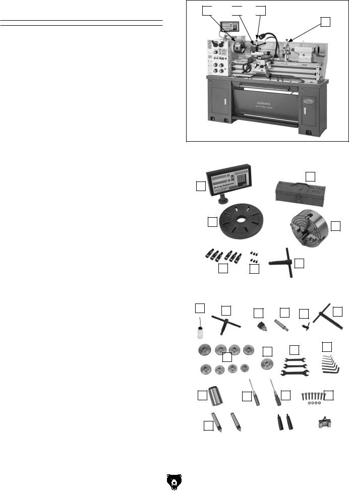
Inventory
The following is a list of items shipped with your machine. Before beginning setup, lay these items out and inventory them.
If any non-proprietary parts are missing (e.g. a nut or a washer), we will gladly replace them; or for the sake of expediency, replacements can be obtained at your local hardware store.
Mounted Inventory Components |
Qty |
|
A. |
Three-Jaw Universal Chuck 7"................... |
1 |
B. |
Quick-Change Tool Post w/Holder.............. |
1 |
C. |
Follow Rest................................................. |
1 |
D . Steady Rest................................................ |
1 |
|
Loose Inventory Components |
Qty |
|
E. |
DRO Unit..................................................... |
1 |
F. |
Toolbox........................................................ |
1 |
G. |
Faceplate 121⁄2"........................................... |
1 |
H. |
Four-Jaw Chuck 8"...................................... |
1 |
I. |
Camlock Studs (Installed)........................... |
6 |
J. |
Cap Screws M6-1 x 14 (Installed)............... |
6 |
K. |
Four-Jaw Chuck Wrench............................. |
1 |
Toolbox Inventory Components |
Qty |
|
L. |
Bottle for Oil................................................ |
1 |
M. |
Three-Jaw Chuck Key................................. |
1 |
N. |
Drill Chuck B16 1.6-13mm........................... |
1 |
O. |
Arbor B16 x MT#3....................................... |
1 |
P. |
Drill Chuck Key........................................... |
1 |
Q. |
Spindle Wrench........................................... |
1 |
R. |
End Gears 30T (Installed), 40T, 44T, 46T, |
|
|
52T, 54T, 56T, 57T, 63T ....................... |
1 Ea. |
S. |
End Gears 60T (One Installed)................... |
2 |
T.Open-End Wrench Set
|
10/12, 12/14, 17/19mm........................... |
1 Ea. |
U. |
Hex Wrenches 2, 2.5, 3, 4, 5, 6, 8mm..1 Ea. |
|
V. |
Tapered Spindle Sleeve MT#6 x MT#3....... |
1 |
W. |
Flat Head Screwdriver 3"............................ |
1 |
X. |
Phillips Screwdriver 3"................................ |
1 |
Y. |
Spider Screw w/Nuts................................... |
8 |
Z. |
Dead Center MT#3 Carbide Tip.................. |
1 |
AA. Dead Center MT#3 HSS Tip....................... |
1 |
|
AB. Handwheel Handles.................................... |
2 |
|
AC. Tool Holder (One Installed)......................... |
2 |
|
AD. End Gear 120/127T (Installed).................... |
1 |
|
Model G0824 (Mfd. Since 12/16)
A 
 B
B 
 C
C
D
Figure 9. Mounted inventory components.
|
|
|
|
|
|
|
|
|
|
|
|
|
|
|
|
|
|
|
|
|
|
|
|
|
|
|
|
|
|
|
|
|
|
|
|
|
|
|
|
|
|
|
|
|
|
|
|
|
|
|
|
|
|
|
|
|
|
|
|
|
|
|
|
|
|
|
|
|
|
|
|
|
|
|
|
|
|
|
|
|
|
F |
|
|
|
|
|
|
|
|
|
||
|
|
|
E |
|
|
|
|
|
|
|
|
|
|
|
|
|
|
|
|
|
|
|
|
|
|
|
|
|
|
|
|
|
|
|
|
|
|
|
|
|
|
|
|
|
||
|
|
|
|
|
|
|
|
|
|
|
|
|
|
|
|
|
|
|
|
|
|
|
|
|
|
|
|
|
|
|
|
|
|
|
|
|
|
|
|
|
|
|
|
|
|
|
|
|
|
|
|
|
|
|
G |
|
|
|
|
|
|
|
|
|
|
|
|
|
|
|
|
|
|
|
|
|
|
|
|
|
|
|
|
|
|
|
|
|
|
|
|||
|
|
|
|
|
|
|
|
|
|
|
|
|
|
|
|
|
|
|
|
|
|
|
|
|
|
|
|
|
|
H |
|
|
||||||||||||||
|
|
|
|
|
|
|
|
|
|
|
|
|
|
|
|
|
|
|
|
|
|
|
|
|
|
|
|
|
|
|
|
|
|
|
|
|
|
|
|
|
|
|
||||
|
|
|
|
|
|
|
|
|
|
|
|
|
|
|
|
|
|
|
|
|
|
|
|
|
|
|
|
|
|
|
|
|
|
|
|
|
|
|
|
|
|
|
|
|
||
|
|
|
|
|
|
|
|
|
|
|
|
|
|
|
|
|
|
|
|
|
|
|
|
|
|
|
|
|
|
|
K |
|
|
|
|
|
|
|
|
|
|
|
|
|
||
|
|
|
|
|
|
|
|
|
|
|
|
I |
|
|
|
|
|
J |
|
|
|
|
|
|
|
|
|
|
|
|
|
|
|
|
|
|
|
|
|
|
|
|||||
|
|
|
|
|
|
|
|
|
|
|
|
|
|
|
|
|
|
|
|
|
|
|
|
|
|
|
|
|
|
|
|
|
|
|
|
|
|
|
|
|||||||
|
|
|
|
|
|
|
|
|
|
|
|
|
|
|
|
|
|
|
|
|
|
|
|
|
|
|
|
|
|
|
|
|
|
|
|
|
|
|
|
|
|
|
|
|
|
|
|
|
|
Figure 10. Loose inventory components. |
|||||||||||||||||||||||||||||||||||||||||||
|
|
|
|
|
|
|
|
|
|
|
|
|
|
|
|
|
|
|
|
|
|
|
|
|
|
|
|
|
|
|
|
|
|
|
|
|
|
|
|
|
|
|
|
|
|
|
|
|
|
L |
|
|
|
|
|
|
|
|
|
|
|
|
|
|
|
|
|
|
|
|
|
|
|
|
|
|
|
|
|
|
|
|
|
|
|
|
|
|
|
|
|
|
|
|
|
|
|
|
|
|
|
|
|
|
M |
|
|
|
|
|
|
|
|
|
|
|
|
|
|
|
|
|
|
|
|
|
|
|
|
|
|
|
|
|
|
|
|
|||
|
|
|
|
|
|
|
|
|
|
|
|
|
|
|
|
|
|
|
|
|
|
|
|
|
|
|
|
|
|
|
|
|
|
|
|
|
|
|
|
Q |
|
|||||
|
|
|
|
|
|
|
|
|
|
|
|
|
|
|
|
N |
|
|
O |
|
|
|
|
|
|
|
|
|
|
|
|
|
|
|
|
|
|
|||||||||
|
|
|
|
|
|
|
|
|
|
|
|
|
|
|
|
|
|
|
|
|
|
|
P |
|
|
|
|
|
|
|
|
|
|
|||||||||||||
|
|
|
|
|
|
|
|
|
|
|
|
|
|
|
|
|
|
|
|
|
|
|
|
|
|
|
|
|
|
|||||||||||||||||
|
|
|
|
|
|
|
|
|
|
|
|
|
|
|
|
|
|
|
|
|
|
|
|
|
|
|
|
|
|
|
|
|
||||||||||||||
|
|
|
|
|
|
|
|
|
|
|
|
|
|
|
|
|
|
|
|
|
|
|
|
|
|
|
|
|
|
|
|
|||||||||||||||
|
|
|
|
|
|
|
|
|
|
|
|
|
|
|
|
|
|
|
|
|
|
|
|
|
|
|
|
|
|
|
|
|
|
|
|
|
|
|
|
|
|
|
|
|||
|
|
|
|
|
|
|
|
|
|
|
|
|
|
|
|
|
|
|
|
|
|
|
|
|
|
|
|
|
|
|
|
|
|
|
|
|
|
|
|
|
|
|
|
|
|
|
|
|
|
|
|
|
|
|
|
|
|
|
|
|
|
|
|
|
|
|
|
|
|
|
|
|
|
|
|
|
|
|
|
|
|
|
|
|
|
|
|
|
|
|
|
|
|
|
|
|
|
|
|
|
|
|
|
|
|
|
|
|
|
|
|
|
|
|
|
|
|
|
|
|
|
|
|
|
|
|
|
|
|
|
|
|
|
|
|
|
|
|
|
|
|
|
|
|
|
|
|
|
|
|
|
|
|
|
|
|
|
|
|
|
|
|
|
|
|
|
|
|
|
|
|
|
|
|
|
|
|
|
U |
|
|
|
|
|
|||
|
|
|
|
|
|
|
|
|
|
|
|
|
|
|
|
|
|
|
|
|
|
|
|
|
|
|
|
|
T |
|
|
|
|
|||||||||||||
|
|
|
|
|
|
|
|
|
|
|
|
|
|
|
|
|
|
|
|
|
|
|
|
S |
|
|
|
|
|
|
|
|
|
|
|
|
|
|
|
|
||||||
|
|
|
|
|
|
|
|
|
|
|
|
|
|
|
|
|
|
|
|
|
|
|
|
|
|
|
|
|
|
|
|
|
|
|
|
|
|
|
|
|
|
|
||||
|
|
|
|
|
|
|
|
|
|
|
|
|
R |
|
|
|
|
|
|
|
|
|
|
|
|
|
|
|
|
|
|
|
|
|
|
|
|
|
|
|||||||
|
|
|
|
|
|
|
|
|
|
|
|
|
|
|
|
|
|
|
|
|
|
|
|
|
|
|
|
|
|
|
|
|
|
|
|
|||||||||||
|
|
|
|
|
|
|
|
|
|
|
|
|
|
|
|
|
|
|
|
|
|
|
|
|
|
|
|
|
|
|
|
|
|
|
|
|
|
|
|
|
|
|
|
|||
|
|
|
|
|
|
|
|
|
|
|
|
|
|
|
|
|
|
|
|
|
|
|
|
|
|
|
|
|
|
|
|
|
|
|
|
|
|
|
|
|
|
|
|
|
|
|
|
|
|
V |
|
|
|
|
|
|
|
|
|
|
|
|
|
|
|
|
|
|
X |
|
|
|
|
|
|
|
Y |
|
|
|
|||||||||||||
|
|
|
|
|
|
|
|
|
|
|
|
|
W |
|
|
|
|
|
|
|
|
|
|
|
|
|
|
|
|
|
|
|
|
|||||||||||||
|
|
|
|
|
|
|
|
|
|
|
|
|
|
|
|
|
|
|
|
|
|
|
|
|
|
|
|
|
|
|
|
|
|
|
|
|
|
|
|
|
|
|||||
|
|
|
|
|
|
|
|
|
|
|
|
|
|
|
|
|
|
|
|
|
|
|
|
|
|
|
|
|
|
|
|
|
|
|
|
|
|
|
||||||||
|
|
|
|
|
|
Z |
|
|
|
|
|
|
|
|
AA |
|
|
|
|
|
|
|
|
|
|
|
|
|
|
|
|
|
|
|
|
|
|
|
|
|
|
|||||
|
|
|
|
|
|
|
|
|
|
|
|
|
|
|
|
|
|
|
|
|
|
|
|
|
|
AB |
|
|
|
|
|
|
|
AC |
|
|
||||||||||
|
|
|
|
|
|
|
|
|
|
|
|
|
|
|
|
|
|
|
|
|
|
|
|
|
|
|
|
|
|
|
|
|
|
|
|
|
|
|
|
|
|
|
|
|
|
|
|
|
|
|
|
|
|
|
|
|
|
|
|
|
|
|
|
|
|
|
|
|
|
|
|
|
|
|
|
|
|
|
|
|
|
|
|
|
|
|
|
|
|
|
|
|
|
Figure 11. Toolbox inventory.
-17-

Cleanup
The unpainted surfaces of your machine are coated with a heavy-duty rust preventative that prevents corrosion during shipment and storage. This rust preventative works extremely well, but it will take a little time to clean.
Be patient and do a thorough job cleaning your machine. The time you spend doing this now will give you a better appreciation for the proper care of your machine's unpainted surfaces.
There are many ways to remove this rust preventative, but the following steps work well in a wide variety of situations. Always follow the manufacturer’s instructions with any cleaning product you use and make sure you work in a well-ventilated area to minimize exposure to toxic fumes.
Before cleaning, gather the following:
•Disposable rags
•Cleaner/degreaser (WD•40 works well)
•Safety glasses & disposable gloves
•Plastic paint scraper (optional)
Basic steps for removing rust preventative:
1.Put on safety glasses.
2.Coat the rust preventative with a liberal amount of cleaner/degreaser, then let it soak for 5–10 minutes.
3.Wipe off the surfaces. If your cleaner/degreaser is effective, the rust preventative will wipe off easily. If you have a plastic paint scraper, scrape off as much as you can first, then wipe off the rest with the rag.
4.Repeat Steps 2–3 as necessary until clean, then coat all unpainted surfaces with a quality metal protectant to prevent rust.
-18-
Gasoline and petroleum products have low flash points and can explode or cause fire if used to clean machinery. Avoid using these products to clean machinery.
Many cleaning solvents are toxic if inhaled. Only work in a well-ventilated area.
NOTICE
Avoid chlorine-based solvents, such as acetone or brake parts cleaner, that may damage painted surfaces.
T23692—Orange Power Degreaser
A great product for removing the waxy shipping grease from the non-painted parts of the machine during clean up.
Figure 12. T23692 Orange Power Degreaser.
Model G0824 (Mfd. Since 12/16)
Site Considerations
Weight Load
Refer to the Machine Data Sheet for the weight of your machine. Make sure that the surface upon which the machine is placed will bear the weight of the machine, additional equipment that may be installed on the machine, and the heaviest workpiece that will be used. Additionally, consider the weight of the operator and any dynamic loading that may occur when operating the machine.
Space Allocation
Consider the largest size of workpiece that will be processed through this machine and provide enough space around the machine for adequate operator material handling or the installation of auxiliary equipment. With permanent installations, leave enough space around the machine to open or remove doors/covers as required by the maintenance and service described in this manual.
See below for required space allocation.
Children or untrained people may be seriously injured by this machine. Only install in an access restricted location.
Physical Environment
The physical environment where the machine is operated is important for safe operation and longevity of machine components. For best results, operate this machine in a dry environment that is free from excessive moisture, hazardous chemicals, airborne abrasives, or extreme conditions. Extreme conditions for this type of machinery are generally those where the ambient temperature range exceeds 41°–104°F; the relative humidity range exceeds 20%–95% (non-condensing); or the environment is subject to vibration, shocks, or bumps.
Electrical Installation
Place this machine near an existing power source. Make sure all power cords are protected from traffic, material handling, moisture, chemicals, or other hazards. Make sure to leave enough space around machine to disconnect power supply or apply a lockout/tagout device, if required.
Lighting
Lighting around the machine must be adequate enough that operations can be performed safely. Shadows, glare, or strobe effects that may distract or impede the operator must be eliminated.
|
|
Wall |
|
|
96" |
|
|
30" |
|
Electrical Box |
Minimum |
|
|
|
|
Access Cover |
|
Keep |
|
Lathe |
|
|
|
Workpiece |
|
32" |
Loading Area |
|
|
|
|
|
Unobstructed |
|
|
24"
Minimum
Figure 13. Minimum working clearances.
Model G0824 (Mfd. Since 12/16) |
-19- |
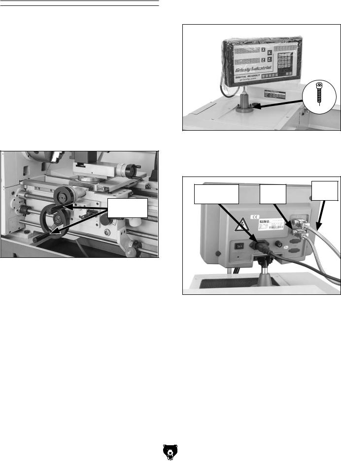
Assembly
The machine must be fully assembled before it can be operated. Before beginning the assembly process, refer to Needed for Setup and gather all listed items. To ensure the assembly process goes smoothly, first clean any parts that are covered or coated in heavy-duty rust preventative (if applicable).
With the exception of the handwheels and DRO unit, the Model G0824 is shipped fully assembled.
To assemble lathe:
1.Thread handles into handwheels, as shown in Figure 14.
Handwheel
Handles
Figure 14. Handwheel handles installed.
2. Secure DRO assembly to threaded mounting holes in headstock cover, using (3) pre-installed M8-1.25 x 20 cap screws (see Figure 15).
x 3
Figure 15. DRO unit mounted to headstock.
3. Connect X- and Z-axis cables and power cord to back of DRO unit, as shown in Figure 16.
DRO Power |
Z-Axis |
X-Axis |
|
Cable |
|||
Cord |
Cable |
||
|
Figure 16. DRO electrical connections.
-20- |
Model G0824 (Mfd. Since 12/16) |
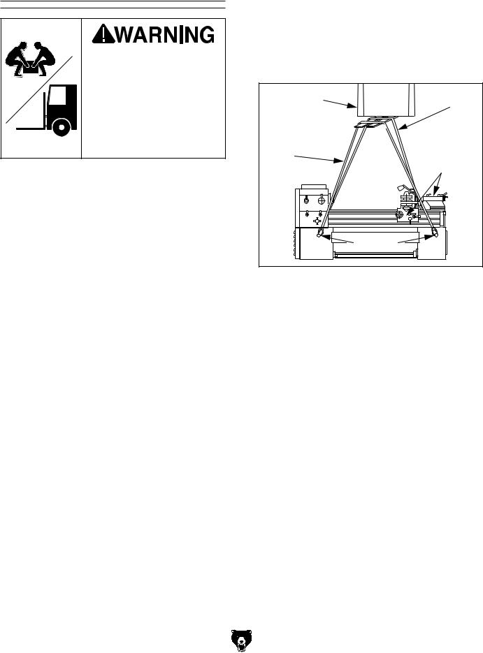
Lifting & Placing
HEAVY LIFT! Straining or crushing injury may occur from improperly lifting machine or some of its parts. To reduce this risk, get help from other people and use a forklift (or other lifting equipment) rated for weight of this machine.
Do not attempt to lift or move this lathe without using the proper lifting equipment (such as forklift or crane) or the necessary assistance from other people. Each piece of lifting equipment must be rated for at least 2000 lbs. to support dynamic loads that may be applied while lifting. Refer to
Needed for Setup on Page 16 for details.
To lift and move lathe:
1.Remove shipping crate top and sides, then remove small components from shipping pallet.
2.Move lathe to its prepared location while it is still attached to shipping pallet.
3.Unbolt lathe from shipping pallet.
4.To balance load for lifting, move tailstock and carriage to extreme right end of bedway, then lock them in place.
Note: Before attempting to move the carriage, make sure the carriage lock is loose, the half nut is disengaged, and the power feed is disengaged, using the feed selection lever (see Page 4 for reference).
5.Remove back splash so it does not get damaged when lathe is raised.
Model G0824 (Mfd. Since 12/16)
6.Insert round steel bar stock through four lifting holes (see Figure 17).
Note: To properly support the lathe and avoid damaging lathe components, bar stock should be at least 11⁄4" diameter thick and 44" long, so it projects 14" from both sides of the lathe when installed.
Power Lifting |
Rear |
Equipment |
Lifting |
|
Strap |
Front |
Carriage & |
Lifting |
Tailstock |
Strap |
to Right |
Bar Stock |
Figure 17. Example of lathe setup for lifting.
7.Attach lifting straps to bar stock and powerlifting equipment (see Figure 17). Make sure there is enough space between straps and control rod, feed rod, leadscrew and electrical cabinet to prevent putting pressure on these components when lifting.
8.Raise lathe a couple of inches and check balance of load. Have two other people carefully steady lathe to help prevent it from swinging.
—If load is not safely balanced, immediately lower lathe and resolve issue before attempting to lift it again.
9.Raise lathe enough to clear shipping pallet and carefully remove pallet.
10.Lower lathe into position.
11.Re-install back splash.
-21-
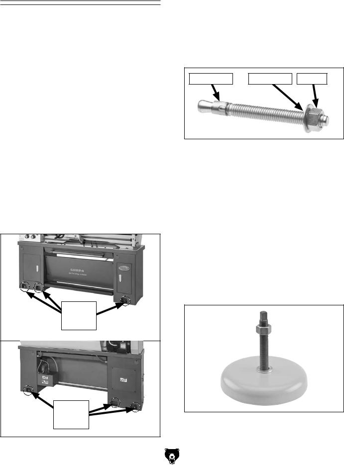
Anchoring to Floor
Number of Mounting Holes............................. |
6 |
Diameter of Mounting Hardware................. |
1⁄2" |
Anchoring machinery to the floor prevents tipping or shifting and reduces vibration that may occur during operation, resulting in a machine that runs slightly quieter and feels more solid.
If the machine will be installed in a commercial or workplace setting, or if it is permanently connected (hardwired) to the power supply, local codes may require that it be anchored to the floor.
If not required by any local codes, fastening the machine to the floor is an optional step. If you choose not to do this with your machine, we recommend placing it on machine mounts, as these provide an easy method for leveling and they have vibration-absorbing pads.
Anchoring to Concrete Floors
1. Use holes in bottom of cabinets (see Figure 18) as guides for drilling holes in floor and mount stand.
Front
Mounting
Holes
Rear
Mounting
Holes
Figure 18. Locations for mounting lathe.
-22-
2.Follow Steps 4–8 in Lifting & Placing on
Page 21, raise lathe up as needed and install anchor studs (see Figure 19) in concrete floor.
3.Lower lathe into position so anchor studs slide into holes in cabinets, then secure anchor studs with hex nuts and flat washers (see Figure 19).
Anchor Stud |
Flat Washer |
Hex Nut |
Figure 19. Typical anchor stud.
4.Shim between lathe and chip pan as necessary to level the ways at all four corner locations (refer to Leveling on Page 23).
5.For best results, recheck ways in 24 hours to make sure they are still level and have not twisted. Re-shim as required.
Using Machine Mounts
G7160—Machine Mount 43⁄4" 8,000 lb. Capacity
For the ultimate in heavy machine stabilization, these mounts feature easy setting, fast leveling, and vibration and noise reduction. Large rubber foot pads distribute weight evenly and long mounting studs provide a wide range of leveling adjustment. Sold individually. Stud size: M12-1.75 x 72.
Figure 20. G7160 Machine Mount.
Model G0824 (Mfd. Since 12/16)

Leveling |
Lubricating Lathe |
|
|
|
|
|
|
|
For accurate turning results and to prevent warping or twisting of cast iron bed and ways, lathe bedways MUST be leveled from side to side and from front to back on both ends.
Re-check the bedways 24 hours after installation, two weeks after that, and then annually to make sure they remain level.
Leveling machinery helps precision components, such as bedways, remain straight and flat during the lifespan of the machine. Components on a machine that is not level may slowly twist due to the dynamic loads placed on the machine during operation.
If needed, use metal shims between the lathe bed and chip pan when leveling the machine.
For best results, use a precision level that is at least 12" long and sensitive enough to show a distinct movement when a 0.003" shim (approximately the thickness of one sheet of standard newspaper) is placed under one end of the level.
See the figure below for an example of a high precision level offered by Grizzly.
GEARBOXES MUST
BE FILLED WITH OIL!
LATHE MAY NOT HAVE OIL INCLUDED!
Refer to the Lubrication Section in this Manual for Recommended Oil Type.
The headstock, quick-change gearbox, and apron oil reservoirs must have the proper amount of oil in them before the lathe can be operated.
Damage caused to the bearings and gears from running the lathe without oil in the reservoirs will not be covered under warranty. Refer to the Lubrication section, beginning on Page 64, for checking and adding oil.
In addition to the reservoirs, we also recommend that you lubricate all other points on the machine at this time. To do this, follow the steps provided in the maintenance schedule on Page 63.
Note: If this lathe was shipped with oil in the reservoirs, do not change that oil until after the test run and spindle break-in procedures.
Figure 21. Model H2683 Master Machinist's
Level.
Model G0824 (Mfd. Since 12/16)
Adding Coolant
Add the coolant of your choice now. For detailed instructions on where the coolant tank is located and how to add fluid, refer to Coolant System Service on Page 69.
-23-
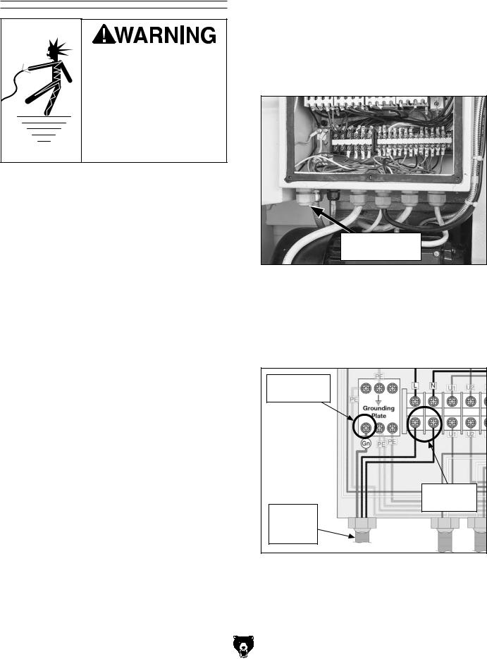
Power Connection
Electrocution or fire may occur if machine is ungrounded, incorrectly connected to power, or connected to an undersized circuit. Use an electrician or a qualified service personnel to ensure a safe power connection.
Before the machine can be connected to the power supply, there must be an electrical circuit that meets the Circuit Requirements for 220V on Page 14.
To minimize the risk of electrocution, fire, or equipment damage, installation work and electrical wiring MUST be done by an electrician or qualified service personnel.
Note About Extension Cords: Using an incorrectly sized extension cord may decrease the life of electrical components on your machine. Refer to Extension Cords on Page 15 for more information.
-24-
To connect the power cord to the lathe:
1.Press Emergency Stop/RESET button on front of headstock, remove six Phillips head screws that secure electrical box cover, then remove cover.
2.Thread power cord through strain relief shown in Figure 22.
Incoming Power
Strain Relief
Figure 22. Location of hot wire terminals, ground terminal, and strain relief.
3.Identify L and N terminals and grounding plate (PE), shown in Figure 23, then connect incoming hot wires and ground wire to those terminals.
Ground Wire
Connected
Hot Wires
Connected
Incoming
Power
Cord
Figure 23. Incoming ground and hot wires connected.
Model G0824 (Mfd. Since 12/16)

4.Make sure wires have enough slack between strain relief and terminal connections so they are not pulled tight or stretched, then tighten strain relief to secure cord.
Note: The strain relief must be tightened against the outer jacket of the cord. Avoid over-tightening the strain relief or it may crush the cord and cause a short.
5.Test the strain relief to ensure it is properly tightened by pulling the cord from outside the box with light-to-moderate force. When strain relief is properly tightened, cord will not move inside cabinet.
6.Install a NEMA 6-15 plug on the other end of the power cord per plug manufacturer's instructions.
7.Re-install main electrical box cover.
To avoid unexpected start-up, keep the RESET button pressed in until instructed otherwise in the Test Run.
8.Plug cord into matching power supply receptacle and power source as specified in Circuit Requirements for 220V on Page 14.
Model G0824 (Mfd. Since 12/16)
Test Run
Once assembly is complete, test run the machine to ensure it is properly connected to power and safety components are functioning correctly.
If you find an unusual problem during the test run, immediately stop the machine, disconnect it from power, and fix the problem BEFORE operating the machine again. The Troubleshooting table in the SERVICE section of this manual can help.
Serious injury or death can result from using this machine BEFORE understanding its controls and related safety information. DO NOT operate, or allow others to operate, machine until the information is understood.
DO NOT start machine until all preceding setup instructions have been performed. Operating an improperly set up machine may result in malfunction or unexpected results that can lead to serious injury, death, or machine/property damage.
The test run consists of verifying the following:
•Motor powers up and runs correctly
•Emergency Stop/RESET button works correctly.
•Brake system works correctly
•Lamp works correctly
•Coolant system works correctly
•Jog button works correctly
To test run machine:
1. Clear away all tools and objects used during assembly, lubrication, and preparation.
2. Secure chuck and jaws, if installed (refer to
Chuck Installation on Page 30).
Note: If a chuck is not installed on the lathe, you do not need to install one for this test.
-25-
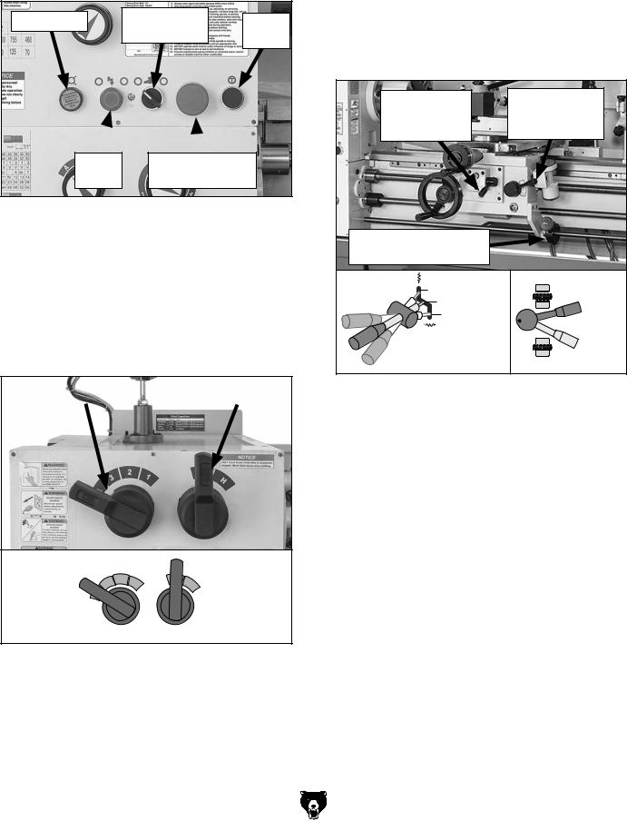
3.Push Emergency Stop/RESET button on control panel (see Figure 24), and point coolant nozzle into chip pan.
Power Light |
Coolant |
|
Jog |
|
Pump Switch |
Button |
|
|
|
||
Power |
Emergency Stop/ |
|
|
Button |
RESET Button |
|
|
Figure 24. Control panel buttons used in test run.
Note: In the next step, you may need to rock the chuck back and forth as you make the adjustments to cause the gears to mesh.
4.Move spindle speed and speed range levers to L and 4. This will set spindle rotation at 70 RPM (see Figure 25).
Speed Lever |
|
Speed Range |
|
|
|
Speed |
Speed |
Range |
|
Lever |
Lever |
Set to "4" |
Set to "L" |
Figure 25. Spindle speed set to 70 RPM.
5.Make sure spindle lever is in OFF (middle) position (see Figure 26) to prevent unexpected startup when power is enabled.
Note: You need to pull the lever out (or right) to disengage the lug in order to adjust the position.
-26-
6.To ensure carriage components do not unexpectedly move during the following steps, disengage half nut lever and feed selection lever (see Figure 26). Rotate carriage and cross slide handwheels back and forth while moving levers to verify they are disengaged. When disengaged, handwheels will turn with ease.
Feed Lever is |
Half Nut Lever |
|
Horizontal |
is Pulled Up |
|
(Disengaged) |
(Disengaged) |
|
Spindle Lever |
|
|
(OFF, Center Position) |
|
|
Cross Slide |
Disengaged |
|
Disengaged |
|
|
Carriage |
Half Nut |
|
|
||
Feed Selection |
Lever |
|
Engaged |
||
Lever |
||
|
Figure 26. Disengaging carriage components.
7.Rotate Emergency Stop/RESET button clockwise so it pops out. Power light on the control panel should illuminate.
8.Push power button, then move spindle lever (see Figure 26) down to start spindle. The top of the chuck should turn down and toward front of lathe.
—When operating correctly, machine will run smoothly with little or no vibration or rubbing noises.
—Investigate and correct strange or unusual noises or vibrations before operating machine further. Always disconnect machine from power when investigating or correcting potential problems.
Model G0824 (Mfd. Since 12/16)

9.Push Emergency Stop/RESET button to turn lathe OFF, then, without resetting RESET button, try to restart spindle rotation, as instructed in Step 8. Spindle should not start.
—If spindle rotation does start with Emergency Stop/RESET button pressed in, the Emergency Stop/RESET button safety is not operating correctly. This safety feature must operate properly before continuing operation. Use spindle lever to stop lathe, disconnect it from power, and call Tech Support for help.
10.Move spindle lever to OFF (middle) position, and reset Emergency Stop/RESET button by twisting it clockwise until it pops out.
11.Restart spindle rotation.
12.Step on foot brake. Spindle should come to a quick stop.
—If brake pedal has no effect on lathe, push Emergency Stop/RESET button and call Tech Support for help.
13.Ensure work lamp functions properly.
14.Use cutting fluid pump switch on control panel to start pump (see Figure 24 on Page 26), then open valve. Verify that cutting fluid flows from nozzle, then turn pump OFF.
15.Press power button, then press and briefly hold the jog button (see Figure 24 on Page 26), then release it. The spindle should rotate when the jog button is pressed and come to a complete stop when released.
Congratulations! The test run is complete. Turn the lathe OFF and perform the following Spindle Break-In procedure.
Model G0824 (Mfd. Since 12/16)
Spindle Break-In
Before subjecting the spindle to operational loads, it is essential to complete the break-in process. This helps maximize the life of spindle bearings and other precision components by thoroughly lubricating them before placing them under load.
After spindle break-in is complete, we recommend changing headstock and gearbox oil to remove any metal particles or debris that are present from the assembly and break-in process.
The break-in must be performed in succession with the Test Run procedure described in this manual, as the steps in that procedure prepare the lathe controls for the break-in process.
DO NOT perform this procedure independently of the Test Run section. The lathe could be seriously damaged if the controls are set differently than instructed in that section.
To perform the spindle break-in:
1.Successfully complete the Test Run procedure beginning on Page 25.
2.Run spindle at 70 RPM for 10 minutes in each direction (first forward and then reverse).
3.Turn lathe OFF. Set spindle speed levers for 125 RPM (see Setting Spindle Speed on
Page 48 for more information), then run lathe for 5 minutes in each direction.
4.Repeat Step 3 for remaining spindle speeds, progressively increasing to highest speed listed on spindle speed chart.
5.Press Emergency Stop/RESET button and DISCONNECT MACHINE FROM POWER!
Congratulations! The spindle break-in is complete. We recommend changing the headstock and gearbox oil before operating the machine further (refer to Lubrication on Page 64).
-27-

SECTION 4: OPERATIONS
Operation Overview
The purpose of this overview is to provide the novice machine operator with a basic understanding of how the machine is used during operation, so the machine controls/components discussed later in this manual are easier to understand.
Due to the generic nature of this overview, it is not intended to be an instructional guide. To learn more about specific operations, read this entire manual, seek additional training from experienced machine operators, and do additional research outside of this manual by reading "how-to" books, trade magazines, or websites.
To reduce your risk of serious injury, read this entire manual BEFORE using machine.
To reduce risk of eye or face injury from flying chips, always wear approved safety glasses and face shield when operating this machine.
If you are not experienced with this type of machine, WE STRONGLY RECOMMEND that you seek additional training outside of this manual. Read books/magazines or get formal training before beginning any projects. Regardless of the content in this section, Grizzly Industrial will not be held liable for accidents caused by lack of training.
To complete a typical operation, the operator does the following:
1.Securely mounts workpiece in lathe.
2.Puts on safety glasses and a face shield, rolls up sleeves, removes jewelry, and secures any clothing, jewelry, or hair that could get entangled in moving parts.
3.Installs tooling, aligns it with workpiece, then backs it away to establish a safe startup clearance.
4.Removes all setup tools from lathe.
5.Checks for safe clearances by rotating workpiece by hand at least one full revolution.
6.Sets correct spindle speed for operation.
7.If using power feed, selects proper feed rate for operation.
8.Resets Emergency Stop/RESET button.
9.Uses spindle lever to start spindle rotation.
10.Uses carriage handwheels or power feed options to move tooling into workpiece for operations.
11.When finished cutting, moves spindle lever to OFF position, presses foot pedal brake to completely stop spindle, presses Emergency Stop/RESET button, and then removes workpiece.
-28- |
Model G0824 (Mfd. Since 12/16) |
Loading...