


14'' BANDSAW
MODEL G1019
INSTRUCTION MANUAL
COPYRIGHT © 1991 BY GRIZZLY INDUSTRIAL, INC.. REG.# TX 3 360 514 WARNING: NO PORTION OF THIS MANUAL MAY BE REPRODUCED IN ANY SHAPE OR FORM WITHOUT THE WRITTEN APPROVAL OF GRIZZLY INDUSTRIAL, INC. REVISED JULY, 2001. PRINTED IN TAIWAN

WARNING
Some dust created by power sanding, sawing, grinding, drilling, and other construction activities contains chemicals known to the State of California to cause cancer, birth defects or other reproductive harm. Some examples of these chemicals are:
•Lead from lead-based paints.
•Crystalline silica from bricks, cement, and other masonry products.
•Arsenic and chromium from chemically treated lumber.
Your risk from these exposures varies, depending on how often you do this type of work. To reduce your exposure to these chemicals: work in a well ventilated area, and work with approved safety equipment, such as those dust masks that are specially designed to filter out microscopic particles.

Table Of Contents
PAGE
1.SAFETY
|
SAFETY RULES FOR ALL TOOLS.................................................................. |
2-3 |
|
ADDITIONAL SAFETY INSTRUCTIONS FOR BANDSAWS .............................. |
4 |
2. |
CIRCUIT REQUIREMENTS ...................................................................................... |
5 |
|
110V OPERATION .............................................................................................. |
5 |
|
220V OPERATION .............................................................................................. |
5 |
|
EXTENSION CORDS .......................................................................................... |
6 |
|
GROUNDING ...................................................................................................... |
6 |
3. |
GENERAL INFORMATION ...................................................................................... |
7 |
|
UNPACKING ........................................................................................................ |
8 |
|
PIECE INVENTORY ............................................................................................ |
8 |
|
CLEAN UP............................................................................................................ |
9 |
|
SITE CONSIDERATIONS .................................................................................... |
9 |
4. |
ASSEMBLY ............................................................................................................ |
10 |
|
STAND .......................................................................................................... |
10-12 |
|
SWITCH ............................................................................................................ |
13 |
|
BANDSAW TO STAND ...................................................................................... |
14 |
|
V-BELT .............................................................................................................. |
14 |
|
STAND GUARDS .............................................................................................. |
15 |
|
TABLE ................................................................................................................ |
16 |
|
DUST PORT ...................................................................................................... |
17 |
|
FENCE .......................................................................................................... |
17-18 |
|
BLADES ............................................................................................................ |
18 |
5. |
ADJUSTMENTS ...................................................................................................... |
19 |
|
LOCATION OF CONTROLS ........................................................................ |
19-20 |
|
BLADE TENSION .............................................................................................. |
20 |
|
BLADE TRACKING ............................................................................................ |
21 |
|
BLADE GUIDES............................................................................................ |
21-22 |
|
TABLE ADJUSTMENTS .............................................................................. |
22-24 |
|
FENCE ADJUSTMENTS.................................................................................... |
24 |
|
BLADE LEAD .................................................................................................... |
25 |
|
TEST RUN.......................................................................................................... |
25 |
6. |
OPERATIONS.......................................................................................................... |
26 |
|
BLADE INFORMATION...................................................................................... |
27 |
|
CHANGING BLADES.................................................................................... |
27-28 |
|
RIPPING ............................................................................................................ |
28 |
|
STACKED CUTS................................................................................................ |
29 |
|
CUTTING CURVES............................................................................................ |
29 |
|
CIRCLE CUTTING ATTACHMENT.................................................................... |
30 |
|
RESAWING ........................................................................................................ |
31 |
7. |
MAINTENANCE ...................................................................................................... |
32 |
|
GENERAL .......................................................................................................... |
32 |
|
TABLE ................................................................................................................ |
32 |
|
BEARINGS ........................................................................................................ |
32 |
|
V-BELT .............................................................................................................. |
32 |
8. |
CLOSURE................................................................................................................ |
33 |
|
WIRING DIAGRAM ............................................................................................ |
34 |
|
MACHINE DATA ................................................................................................ |
35 |
|
TROUBLESHOOTING ...................................................................................... |
36 |
|
PART BREAKDOWN .................................................................................... |
37-39 |
|
PART LISTS.................................................................................................. |
40-41 |
|
WARRANTY AND RETURNS............................................................................ |
42 |
G1019 14'' Bandsaw |
-1- |
SECTION 1: SAFETY
For Your Own Safety Read Instruction Manual Before Operating This Equipment
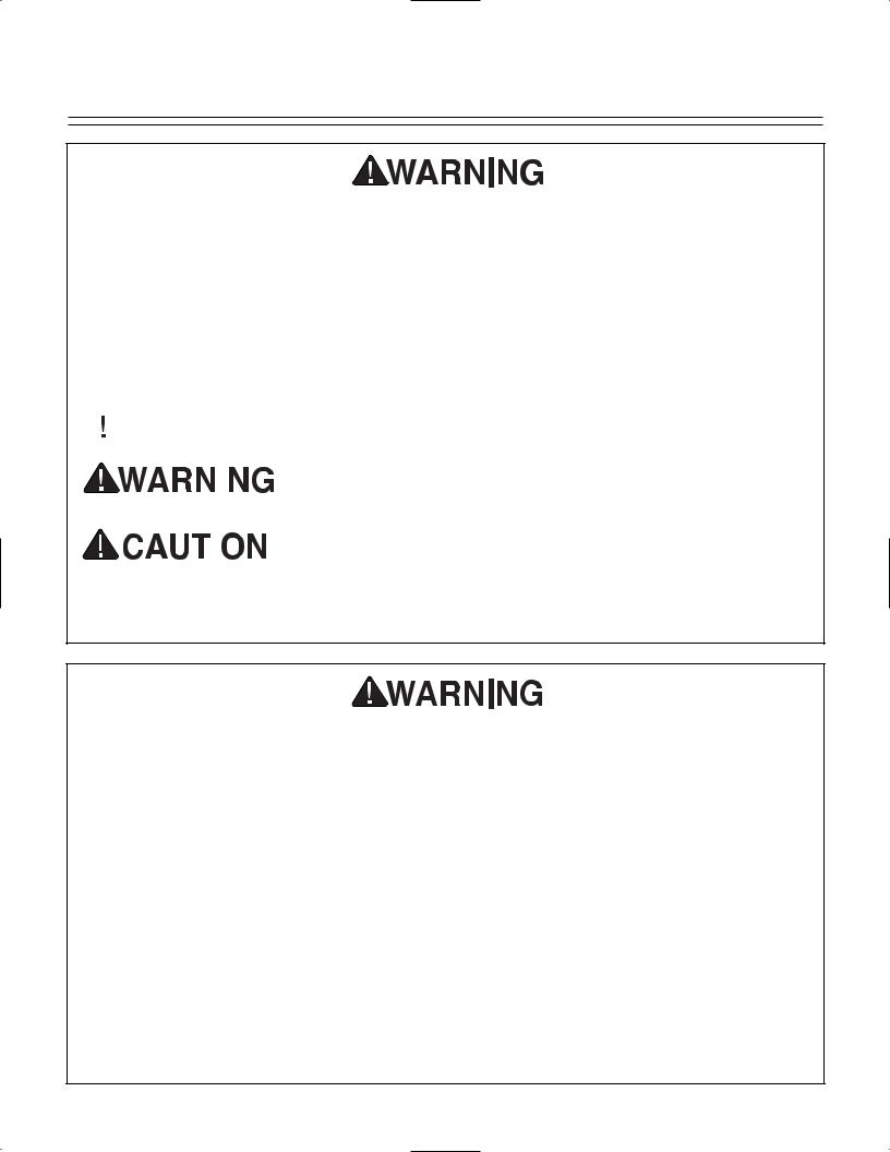
The purpose of safety symbols is to attract your attention to possible hazardous conditions. This manual uses a series of symbols and signal words which are intended to convey the level of importance of the safety messages. The progression of symbols is described below. Remember that safety messages by themselves do not eliminate danger and are not a substitute for proper accident prevention measures.
|
|
|
|
|
Indicates an imminently hazardous situation which, if not |
|
|
|
|
|
avoided, WILL result in death or serious injury. |
|
|
|
|
|
Indicates a potentially hazardous situation which, if not |
|
|
|
|
|
|
|
|
|
|
|
avoided, COULD result in death or serious injury. |
|
|
|
|
|
|
|
|
|
|
|
Indicates a potentially hazardous situation which, if not |
|
|
|
|
|
avoided, MAY result in minor or moderate injury. It may also |
|
|
|
|
|
|
|
|
|
|
|
be used to alert against unsafe practices. |
|
|
|
|
|
|
NOTICE |
This symbol is used to alert the user to useful information |
||||
about proper operation of the equipment. |
|||||
Safety Instructions For Power Tools
1.KEEP GUARDS IN PLACE and in working order.
2.REMOVE ADJUSTING KEYS AND WRENCHES. Form habit of checking to see that keys and adjusting wrenches are removed from tool before turning on.
3.KEEP WORK AREA CLEAN. Cluttered areas and benches invite accidents.
4.NEVER USE IN DANGEROUS ENVIRONMENT. Don’t use power tools in damp or wet locations, or where any flammable or noxious fumes may exist. Keep work area well lighted.
5.KEEP CHILDREN AND VISITORS AWAY. All children and visitors should be kept a safe distance from work area.
6.MAKE WORKSHOP CHILD PROOF with padlocks, master switches, or by removing starter keys.
7.NEVER FORCE TOOL. It will do the job better and safer at the rate for which it was designed.
8.USE RIGHT TOOL. Don’t force tool or attachment to do a job for which it was not designed.
-2- |
G1019 14'' Bandsaw |

Safety Instructions For Power Tools
9.USE PROPER EXTENSION CORD. Make sure your extension cord is in good condition. Conductor size should be in accordance with the chart below. The amperage rating should be listed on the motor or tool nameplate. An undersized cord will cause a drop in line voltage resulting in loss of power and overheating. Your extension cord must also contain a ground wire and plug pin. Always repair or replace extension cords if they become damaged.
Minimum Gauge for Extension Cords
|
|
LENGTH |
|
|
AMP RATING |
25ft |
|
50ft |
100ft |
0-6 |
18 |
|
16 |
16 |
7-10 |
18 |
|
16 |
14 |
11-12 |
16 |
|
16 |
14 |
13-16 |
14 |
|
12 |
12 |
17-20 |
12 |
|
12 |
10 |
21-30 |
10 |
|
10 |
No |
|
|
|
|
|
10.WEAR PROPER APPAREL. Do not wear loose clothing, gloves, neckties, rings, bracelets, or other jewelry which may get caught in moving parts. Non-slip footwear is recommended. Wear protective hair covering to contain long hair.
11.ALWAYS USE SAFETY GLASSES. Also use face or dust mask if cutting operation is dusty. Everyday eyeglasses only have impact resistant lenses, they are NOT safety glasses.
12.SECURE WORK. Use clamps or a vise to hold work when practical. It’s safer than using your hand and frees both hands to operate tool.
13.NEVER OVERREACH. Keep proper footing and balance at all times.
14.MAINTAIN TOOLS WITH CARE. Keep tools sharp and clean for best and safest performance. Follow instructions for lubricating and changing accessories.
15.DISCONNECT TOOLS before servicing and changing accessories, such as blades, bits, cutters, and the like.
16.REDUCE THE RISK OF UNINTENTIONAL STARTING. Make sure switch is in off position before plugging in.
17.USE RECOMMENDED ACCESSORIES.
Consult the owner’s manual for recommended accessories. The use of improper accessories may cause risk of injury.
18.CHECK DAMAGED PARTS. Before further use of the tool, a guard or other part that is damaged should be carefully checked to determine that it will operate properly and perform its intended function. Check for alignment of moving parts, binding of moving parts, breakage of parts, mounting, and any other conditions that may affect its operation. A guard or other part that is damaged should be properly repaired or replaced.
19.NEVER LEAVE TOOL RUNNING UNATTENDED. TURN POWER OFF. Don’t leave tool until it comes to a complete stop.
20.DO NOT OPERATE WHILE UNDER THE INFLUENCE of drugs or alcohol, or while tired.
G1019 14'' Bandsaw |
-3- |
Additional Safety Instructions For Bandsaws
1.DO NOT OPERATE WITH DULL OR BADLY WORN BLADES. Dull blades require more effort to use and are difficult to control. Inspect blades before each use.
2.NEVER POSITION FINGERS OR THUMBS IN LINE WITH THE CUT.
Serious personal injury could occur.
3.DO NOT OPERATE THIS BANDSAW WITHOUT WHEEL, PULLEY, AND BLADE GUARDS IN PLACE.
4.WHEN REPLACING BLADES, make sure teeth face down toward the table. The force of the cut is always down. Make sure the blade is properly tensioned.
5.CUTS SHOULD ALWAYS BE FULLY SUPPORTED by the table or some type of support fixture. Always support round stock in a V-block.
6.DO NOT BACK WORKPIECE AWAY from the blade while the saw is running. Plan your cuts so you always cut out of the wood. if you need to back the work out, turn the bandsaw off and wait for the blade to come to a complete stop. Do not twist or put excessive stress on the blade while backing work away.
7.BLADE SHOULD BE RUNNING AT FULL SPEED before beginning a cut.
8.ALWAYS FEED STOCK EVENLY AND SMOOTHLY. Do not force or twist blade while cutting, especially when sawing small radii.
9.THIS MACHINE IS NOT DESIGNED TO CUT METAL or other material except wood.
10.DO NOT MANUALLY STOP OR SLOW BLADE after turning off the saw. Allow it to come to a complete stop before you leave it unattended.
11.ALL INSPECTIONS, ADJUSTMENTS, AND MAINTENANCE ARE TO BE DONE WITH THE POWER OFF and the plug pulled from the outlet. Wait for all moving parts to come to a complete stop.
12.HABITS – GOOD AND BAD – ARE HARD TO BREAK. Develop good habits in your shop and safety will become sec- ond-nature to you.
13.IF AT ANY TIME YOU ARE EXPERIENCING DIFFICULTIES PERFORMING THE INTENDED OPERATION, STOP USING THE MACHINE! Then contact our service department or ask a qualified expert how the operation should be performed.
Like all power tools, there is danger associated with bandsaws. Accidents are frequently caused by lack of familiarity or failure to pay attention. Use this tool with respect and caution to lessen the possibility of operator injury. If normal safety precautions are overlooked or ignored, serious personal injury may occur.
No list of safety guidelines can be complete. Every shop environment is different. Always consider safety first, as it applies to your individual working conditions. Use this and other machinery with caution and respect. Failure to do so could result in serious personal injury, damage to equipment or poor work results.
-4- |
G1019 14'' Bandsaw |
SECTION 2: CIRCUIT REQUIREMENTS
110V Operation |
220V Operation |
The motor supplied with the Model G1019 is a dual-voltage 110V or 220V motor prewired for 110V. Under 110V use, the motor draws approximately 12 amps. We recommend a 15 amp circuit breaker for 110V. This should be satisfactory for normal use, while providing enough protection against circuit damage caused by power surges. Grizzly recommends that the circuit you use should be dedicated, (i.e., the Model G1019 should provide the only draw from that circuit). If frequent circuit failures occur when using the bandsaw, contact our service department or your local electrical contractor.
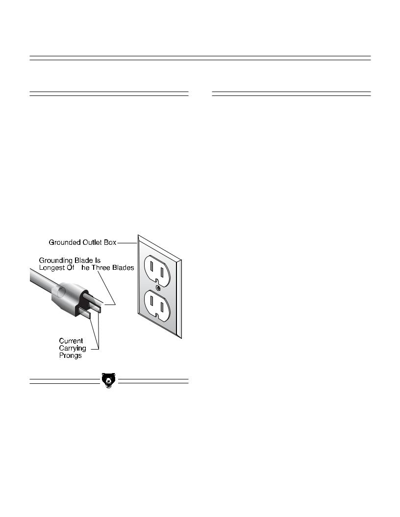
Figure 1. Typical 110V 3-prong plug and outlet.
The motor supplied with the Model G1019 can be rewired to operate at 220V. See enclosed wiring diagram for details.
If converting to operate at 220V, a suitable 220V plug must be wired in. When operating at 220V, we recommend using a NEMA-style 6L-15 plug and outlet. See Figure 2. You may also “hardwire” the machine directly to your panel, provided you place a disconnect switch near the machine. Check the electrical codes in your area for specifics on wiring requirements.
Under normal use, the motor draws approximately 6 amps at 220V. We recommend a 15 amp circuit breaker. This should be satisfactory for normal use while providing enough protection against circuit damage caused by power surges.
Figure 2. Recommended 220V receptacle.
G1019 14'' Bandsaw |
-5- |
Extension Cords |
Grounding |
Should it be necessary to use an extension cord, make sure the cord is rated Hard Service (grade S) or better. Refer to the chart on page 3 to determine the minimum gauge for the extension cord. The extension cord must also contain a ground wire and plug pin. Always repair or replace extension cords when they become worn or damaged.
We do not recommend the use of extension cords on 220V equipment. It is much better to arrange the placement of your equipment and the installed wiring to eliminate the need for extension cords.
We have covered some basic electrical requirements for the safe operation of your Bandsaw. These requirements are not necessarily comprehensive. You must be sure that your particular electrical configuration complies with local and state codes. Ensure compliance by checking with your local municipality or a licensed electrician.
In the event of an electrical short, grounding provides electric current a path of least resistance to reduce the risk of electric shock. This tool is equipped with an electric cord having an equip- ment-grounding conductor. The plug must be plugged into a matching outlet that is properly installed and grounded in accordance with all local codes and ordinances.
Improper connections of the electrical-grounding conductor can result in risk of electric shock. The conductor with green or green and yellow striped insulation is the electrical grounding conductor. If repair or replacement of the electric cord or plug is necessary, do not connect the equipment grounding conductor to a live terminal.
This equipment must be grounded. Verify that any existing electrical outlet and circuit you intend to plug into is actually grounded. Under no circumstances should the grounding pin from any three-pronged plug be removed. Serious injury may occur.
-6- |
G1019 14'' Bandsaw |

SECTION 3: GENERAL INFORMATION
Commentary
Grizzly Industrial, Inc. is proud to offer the Model G1019 14" Bandsaw. The Model G1019 is part of Grizzly’s growing family of fine woodworking and metalworking machinery. When used according to the guidelines stated in this manual, you can expect years of trouble-free, enjoyable operation.
The Model G1019 features cast iron construction for rigidity and strength, a solid cast iron table, a steel stand, fence and miter gauge and a 3⁄8" blade. The electrical package consists of a 3450 R.P.M., 3⁄4 H.P. capacitor start motor, locking toggle switch and cord set. Also included is a circle cutting guide to produce circular cuts up to 12" in diameter. Many accessories are also available for the Model G1019. Consult the current Grizzly catalog for prices and ordering information.
All running parts utilize shielded ball bearings that require no lubrication.
We are also pleased to provide this manual with the Model G1019. It was written to guide you through assembly, review safety considerations, and cover general operating procedures. It represents our effort to produce the best documentation possible. If you have any comments regarding this manual, please write to us at the address below:
Grizzly Industrial, Inc.
C/O Technical Documentation
P.O. Box 2069
Bellingham, WA 98227-2069
Above all else, we stand behind our machines. We have an excellent service department at your disposal should the need arise. If you have any service questions or parts requests, please call or write to us at the location listed below.
Grizzly Industrial, Inc.
2406 Reach Road
Williamsport, PA 17701
Phone: (570) 546-9663
Fax: (800) 438-5901 E-Mail: techsupport@grizzly.com
Web Site: www.grizzly.com
Address after fall 2001:
Grizzly Industrial, Inc.
1203 Lycoming Circle
Pennsdale, PA 17756
The specifications, drawings, and photographs illustrated in this manual represent the Model G1019 as supplied when the manual was prepared. However, owing to Grizzly’s policy of continuous improvement, changes may be made at any time with no obligation on the part of Grizzly. Whenever possible, though, we send manual updates to all owners of a particular tool or machine. Should you receive one, we urge you to insert the new information with the old and keep it for reference.
Read the manual before assembly and operation. Become familiar with the machine and its operation before beginning any work. Serious personal injury may result if safety or operational information is not understood or followed.
G1019 14'' Bandsaw |
-7- |
Unpacking
The Model G1019 Bandsaw is shipped from the manufacturer in a carefully packed carton. If you discover the machine is damaged after you’ve signed for delivery, please call Customer Service immediately for advice.
Save the containers and all packing materials for possible inspection by the carrier or its agent. Otherwise, filing a freight claim can be difficult.
The Model G1019 is a heavy machine (203 lbs. shipping weight). DO NOT over-exert yourself while unpacking or moving your machine—get assistance.
When you are completely satisfied with the condition of your shipment, you should inventory its parts.
Piece Inventory
After all the parts have been removed from the container, you should have:
11 Stand Components
1 Working Table Assembly
1 Trunnion Support Bracket
1 Motor
1Miter Gauge
2Hardware Bags
1Bandsaw Unit
1Pulley Cover
2Fence Assemblies
1Circle Cutting Attachment
1 |
V-Belt |
1 |
6'' Pulley |
Contents of first Bolt bag: |
|
1 |
5⁄16''-18 x 3'' Hex Bolt |
1 |
5⁄16''-18 Hex Nut |
2 |
1⁄4''-20 x 1⁄2'' Cap Screws |
1 |
5 x 5 x 23 mm Key |
1Knob
2Table Lock Handles
1Table Pin
12 3⁄4" Motor Pulley
Contents of second Bolt bag:
20 |
5⁄16''-18 x 1⁄2'' Carriage Bolts |
56 |
5⁄16'' Flat Washers |
36 |
5⁄16''-18 Hex Nuts |
8 |
5⁄16''-18 x 3⁄4'' Hex Bolts |
4 |
5⁄16''-18 x 1 Hex Bolts |
4 |
5⁄16''-18 x 2'' Hex Bolts |
4 |
1⁄4''-20 x 3⁄4'' Phlp. Hd. Screws |
4 |
1⁄4''-20 Hex Nut |
4 |
1⁄4'' Flat Washers |
4 |
10-24 x 1⁄2'' Phlp. Hd. Screws |
4 |
#10 Lock Washers |
4 |
#10 Wing Nuts |
In the event that any nonproprietary parts are missing (e.g. a nut or a washer...), we would be glad to replace them, or, for the sake of expediency, replacements can be obtained at your local hardware store.
-8- |
G1019 14'' Bandsaw |

Clean up
The unpainted surfaces are coated with a waxy oil to protect them from corrosion during shipment. Remove this protective coating with a solvent cleaner or citrus-based degreaser such as Grizzly’s G7895 Degreaser. Avoid chlorine-based solvents because they may damage painted surfaces should they come in contact. Always follow the usage instructions on the product you choose to clean.
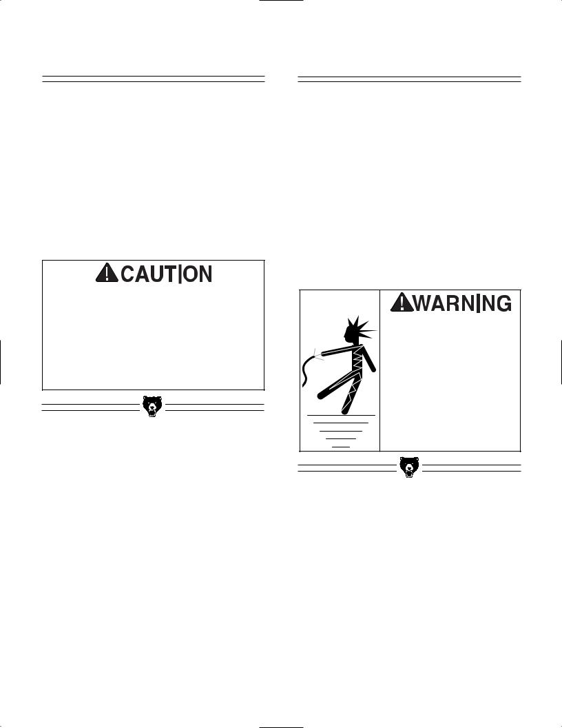
Do not use gasoline or other petroleum-based solvents to clean with. They have low flash points which makes them extremely flammable. A risk of explosion and burning exists if these p r o d u c t s a r e u s e d . Serious personal injury may occur.
Do not smoke while using solvents. A risk of explosion or fire exists and may result in serious personal injury.
Many of the solvents commonly used to clean machinery can be toxic when inhaled or ingested. Always work in wellventilated areas far from potential ignition sources when dealing with solvents. Use care when disposing of waste rags and towels to be sure they do not create fire or environmental hazards.
G1019 14'' Bandsaw
Site Considerations
FLOOR LOAD
Your Model G1019 Bandsaw represents a moderately large weight load in a small footprint. Most commercial or home shop floors should be sufficient to carry the weight of the Model G1019. If you question the strength of your floor, you can opt to reinforce it.
WORKING CLEARANCES
Working clearances can be thought of as the distances between machines and obstacles that allow safe operation of every machine without limitation. Consider existing and anticipated machine needs, size of material to be processed through each machine, and space for auxiliary stands and/or work tables. Also consider the relative position of each machine to one another for efficient material handling. Be sure to allow yourself sufficient room to safely run your machines in any foreseeable operation.
LIGHTING AND OUTLETS
Lighting should be bright enough to eliminate shadow and prevent eye strain. Electrical circuits should be dedicated or large enough to handle combined motor amp loads. Outlets should be located near each machine so power or extension cords are not obstructing high-traffic areas. Be sure to observe local electrical codes for proper installation of new lighting, outlets, or circuits.
Make your shop “child safe.” Ensure that your workplace is inaccessible to children by closing and locking all entrances when you are away. Never allow visitors in your shop when assembling, adjusting or operating equipment.
-9-
SECTION 4: ASSEMBLY
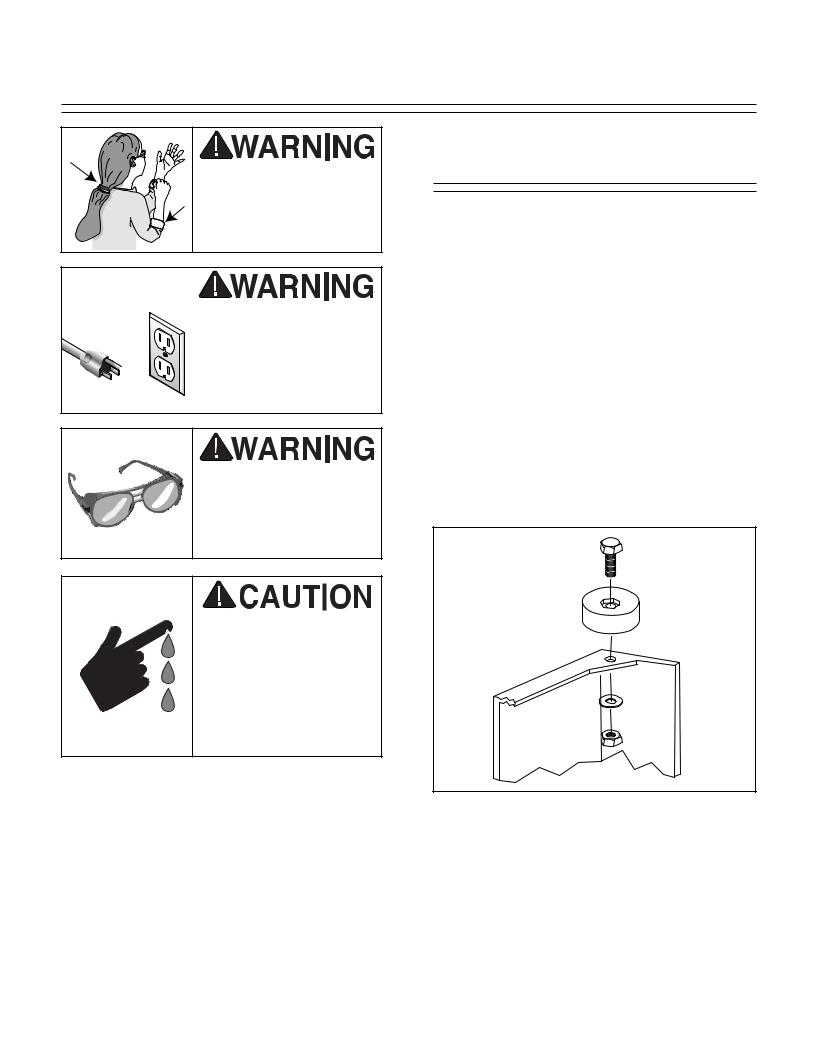
Keep clothing rolled up and out of the way of machinery and keep hair pulled back.
Disconnect power to the machine when performing any maintenance or assembly. Failure to do this may result in serious personal injury.
Wear safety glasses during the entire assembly process. Failure to comply may result in serious personal injury.
Some metal parts may have sharp edges on them after they are formed. Please examine the edges of all metal parts before handling them. Failure to do so could result in injury.
Stand
The Model G1019 Bandsaw stand is an A-frame, panel-style stand. The front and rear panels are connected with one panel at the top and two cross braces near the bottom.
Sometimes sheet metal parts have a tendency to ''spring'' after they are formed. For this reason, you may need to use a little extra force to align holes to insert bolts.
1.Start with the stand panel with the switch mounted in it. Turn the panel upside down and attach the rubber feet using (2) 1⁄4''-20 x 1'' Phillips® head screws, (2) flat washers and (2) hex nuts provided. Tighten down. See Figure 3. Repeat this step with the second stand panel.
Figure 3. Attach rubber feet first.
-10- |
G1019 14'' Bandsaw |

2.Stand the panels up so the rubber feet are on the floor. Attach two cross braces to one of the side panels using (4) 1⁄4''-20 x 1⁄2'' carriage bolts, flat washers and hex nuts provided. Next, attach the other side panel to the cross braces already mounted. See Figure 4. Note: Do not tighten any fasteners at this time.
Cross Braces
Figure 4. Attach cross braces.
3.Now, turn the stand over and attach the motor support plate using (4) 5⁄16''-18 x 3⁄4'' hex bolts, (8) washers and (4) hex nuts. See Figure 5.
Motor
Support
Plate
Figure 5. Install motor support plate.
4.Turn the stand right side up and attach the motor mount plate to the motor mount support plate using (4) 5⁄16"-18 x 3⁄4" hex bolts,
(8)flat washers and (4) hex nuts. See
Figure 6.
Motor
Mount
Plate
Figure 6. Add motor mount plate.
5.Mount the double bend brace to the motor mount plate. Use (2) 5⁄16''-18 x 3⁄4'' hex bolts,
(8)flat washers and (2) hex nuts. See
Figure 7.
Double
Bend
Brace
Figure 7. Mount double bend brace.
G1019 14'' Bandsaw |
-11- |

6.Attach the right angle brace to the bottom of the top panel using (2) 5⁄16''-18 x 1⁄2'' carriage bolts, (2) flat washers and (2) hex nuts. Finger tighten only. See Figure 8.
Right
Angle
Brace
Figure 8. Attach right angle brace.
7.Install the top panel using (10) 5⁄16''-18 x 1⁄2'' carriage bolts, (10) flat washers and (10) hex nuts. It may be necessary to wiggle the panels a bit to line up the bolt holes. Finger tighten only. See Figure 9.
Top
Panel 
Figure 9. Install top panel.
8.Place the drive pulley on the motor shaft and line up the keyways. Insert the key and tighten down the pulley setscrew. See
Figure 10.
Drive Pulley
Figure 10. Drive pulley placed on shaft.
9.Lay the stand on its side. Carefully set the motor on the motor bracket (see Figure 11) and line up the holes. Secure the motor using (4) 5⁄16''-18 x 1'' hex bolts, (4) hex nuts and (8) flat washers, finger tight only. Slide the motor to the top of the stand as far as it will go. Tighten the top two motor bolts down leaving the bottom two finger tight. Set the stand upright at this time.
Figure 11. Place drive pulley.
-12- |
G1019 14'' Bandsaw |
Switch
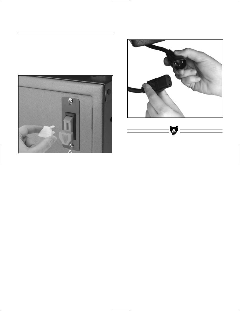
The switch is pre-mounted on the bandsaw unit. To lock-out the switch, you must unplug the safety key from the top of the paddle as shown in Figure 12. Never subsitute unplugging the machine from the power source with removing the lock-out key from the switch.
Figure 12. Removing lock-out key from switch.
To connect the switch power to the motor, plug the male end into the female end as shown in
Figure 13.
Figure 13. Connecting switch to motor.
G1019 14'' Bandsaw |
-13- |
 Loading...