


15" PLANER
MODEL G1021
INSTRUCTION MANUAL
COPYRIGHT © 1986 BY GRIZZLY INDUSTRIAL, INC. REG.# TX 3 170 572
WARNING: NO PORTION OF THIS MANUAL MAY BE REPRODUCED IN ANY SHAPE OR FORM WITHOUT THE WRITTEN APPROVAL OF GRIZZLY INDUSTRIAL, INC.
REVISED FEBRUARY, 1999. PRINTED IN U.S.A

|
Table Of Contents |
|
|
|
PAGE |
1. |
SAFETY .......................................................................................................................... |
3 |
|
SAFETY SYMBOLS .................................................................................................. |
3 |
|
SAFETY INSTRUCTIONS FOR POWER TOOLS ................................................ |
3-4 |
|
ADDITIONAL SAFETY INSTRUCTIONS FOR PLANERS........................................ |
5 |
2. |
CIRCUIT REQUIREMENTS .......................................................................................... |
6 |
|
220V OPERATION .................................................................................................... |
6 |
|
FUSING .................................................................................................................... |
6 |
|
GROUNDING ............................................................................................................ |
6 |
|
EXTENSION CORDS ................................................................................................ |
6 |
3. |
INTRODUCTION ............................................................................................................ |
7 |
|
COMMENTARY ........................................................................................................ |
7 |
|
UNPACKING.............................................................................................................. |
8 |
|
PIECE INVENTORY .................................................................................................. |
8 |
|
CLEAN UP ................................................................................................................ |
9 |
|
SITE CONSIDERATIONS ........................................................................................ |
9 |
4. |
ASSEMBLY .................................................................................................................. |
10 |
|
OVERVIEW.............................................................................................................. |
10 |
|
OPTIONAL STAND ................................................................................................ |
10 |
|
PLANER UNIT ........................................................................................................ |
11 |
|
STARTER SWITCH ................................................................................................ |
11 |
|
HANDWHEEL .......................................................................................................... |
12 |
|
KNIFE SETTING JIG .............................................................................................. |
12 |
|
EXTENSION ROLLERS .......................................................................................... |
13 |
|
DUST PORT ............................................................................................................ |
13 |
5. |
ADJUSTMENTS ............................................................................................................ |
14 |
|
OVERVIEW.............................................................................................................. |
14 |
|
GAUGE BLOCK ...................................................................................................... |
15 |
|
TABLE ADJUSTMENT ...................................................................................... |
15-16 |
|
KNIFE INSPECTION .......................................................................................... |
16-17 |
|
KNIFE ADJUSTMENT........................................................................................ |
17-18 |
|
CHIP BREAKER ................................................................................................ |
18-19 |
|
FEED ROLLER HEIGHT .................................................................................... |
19-20 |
|
FEED ROLLER PRESSURE.............................................................................. |
20-21 |
|
BED ROLLERS .................................................................................................. |
21-22 |
|
CHIP DEFLECTOR ................................................................................................ |
22 |
|
ANTI-KICKBACK .................................................................................................... |
23 |
|
BELTS ................................................................................................................ |
23-24 |
|
GEARBOX .......................................................................................................... |
24-25 |
|
THICKNESS SCALE .............................................................................................. |
26 |
G1021 15" Planer |
-3- |
|
Table Of Contents |
|
|
|
PAGE |
6. |
OPERATIONS .............................................................................................................. |
27 |
|
OVERVIEW.............................................................................................................. |
27 |
|
TABLE LOCKS ........................................................................................................ |
27 |
|
POWER FEED ........................................................................................................ |
28 |
|
HANDWHEEL .......................................................................................................... |
28 |
|
DEPTH LIMITER .................................................................................................... |
28 |
|
TEST RUN .............................................................................................................. |
29 |
|
WOOD SPECIES .................................................................................................... |
29 |
|
PLANING DIFFICULTIES........................................................................................ |
30 |
7. |
MAINTENANCE ............................................................................................................ |
31 |
|
GENERAL................................................................................................................ |
31 |
|
TABLE...................................................................................................................... |
31 |
|
KNIVES.................................................................................................................... |
31 |
|
LUBRICATION.................................................................................................... |
32-33 |
8. |
CLOSURE .................................................................................................................... |
34 |
|
MACHINE DATA...................................................................................................... |
35 |
|
TROUBLESHOOTING ............................................................................................ |
36 |
|
PARTS BREAKDOWN AND PARTS LISTS ...................................................... |
37-42 |
|
ADJUSTMENT BLOCK PATTERN.......................................................................... |
43 |
|
WARRANTY AND RETURNS ................................................................................ |
44 |
-4- |
G1021 15" Planer |

SECTION 1: SAFETY
 WARNING
For Your Own Safety Read Instruction Manual Before Operating This Equipment
The purpose of safety symbols is to attract your attention to possible dangers. This manual uses a series of symbols which are intended to convey the level of criticality of the safety message. The progression of symbols is described below. Remember that safety messages by themselves do not eliminate danger and are not a substitute for proper accident prevention measures.
NOTE |
This symbol is used to alert the user to useful information about |
safe and proper operation of the equipment. |
 CAUTION
 WARNING
 DANGER
Failure to obey a CAUTION symbol and notation may result in minor or moderate property damage or personal injury.
Failure to obey a WARNING symbol and notation can result in serious injury to yourself and others.
Failure to obey a DANGER symbol and notation WILL result in serious personal injury including loss of life or body parts.
 WARNING
Safety Instructions For Power Tools
1.KEEP GUARDS IN PLACE and in working order.
2.REMOVE ADJUSTING KEYS AND WRENCHES. Form habit of checking to see that keys and adjusting wrenches are removed from tool before turning on.
3.KEEP WORK AREA CLEAN. Cluttered areas and benches invite accidents.
4.DON’T USE IN DANGEROUS ENVIRONMENT. Don’t use power tools in damp or wet locations, or where any flammable or noxious fumes may exist. Keep work area well lighted.
5.KEEP CHILDREN AND VISITORS AWAY. All children and visitors should be kept a safe distance from work area.
6.MAKE WORK SHOP CHILD PROOF with padlocks, master switches, or by removing starter keys.
7.DON’T FORCE TOOL. It will do the job better and safer at the rate for which it was designed.
8.USE RIGHT TOOL. Don’t force tool or attachment to do a job for which it was not designed.
G1021 15" Planer |
-5- |

 WARNING
Safety Instructions For Power Tools
9.USE PROPER EXTENSION CORD. Make sure your extension cord is in good condition. When using an extension cord, be sure it is rated Hard Service (grade S) or better. Conductor size must be 16 A.W.G. for cords up to 100 feet in length. An undersized cord will cause a drop in line voltage resulting in loss of power and overheating. Your extension cord must also contain a ground wire and plug pin. Always repair or replace extension cords if they become damaged. Minimum Gage for extension cord:
12 A.W.G. 50ft
10 A.W.G. 100ft
10.WEAR PROPER APPAREL. Do not wear loose clothing, gloves, neckties, rings, bracelets, or other jewelry which may get caught in moving parts. Non-slip footwear is recommended. Wear protective hair covering to contain long hair.
11.ALWAYS USE SAFETY GLASSES. Also use face or dust mask if cutting operation is dusty. Everyday eyeglasses only have impact resistant lenses, they are NOT safety glasses.
12.SECURE WORK. Use clamps or a vise to hold work when practical. It’s safer than using your hand and frees both hands to operate tool.
13.DON’T OVERREACH. Keep proper footing and balance at all times.
14.MAINTAIN TOOLS WITH CARE. Keep tools sharp and clean for best and safest performance. Follow instructions for lubricating and changing accessories.
15.DISCONNECT TOOLS before servicing and changing accessories, such as blades, bits, cutters, and the like.
16.REDUCE THE RISK OF UNINTENTIONAL STARTING. Make sure switch is in off position before plugging in.
17.USE RECOMMENDED ACCESSORIES.
Consult the owner’s manual for recommended accessories. The use of improper accessories may cause risk of injury.
18.CHECK DAMAGED PARTS. Before further use of the tool, a guard or other part that is damaged should be carefully checked to determine that it will operate properly and perform its intended function. Check for alignment of moving parts, binding of moving parts, breakage of parts, mounting, and any other conditions that may affect its operation. A guard or other part that is damaged should be properly repaired or replaced.
19.DIRECTION OF FEED. Feed work into a blade or cutter against the direction of rotation of the blade or cutter only.
20.NEVER LEAVE TOOL RUNNING UNATTENDED. TURN POWER OFF. Don’t leave tool until it comes to a complete stop.
-6- |
G1021 15" Planer |

 WARNING
Additional Safety Instructions For Planers
1.Ensure that the machine sits firmly on the floor before use. Any “wobbles” must be corrected by shimming or blocking before operation.
2.This machine is not designed to process any other material except wood.
3.Never position fingers or thumbs near the infeed roller.
4.Long stock should always be fully supported by some type of support fixture.
5.Do not operate planer with dull or damaged knives.
6.Ensure that the planer is properly adjusted before using.
7.Do not remove excessive amounts of wood in a single pass.
8.Inspect your stock before planing. Reject stock with defects and foreign material.
9.Do not attempt to remove jams until power is disconnected and all moving parts have come to a complete stop.
10.Provide adequate infeed and outfeed space for operating the planer.
11.Do not plane wood less than 12" long and 1⁄4" thick.
12.Do not plane lumber with loose knots or knots that may become loose during planing.
 WARNING
Like all power tools, there is danger associated with the Model G1021 15" Planer. Use the tool with respect and caution to lessen the possibility of mechanical damage or operator injury. If normal safety precautions are overlooked or ignored. Serious personal injury may occur.
 WARNING
Always wear ANSI-approved safety glasses or goggles and hearing protection when operating equipment. Do not allow visitors into your workshop when testing or operating equipment unless similarly equipped. Serious personal injury may occur.
 CAUTION
No list of safety guidelines can be complete. Every shop environment is different. Always consider safety first, as it applies to your individual working conditions. Use this and other machinery with caution and respect. Failure to do so could result in serious person injury, damage to equipment or poor work results.
G1021 15" Planer |
-7- |
SECTION 2: CIRCUIT REQUIREMENTS
220V Operation |
|
Grounding |
|
|
|
|
|
|
The G1021 Planer motor is wired to operate at 220V only. A cordset without a 220V plug is included with the Model G1021. Plugs and receptacles can be purchased at your local hardware store or home center. When connecting to 220V, ensure that the electrical circuit is in fact a 220V circuit. Contact your local electrical contractor if uncertain about converting to 220V operation.
When operating at 220V, we recommend using a NEMA-style 6-15 plug and outlet as depicted in Figure 1. You may also “hard-wire” the planer directly to your panel, provided you place a disconnect switch near the machine. Check the electrical codes in your area for specifics on wiring requirements.
Figure 1. NEMA 6-15 220V/15A connector. |
Fusing
Under normal load, the Model G1021 draws about 12 amps. We recommend a 15-amp circuit or a 20-amp slow-blow fuse. A circuit rated any higher will not adequately protect the motor.
Equipment returned to us for service that shows evidence of being over-fused will be repaired or replaced totally at the customer’s expense, regardless of the present warranty status.
-8-
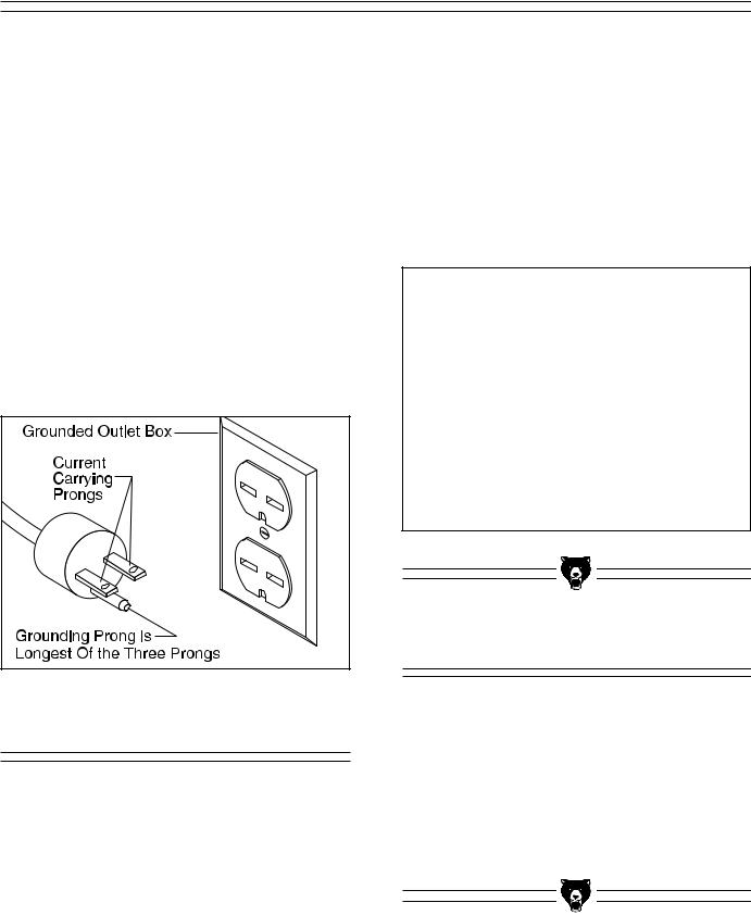
In the event of an electrical short, grounding reduces the risk of electric shock by providing a path of least resistance to disperse electric current. This tool is equipped with a power cord having an equipment-grounding conductor. The outlet must be properly installed and grounded in accordance with all local codes and ordinances.
 WARNING
This equipment must be grounded. Please ensure that this machine is continuously grounded from the motor to the machine frame and then to a known ground. Verify that any existing electrical outlet and circuit you intend to plug into is actually grounded. If it is not, it will be necessary to run a separate 12 A.W.G. copper grounding wire from the outlet to a known ground. Under no circumstances should the grounding pin from any three-pronged plug be removed. Serious injury may occur.
Extension Cords
If used, extension cords must be rated hard service – grade S – or better. Conductor size must be 12 AWG for cords up to 50 feet in length. Your extension cord must also contain a ground wire and plug pin. To ensure safe and dependable machine performance, inspect cords frequently for wear or damage. Replace or repair the cord immediately if evidence of damage is apparent.
G1021 15" Planer

SECTION 3: INTRODUCTION
Commentary
Grizzly Industrial, Inc. is proud to offer the Model G1021 15" Planer. The G1021 is part of Grizzly’s growing family of fine woodworking and metalworking machinery. When used according to the guidelines stated in this manual, you can expect years of trouble-free, enjoyable operation.
The Model G1021 is intended for home and professional use. The G1021 features a 2 HP, 220V single-phase motor with magnetic power switch, precision ground cast iron table, bed rollers, extension rollers and dual feed capability for maximum versatility.
Optional accessories are available through Grizzly Industrial and include a stand, mobile base, knife setting jigs and replacement knives.
We are also pleased to provide this manual with the Model G1021. It was written to guide you through assembly, review safety considerations, and cover general operating procedures. It represents our effort to produce the best documentation possible. If you have any comments regarding this manual, please write to us at the address below:
Grizzly Industrial, Inc.
C/O Technical Documentation
P.O. Box 2069
Bellingham, WA 98227-2069
Above all else, we stand behind our machines. We have an excellent service department at your disposal should the need arise. If you have any service questions or parts requests, please call or write to us at the location listed below.
Grizzly Industrial, Inc.
1203 Lycoming Mall Circle
Muncy, PA 17756
Phone: (570) 546-9663
Fax: (800) 438-5901 E-Mail: techsupport@grizzly.com Web Site: http://www.grizzly.com
G1021 15" Planer
To operate this, or any power tool, safely and efficiently, it is essential to become as familiar with its characteristics as possible. Take as much time as necessary to become acquainted with the Model G1021. The time you invest before you begin to use your machine will be time well spent. Also, read all of the safety procedures. If you do not understand something, DO NOT operate the machine.
The specifications, drawings, and photographs illustrated in this manual represent the Model G1021 as supplied when the manual was prepared. However, owing to Grizzly’s policy of continuous improvement, changes may be made at any time with no obligation on the part of Grizzly. Whenever possible, though, we send manual updates to all owners of a particular tool or machine. Should you receive one, we urge you to insert the new information with the old and keep it for reference.
 NOTE
NOTE
The information in this manual has been obtained from sources we believe to be reliable and as up-to-date as possible. We have included some important safety measures we believe to be essential for safe operation. While most safety measures are generally universal, Grizzly reminds you that each workshop is different and safety rules should be considered as they apply to your specific situation.
-9-

Unpacking
The bandsaw is shipped from the factory in a carefully packed carton. If you find the machine to be damaged after you’ve signed for delivery and the truck and driver are already gone, you will need to file a freight claim with the carrier. Save the containers and all packing materials for inspection by the carrier or their agent. Without the packing materials, filing a freight claim can be difficult. If you need advice regarding this situation, please call us immediately.
 WARNING
The G1021 is a heavy machine with a 475 lb. shipping weight. DO NOT over-exert yourself while unpacking or moving your machine – get assistance. In the event that your planer must be moved up or down a flight of stairs, be sure that the stairs are capable of supporting the combined weight of people and the machine. Failure to use care while assembling or moving could result in serious personal injury.
Parts Inventory
Take a quick inventory of the parts and put them aside for assembly later. After all the parts have been removed from the container, you should have:
•Planer Unit
•Dust Port
•Roller Extensions
•Hand Wheel
•Stand Top (Optional)
•Stand Legs (Optional)
•Stand Braces (Optional)
Now is a good time to inventory the fasteners required for assembly:
Hardware |
Qty |
Cap Screw 6mm - 1.0 x 12 |
3 |
Lock Washer 6mm |
3 |
Hex Bolts 6mm - 1.0 x 12 |
3 |
Hex Nuts 6mm - 1.0 |
3 |
Washers 6mm |
6 |
Knife Setting Jig Rod |
1 |
Knife Setting Jig Brackets |
2 |
E-clips |
2 |
Allen® Wrench 3mm |
1 |
Allen® Wrench 4mm |
1 |
Allen® Wrench 5mm |
1 |
Allen® Wrench 6mm |
1 |
Open End Wrench 8-10mm |
1 |
Open End Wrench 12-14mm |
1 |
Handle |
1 |
Hex Nut 10mm - 1.25 |
1 |
Flat Washer 10mm |
1 |
Scale |
1 |
Hex Bolts 8mm -1.25 x 20 |
6 |
Flat Washers 8mm |
6 |
Setscrews 8mm - 1.25 x 12 |
6 |
Stand Hardware (Optional) |
Qty |
Carriage Bolts 5⁄16" - 18 x 5⁄8" |
24 |
Hex Nuts 5⁄16" - 18 |
28 |
Flat Washers 5⁄16" |
24 |
Hex Bolts 5⁄16" - 18 x 2" |
4 |
Fender Washers |
8 |
In the event that any parts are missing, we will be happy to replace them. Contact our Customer Service number for assistance. If any non-propri- etary parts such as nuts, bolts or washers are missing, we will be happy to replace these too, but for the sake of expediency, these items can be obtained at your local hardware store.
 CAUTION
Some die-cut metal parts may have sharp edges (called “flashing”) on them after they are formed. Please examine the edges of all die-cut metal parts before handling them. Failure to do so could result in injury.
|
|
|
|
|
|
|
|
-10- |
|
|
G1021 15" Planer |
|
|
Clean Up
The unpainted surfaces are coated with a waxy oil to protect it from corrosion during shipment. Remove the protective coating with common paint thinner (mineral spirits) and paper towels. Do not use gasoline or other petroleum based solvents because of their extremely low flash points. Do not use chlorine-based solvents – if you happen to splash some onto a painted surface, you’ll ruin the finish.
 WARNING
Follow the safety rules listed below when working with solvents.
1.Read and follow all directions and warnings on the solvent label.
2.Work only in a well ventilated area.
3.Do not work near any type of open flame (e.g., pilot lights, kerosene heaters, and so on).
4.DO NOT smoke while working with flammable material.
5.Paper towels from the cleaning process are extremely combustible. Dispose of waste towels so they do not create a fire hazard.
 CAUTION
Many of the solvents commonly used to clean machinery can be highly flammable, and toxic when inhaled or ingested. Always work in well-ventilated areas far from potential ignition sources when dealing with solvents. Use care when disposing of waste rags and towels to be sure they do not create fire or environmental hazards. Keep children and animals safely away when cleaning and assembling this machine.
Site Considerations
FLOOR LOAD
Your G1021 Planer represents a relatively large weight load in a small footprint. Most commercial floors are suitable for the Model G1021. Some residential floors may require additional support to accommodate both machine and operator.
WORKING CLEARANCES
Working clearances can be thought of as the distances between machines and obstacles that allow safe operation of every machine without limitation. Consider existing and anticipated machine needs, size of material to be processed through each machine, and space for auxiliary stands and/or work tables. Also consider the relative position of each machine to one another for efficient material handling. Be sure to allow yourself sufficient room to safely run your machines in any foreseeable operation.
LIGHTING AND OUTLETS
Lighting should be bright enough to eliminate shadow and prevent eye strain. Electrical circuits should be dedicated or large enough to handle combined motor amp loads. Outlets should be located near each machine so power or extension cords are not obstructing high-traffic areas. Be sure to observe local electrical codes for proper installation of new lighting, outlets, or circuits.
 CAUTION
Make your shop “child safe”. Ensure that your workplace is inaccessible to youngsters by closing and locking all entrances when you are away. Never allow visitors in your shop when assembling, adjusting or operating equipment.
|
|
|
|
|
|
|
|
|
|
|
|
G1021 15" Planer |
-11- |
||
SECTION 4: ASSEMBLY
Overview
Most of your G1021 Planer has been assembled at the factory, but some parts must be assembled or installed after delivery. We have organized the assembly process into steps. Please follow along in the order presented here.
TOOLS REQUIRED: Most of the tools required for assembly are included with the planer. However, you will also need a Phillips® and regular screwdriver as well as feeler gauge for adjustments later on.
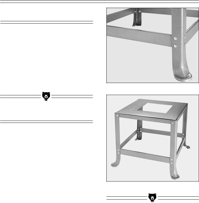
Figure 2. Stand crossbracing in place.
Optional Stand
To begin stand assembly, keep all the stand parts within easy reach. To ease assembly, build the stand upside down on a bench and then place it upright on the floor.
1.Place the stand top upside down on your bench.
2.Attach each of the four legs to the stand top with carriage bolts, washers and nuts provided. Do not over tighten. The legs attach to the outside of the stand top. See Figure 3.
3.Attach each of the four braces to the stand legs with carriage bolts, washers and nuts provided. Do not over tighten. The braces attach to the inside of the legs. See Figure 2.
4.Flip the stand right side up and place on the floor. Check to see if the stand is symmetrical from two adjacent sides. Adjust if necessary and securely tighten all nuts.
Figure 3. Fully assembled stand.
-12- |
G1021 15" Planer |
Planer Unit
TO MOUNT THE PLANER:
1.Using the lifting handles shown in Figure 4, place the planer on the stand and align the four holes in the base over the four mounting holes in the stand.
2.Secure the planer base to the stand with the four hex bolts, nuts, washer and fender washers provided.
 CAUTION
This planer is relatively heavy and awkward to handle. We strongly recommend that you get assistance. It will require at least two people to lift the planer onto the stand. Lifting without ample assistance could result in serious injury and/or damage to your machine. The planer unit may also be unstable until it is permanently mounted to the stand. Use care so the planer unit does not slide or tip. If placing the planer on a shop-built stand, ensure that the stand is stable and designed to carry the weight of the planer. Always bolt the planer to any stand including a shop-built stand.
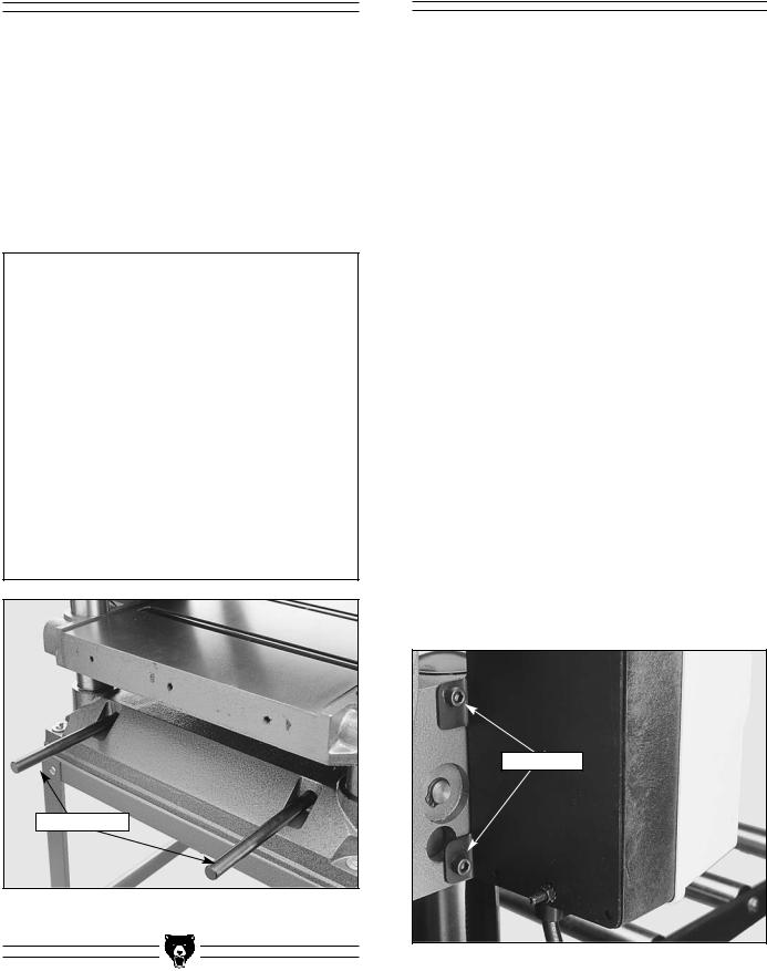
Lifting Handles
Figure 4. Location of lifting handles.
G1021 15" Planer
Starter Switch
The thermally protected, magnetic switch protects the motor from overload and the operator in case power is interrupted. If power is interrupted, the planer will not turn on when power resumes without first pressing the ON button.
The switch must be secured to the planer unit. The cap screws used for this purpose are already partially screwed in.
1.Unscrew the cap screws from the planer body for mounting the switch. See Figure 5.
2.Support the switch and screw the cap screws back in.
To connect the switch power leads to the motor:
1.Remove the motor junction box cover and slip the power cord through the cable clamp. Secure the cable clamp with a screwdriver.
2.Attach the two power leads to the motor terminals according to the wiring diagram supplied with this manual.
3.Attach the grounding terminal (green wire) to the motor frame via the ground screw located inside the junction box.
4.Re-attach the motor junction box cover.
Cap Screws
Figure 5. Starter switch attachment.
-13-
Handwheel |
|
Knife Setting Jig |
|
|
|
|
|
|
The handwheel is used to raise and lower the planer table. Each complete revolution raises the table 5⁄32" (4mm).
TO MOUNT THE HANDWHEEL:
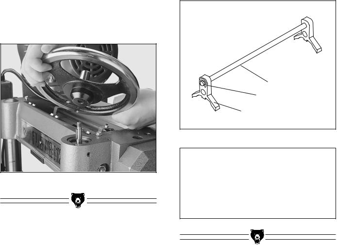
1.Place the handwheel over the keyed shaft on the planer body. Make sure the key on the shaft and the keyway on the handwheel line up. The handwheel shaft is at the front right of the planer. See Figure 6.
2.Press the direction scale over the keyed shaft so it fits into the depression in the top of the handwheel.
3.Secure the handwheel with the 10mm - 1.25 hex nut and washer provided.
Figure 6. Handwheel attachment.
The knife setting jig has been provided to make knife setting quick and easy. See Figure 7.
TO ASSEMBLE THE KNIFE SETTING JIG:
1.Snap one of the E-clips over the notch on one end of the knife setting rod.
2.Slide the cast aluminum knife setting jig brackets onto the rod.
3.Snap the other E-clip onto the notch at the other end of the knife setting jig rod.
Jig Rod |
E-clip |
Jig Bracket |
Figure 7. Knife setting jig components.
 CAUTION
Planer knives are dangerously sharp. Use extreme caution when working near cutting surfaces. Failure to exercise care while working near knives could result in severe injury.
-14- |
|
G1021 15" Planer |
|
 Loading...