


 Loading...
GA-8SIMLFS
P4 Titan-DDR Motherboard
USER’S MANUAL
Pentium®4 Processor Motherboard
Rev 2001

English
Table of Content |
|
WARNING! ............................................................................................... |
3 |
Chapter 1 Introduction ............................................................................. |
4 |
Features Summary ...................................................................................... |
4 |
GA-8SIMLFS Motherboard Layout ............................................................. |
6 |
Chapter 2 Hardware Installation Process ................................................ |
7 |
Step 1: Install the Central Processing Unit (CPU)....................................... |
8 |
Step 1-1 : CPU Installation.......................................................... |
8 |
Step 1-2 : CPU Heat Sink Installation ......................................... |
9 |
Step 2: Install memory modules ................................................................ |
10 |
Step 3: Install expansion cards ................................................................. |
11 |
Step 4: Connect ribbon cables, cabinet wires, and power supply ........... |
12 |
Step 4-1 : I/O Back Panel Introduction ..................................... |
12 |
Step 4-2 : Connectors Introduction .......................................... |
14 |
GA-8SIMLFS Motherboard |
- 2 - |

WARNING!
Computer motherboards and expansion cards contain very delicate Integrated Circuit (IC) chips. To protect them against damage from static electricity, you should follow some precautions whenever you work on your computer.
1.Unplug your computer when working on the inside.
2.Use a grounded wrist strap before handling computer components. If you do not have one, touch both of your hands to a safely grounded object or to a metal object, such as the power supply case.
3.Hold components by the edges and try not touch the IC chips, leads or connectors, or other components.
4.Place components on a grounded antistatic pad or on the bag that came with the components whenever the components are separated from the system.
5.Ensure that the ATX power supply is switched off before you plug in or remove the ATX power connector on the motherboard.
Installing the motherboard to the chassis…
If the motherboard has mounting holes, but they don’t line up with the holes on the base and there are no slots to attach the spacers, do not become alarmed you can still attach the spacers to the mounting holes. Just cut the bottom portion of the spacers (the spacer may be a little hard to cut off, so be careful of your hands). In this way you can still attach the motherboard to the base without worrying about short circuits. Sometimes you may need to use the plastic springs to isolate the screw from the motherboard PCB surface, because the circuit wire may be near by the hole. Be careful, don’t let the screw contact any printed circuit write or parts on the PCB that are near the fixing hole, otherwise it may damage the board or cause board malfunctioning.
English
- 3 - |
Introduction |

English
Chapter 1 Introduction
Features Summary
Form Factor |
y |
22.9cm x 24.3cm Micro ATX size form factor, 4 layers PCB. |
|
CPU |
y |
Socket 478 for Intel® Micro FC-PGA2 Pentium® 4 processor |
|
|
y |
Support Intel ® Pentium ® 4 (Northwood, 0.13 m) processor |
|
|
y |
Intel Pentium®4 400MHz FSB |
|
|
y 2nd cache depends on CPU |
||
|
|
|
|
Chipset |
y |
SiS 650GX Host/Memory controller |
|
|
y SiS 961 MuTIOL Media I/O |
||
|
|
|
|
Memory |
y |
2 184-pin DDR DIMM sockets |
|
|
y |
Supports DDR266/200 SDRAM |
|
|
y Supports up to 2 un-buffer Double-sided DIMM DDR266/200 |
||
|
y Supports up to 2GB DDR DRAM (Max) |
||
|
y Supports only 2.5V DDR DIMM |
||
|
y Supports 64bit DRAM integrity mode |
||
|
|
|
|
I/O Control |
y |
W83697HF |
|
Slots |
y |
1 Universal AGP slot (1X/2X/4X) device support |
|
|
y 3 PCI slot supports 33MHz & PCI 2.2 compliant |
||
|
y 1 CNR(Communication and Networking Riser) Slot |
||
|
|
|
|
On-Board IDE |
y |
2 IDE bus master (UDMA33/ATA66/ATA100) IDE ports for up to 4 |
|
|
|
ATAPI devices |
|
|
y Supports PIO mode3,4 (UDMA 33/ATA66/ATA100) IDE & ATAPI |
||
|
|
CD-ROM |
|
|
|
|
|
On-Board Peripherals |
y |
1 Floppy port supports 2 FDD with 360K, 720K,1.2M, 1.44M |
|
|
|
and 2.88M bytes. |
|
y 1 Parallel port supports Normal/EPP/ECP mode y 1 Serial port (COMA),1 VGA port,COMB on board y 4 USB ports (Rear USB x 2,by optional cable)
y 1 FrontAudio Connector
y 1 Serial IRQ Connector y 1 IrDA connector for IR
to be continued......
GA-8SIMLFS Motherboard |
- 4 - |

Hardware Monitor |
y |
CPU/System Fan Revolution detect |
|
y |
CPU/System Fan Control |
|
y |
CPU Overheat Warning |
|
y |
System Voltage Detect |
|
|
|
On-Board Sound |
y |
AC97 CODEC |
|
y Line In/Line Out/Mic In/CD In /Game Port |
|
|
|
|
On-Board LAN |
y |
Builit in RTL8100L Chipset |
|
y |
1 RJ45 port |
|
|
|
On-Board VGA |
y |
Builit in SiS650GX Chipset |
PS/2 Connector |
y |
PS/2 Keyboard interface and PS/2 Mouse interace |
BIOS |
y |
Licensed Award BIOS, 2M bit Flash ROM |
|
|
|
Additional Features |
y |
PS/2 Keyboard power on by password |
|
y PS/2 Mouse power on |
|
|
y |
STR(Suspend-To-RAM) |
|
y |
AC Recovery |
|
y USB KB/Mouse wake up from S3 |
|
|
|
|
Please set the CPU host frequency in accordance with your processor’s specifications. We don’t recommend you to set the system bus frequency over the CPU’s specification because these specific bus frequencies are not the standard specifications for CPU, chipset and most of the peripherals. Whether your system can run under these specific bus frequencies properly will depend on your hardware configurations, including CPU, Chipsets,SDRAM,Cards….etc.
English
- 5 - |
Introduction |

English
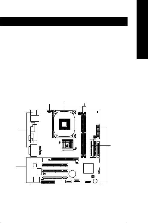
GA-8SIMLFS Motherboard Layout
GA-8SIMLFS Motherboard |
- 6 - |
Chapter 2 Hardware Installation Process
To set up your computer, you must complete the following steps: Step 1- Install the Central Processing Unit (CPU)
Step 2- Install memory modules Step 3- Install expansion cards
Step 4- Connect ribbon cables, cabinet wires, and power supply Step 5- Setup BIOS software
Step 6- Install supporting software tools
Step4 |
Step1 |
Step 2 |
Step 4 |
|
|
|
|
Step 4 |
Step3 |
|
|
English
- 7 - |
Hardware Installation Process |

English
Step 1: Install the Central Processing Unit (CPU)
Step 1-1 : CPU Installation
Pin1 indicator |
Pin1 indicator |
CPU Top View |
CPU Bottom View |
Socket Actuation Lever |
Pin1 indicator |
|
1.Pull up the CPU socket lever and up to 90-degree angle.
3.Press down the CPU socket lever and finish CPU installation.
2.Locate Pin 1 in the socket and look for a (golden) cut edge on the CPU upper corner. Then insert the CPU into the socket.
Please make sure the CPU type is supported by the motherboard.
If you do not match the CPU socket Pin 1 and CPU cut edge well, it will cause improper installation. Please change the insert orientation.
GA-8SIMLFS Motherboard |
- 8 - |

Step 1-2: CPU Heat Sink Installation
English
1. Hook one end of the cooler |
2. Hook the other end of the |
bracket to the CPU socket first. |
cooler bracket to the CPU |
|
socket. |
Please use Intel approved cooling fan.
We recommend you to apply the thermal tape to provide better heat conduction between your CPU and heatsink.
(The CPU cooling fan might stick to the CPU due to the hardening of the thermal paste. During this condition if you try to remove the cooling fan, you might pull the processor out of the CPU socket alone with the cooling fan, and might damage the processor. To avoid this from happening, we suggest you to either use thermal tape instead of thermal paste, or remove the cooling fan with extreme caution.)
Make sure the CPU fan power cable is plugged in to the CPU fan connector, this completes the installation.
Please refer to CPU heat sink user’s manual for more detail installation procedure.
- 9 - |
Hardware Installation Process |
English
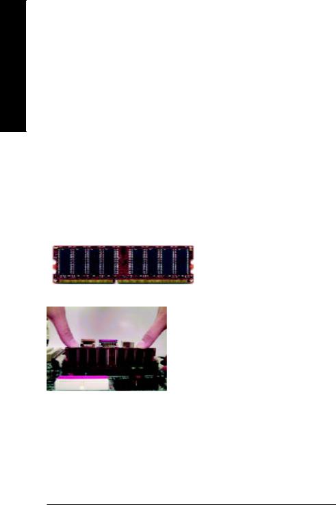
Step 2: Install memory modules
The motherboard has 2 dual inline memory module (DIMM) sockets. The BIOS will automatically detects memory type and size. To install the memory module, just push it vertically into the DIMM Slot
.The DIMM module can only fit in one direction due to the notch. Memory size can vary between sockets.
Total Memory Sizes With Unbuffered DDR DIMM
Devices used on DIMM |
1 DIMM x 64 / x 72 |
2 DIMMs x 64 / x 72 |
||||
|
|
|
|
|
|
|
64 |
Mbit (2Mx8x4 banks) |
128 |
MBytes |
256 |
MBytes |
|
64 |
Mbit (1Mx16x4 banks) |
32 MBytes |
64 MBytes |
|||
128 |
Mbit(4Mx8x4 banks) |
256 |
MBytes |
512 |
MBytes |
|
128 |
Mbit(2Mx16x4 banks) |
64 MBytes |
128 |
MBytes |
||
256 |
Mbit(8Mx8x4 banks) |
512 MBytes |
1 GBytes |
|||
256 |
Mbit(4Mx16x4 banks) |
128 |
MBytes |
256 |
MBytes |
|
512 |
Mbit(16Mx8x4 banks) |
1 GBytes |
2 GBytes |
|||
512 |
Mbit(8Mx16x4 banks) |
256 |
MBytes |
512 |
MBytes |
|
DDR
1.The DIMM slot has a notch, so the
DIMMmemory module can only fit in one direction.
2.Insert the DIMM memory module verticallyinto the DIMM slot. Then push it down.
3.Close the plastic clip at both edges of theDIMM slots to lock the DIMM module.
Reverse the installation steps when you wish to remove the DIMM module.
Please note that the DIMM module can only fit in one direction due to the one notches. Wrong orientation will cause improper installation. Please change the insert orientation.
GA-8SIMLFS Motherboard |
- 10 - |
DDR Introduction
Established on the existing SDRAM industry infrastructure, DDR (Double Data Rate) memory is a high performance and cost-effective solution that allows easy adoption for memory vendors, OEMs and system integrators.
DDR memory is a sensible evolutionary solution for the PC industry that builds on the existing SDRAM infrastructure, yet makes awesome advances in solving the system performance bottleneck by doubling the memory bandwidth. DDR SDRAM will offer a superior solution and migration path from existing SDRAM designs due to its availability, pricing and overall market support. PC2100 DDR memory (DDR266) doubles the data rate through reading and writing at both the rising and falling edge of the clock, achieving data bandwidth 2X greater than PC133 when running with the same DRAM clock frequency. With peak bandwidth of 2.1GB per second, DDR memory enables system OEMs to build high performance and low latency DRAM subsystems that are suitable for servers, workstations, highend PC's and value desktop SMA systems. With a core voltage of only 2.5 Volts compared to conventional SDRAM's 3.3 volts, DDR memory is a compelling solution for small form factor desktops and notebook applications.
Step 3: Install expansion cards
1.Read the related expansion card’s instruction document before install the expansion card into the computer.
2.Remove your computer’s chassis cover, necessary screws and slot bracket from the computer.
3.Press the expansion card firmly into expansion slot in motherboard.
4.Be sure the metal contacts on the card are indeed seated in the slot.
5.Replace the screw to secure the slot bracket of the expansion card.
6.Replace your computer’s chassis cover.
7.Power on the computer, if necessary, setup BIOS utility of expansion card from BIOS.
8.Install related driver from the operating system.
English
Please carefully pull out the small whitedrawable bar at the end of the AGP slot when you try to install/ Uninstall the AGP card. Please align the AGP card to the onboard
AGP Card AGP slot and press firmly down on the slot .Make sure your AGP card
is locked by the small whitedrawable bar.
- 11 - |
Hardware Installation Process |
English
Step 4: Connect ribbon cables, cabinet wires, and power supply
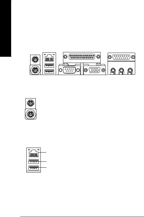
Step4-1:I/O Back Panel Introduction
Y |
Z |
[ |
X |
|
|
|
|
\ |
X PS/2 Keyboard and PS/2 Mouse Connector
PS/2 Mouse Connector (6 pin Female)
PS/2 Keyboard Connector (6 pin Female)
Y USB & LAN Connector
LAN
USB 0
USB 1
This connector supports standard PS/2 keyboard and PS/2 mouse.
Before you connect your device(s) into USB connector(s), please make sure your device(s) such as USB keyboard,mouse, scanner, zip, speaker..etc. Have a standard USB interface.Also make sure your OS (Win 95 with USB supplement, Win98, Windows 2000, Windows ME, Win NT with SP 6) supports USB controller. If your OS does not support USB controller, please contact OS vendor for possible patch or driver upgrade. For more information please contact your OS or device(s) vendors.
GA-8SIMLFS Motherboard |
- 12 - |
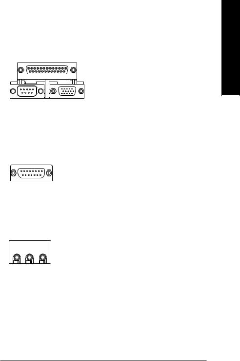
Z Parallel Port , Serial Port and VGA Port (LPT/COMA/VGA)
Parallel Port (25 pin Female)
COMA |
VGA |
Serial Port |
VGA Port |
(9 pin Male) |
(15 pin Female) |
This connector supports 1 standard COM port ,1 Parallel port and 1 VGA port. Device like printer can be connected to Parallel port ; mouse and modem etc can be connected to Serial ports.
[ Game /MIDI Ports
Joystick/ MIDI (15 pin Female)
\ Audio Connectors
|
|
|
|
Line Out |
MIC In |
||
|
|
|
|
Line In
This connector supports joystick, MIDI keyboard and other relate audio devices.
After install onboard audio driver, you may connect speaker to Line Out jack, micro phone to MIC In jack. Device like CD-ROM , walkman etc can be connected to Line-In jack.
English
- 13 - |
Hardware Installation Process |

English
Step4-2: Connectors Introduction |
|
|
|
|
A |
|
|
B |
|
|
|
|
|
C |
|
|
|
|
D |
O |
|
|
|
E |
N |
|
|
|
|
|
|
|
|
F |
|
|
|
|
G |
|
|
|
|
H |
M |
L |
K |
J |
I |
A) |
ATX_12V |
K) F_USB |
B) |
CPU_FAN |
L) BATTERY |
C) |
ATX |
M) COMB |
D) |
PWR_FAN |
N) F_AUDIO |
E) |
FDD/IDE1/IDE2 |
O) CD_IN |
F) |
IR |
|
G) |
CLR_CMOS |
|
H) |
SYS_FAN |
|
I) |
CI |
|
J) |
F_PANEL |
|
GA-8SIMLFS Motherboard |
- 14 - |

A) ATX_12V ( +12V Power Connector)
3 |
4 |
+12V |
+12V |
GND |
GND |
1 |
2 |
This connector (ATX +12V) suppliesthe CPU operation voltage (Vcore).
If this " ATX+ 12V connector" is not connected, system cannot boot.
B ) CPU_FAN (CPU FAN Connector)
Sense +12V/Control GND
 1
1
Please note, a proper installation of the CPU cooler is essential to prevent the CPU from running under abnormal condition or damaged by overheating.The CPU fan connector supports Max. current up to 600 mA.
H ) SYS_FAN (System FAN Connector) D )PWR_FAN (Power FAN Connector)
|
Sense |
1 |
+12V/Control |
GND |
I) CI (CASE OPEN)
Signal
GND
|
Sense |
1 |
+12V/Control |
GND |
This 2 pin connector allows your system to enable or disable the system alarm if the sys tem case begin remove.


 1
1
English
- 15 - |
Hardware Installation Process |
Loading...