


 Loading...
GA-H81TN GA-B85TN GA-H87TN GA-Q87TN
User's Manual
12ME0-H81TN0-00R

Motherboard
GA-H81TN
Motherboard
GA-H81TN
Sept. 23, 2013
Sept. 23, 2013
Motherboard
GA-B85TN
Motherboard
GA-B85TN
Sept. 23, 2013
Sept. 23, 2013
Motherboard
GA-H87TN
Motherboard
GA-H87TN
Sept. 23, 2013
Sept. 23, 2013
Motherboard
GA-Q87TN
Motherboard
GA-Q87TN
Sept. 23, 2013
Sept. 23, 2013

Copyright
© 2013 GIGA-BYTE TECHNOLOGY CO., LTD. All rights reserved.
The trademarks mentioned in this manual are legally registered to their respective owners.
Disclaimer
Information in this manual is protected by copyright laws and is the property of GIGABYTE. Changes to the specifications and features in this manual may be made by GIGABYTE without prior notice. No part of this manual may be reproduced, copied, translated, transmitted, or published in any form or by any means without GIGABYTE's prior written permission.
Documentation Classifications
In order to assist in the use of this product, GIGABYTE provides the following types of documentations:
For detailed product information, carefully read the User's Manual.
For product-related information, check on our website at:
http://www.gigabyte.com

Table of Contents
Box Contents.................................................................................................................... |
|
|
6 |
GA-H81TN/GA-B85TN/GA-H87TN Motherboard Layout |
.................................................7 |
||
GA-Q87TN Motherboard Layout...................................................................................... |
8 |
||
Chapter 1 Hardware Installation...................................................................................... |
9 |
||
1-1 |
Installation Precautions..................................................................................... |
9 |
|
1-2 |
Product Specifications.................................................................................... |
10 |
|
1-3 Installing the CPU and CPU Cooler................................................................ |
13 |
||
1-4 Installing the Memory/Expansion Card........................................................... |
13 |
||
1-5 |
Back Panel Connectors.................................................................................. |
14 |
|
1-6 |
Internal Connectors........................................................................................ |
16 |
|
Chapter 2 BIOS Setup................................................................................................... |
29 |
||
2-1 |
The Main Menu............................................................................................... |
31 |
|
2-2 |
Advanced Menu.............................................................................................. |
33 |
|
|
2-2-1 |
CPU Configuration.................................................................................................. |
34 |
|
2-2-2 |
SATA Configuration................................................................................................. |
36 |
|
2-2-3 |
Trusted Computing.................................................................................................. |
37 |
|
2-2-4 Intel (R) Rapid Start Technology............................................................................. |
38 |
|
|
2-2-5 Intel(R) Smart Connect Technology........................................................................ |
39 |
|
|
2-2-6 |
AMT Configuration.................................................................................................. |
40 |
|
2-2-7 |
Super IO Configuration........................................................................................... |
41 |
|
2-2-8 |
H/W Monitor............................................................................................................ |
42 |
2-3 |
Chipset Menu.................................................................................................. |
43 |
|
2-4 |
Boot Menu...................................................................................................... |
45 |
|
2-5 |
Security Menu................................................................................................. |
48 |
|
2-6 Save & Exit Menu........................................................................................... |
49 |
||
- 5 -
Box Contents
;; GA-H81TN, GA-B85TN, GA-H87TN or GA-Q87TN motherboard ;; Motherboard driver disk
;; User's Manual
;; I/O Shield (AIO Thin Mini-ITX x1, Standard Type x 1) ;; Screws kit for expansion cards
;; COM serial cable
;; Cable SATA Power x 1
•• The box contents above are for reference only and the actual items shall depend on the product package you obtain.
- 6 -
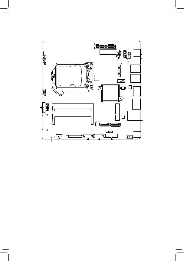
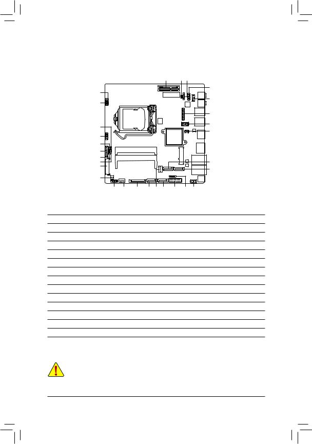
GA-H81TN/GA-B85TN/GA-H87TN Motherboard Layout
LCD_VCC WF_LED
FPD_PWR BL_SW
FUSB2_3 FUSB2_2 FUSB2_4
FPD
MON_SW


 LVDS
LVDS

PCIE4X |
|
|
|
|
EXT_CON |
SPKR |
|
|
|
MIC_IN |
|
|
|
|
|
|
CLR_CMOS |
|
LINE_OUT |
|
DMIC_CON |
CODEC |
|
|
|
||
|
|
AUDIO |
USBX_1 |
|
LPT |
FP |
|
BIOS |
|
||
|
|
|
|
Socket 1150 |
|
|
USB3_1 |
|
COM1 |
|
|
|
|
|
|
|
|
BATTERY |
|
|
Intel® H81j/ |
|
HDMI |
|
B85kH87• |
|
|
SO_DIMM1
SO_DIMM2
GA-H81TN GA-B85TN GA-H87TN
SATA_PWR
|
(Note) |
DP |
MPCIE1X |
GbERealtekLAN® |
|
|
LAN |
|
SYS_FAN |
|
|
SATA_2 SATA_3k• |
|
|
FUSB2_5 |
ATX_19V |
DC_IN |
|
||
SYS_PANEL CPU_FAN |
SATAIII_0 SATAIII_1 |
FUSB3 • |
MM Only for GA-H81TN. NN Only for GA-B85TN. OO Only for GA-H87TN.
(Note) The chip is located on the back of the motherboard. - 7 -
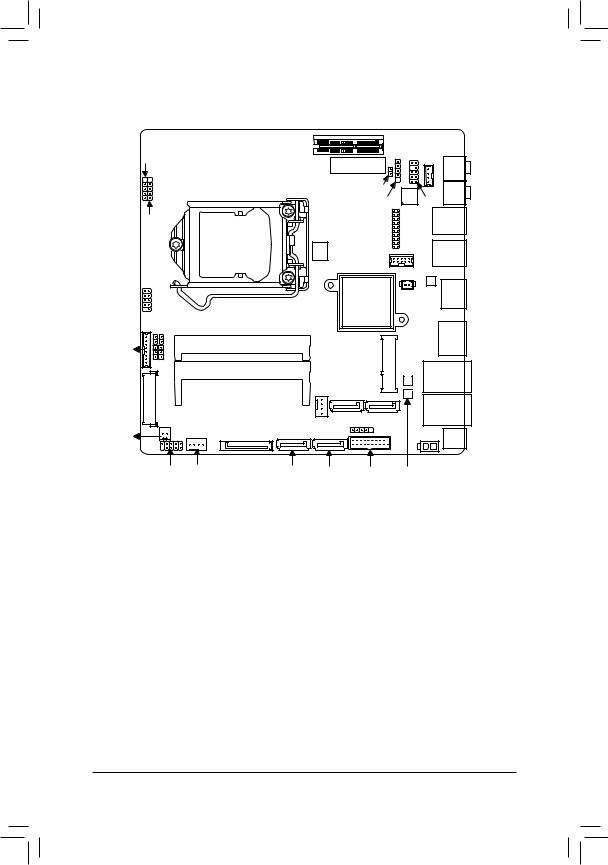
GA-Q87TN Motherboard Layout
FPD_PWR BLFUSB2_SW _3 FUSB2_2 FUSB2_4 LCD_VCC WF_LED
PCIE4X
BIOS
Socket 1150
EXT_CON |
SPKR |
||
|
MIC_IN |
||
|
|
||
CLR_CMOS |
|
LINE_OUT |
|
DMIC_CON |
CODEC |
||
|
|||
|
AUDIO |
USBX_1 |
|
LPT |
FP |
||
|
|||
COM1 |
|
USB3_1 |
|
|
|
||
|
BATTERY |
|
|
Intel® Q87 |
|
HDMI |
|
|
|
||
FPD |
SO_DIMM1 |
|
SO_DIMM2
|
LVDS |
GA-Q87TN |
|
|
|
_SW |
|
SATA_PWR |
MON |
|
|
|
SYS_PANEL CPU_FAN |
|
|
|
(Note) |
DP |
|
MPCIE1X |
GbERealtekLAN® |
LAN |
|
|
|
|
SYS_FAN |
|
|
|
SATAIII_2 SATAIII_3 |
LAN |
||
|
|||
FUSB2_5 |
|
ATX_19V DC_IN |
|
|
|
||
SATAIII_0 SATAIII_1 |
FUSB3 |
Intel® GbE LAN (Note) |
|
(Note) The chip is located on the back of the motherboard. - 8 -

Chapter 1 Hardware Installation
1-1 Installation Precautions
The motherboard contains numerous delicate electronic circuits and components which can become damaged as a result of electrostatic discharge (ESD). Prior to installation, carefully read the user's manual and follow these procedures:
•• Prior to installation, make sure the chassis is suitable for the motherboard.
•• Prior to installation, do not remove or break motherboard S/N (Serial Number) sticker or warranty sticker provided by your dealer. These stickers are required for warranty validation.
•• Always remove the AC power by unplugging the power cord from the power outlet before installing or removing the motherboard or other hardware components.
•• When connecting hardware components to the internal connectors on the motherboard, make sure they are connected tightly and securely.
•• When handling the motherboard, avoid touching any metal leads or connectors.
•• It is best to wear an electrostatic discharge (ESD) wrist strap when handling electronic components such as a motherboard, CPU or memory. If you do not have an ESD wrist strap, keep your hands dry and first touch a metal object to eliminate static electricity.
•• Prior to installing the motherboard, please have it on top of an antistatic pad or within an electrostatic shielding container.
•• Before unplugging the power supply cable from the motherboard, make sure the power supply has been turned off.
•• Before turning on the power, make sure the power supply voltage has been set according to the local voltage standard.
•• Before using the product, please verify that all cables and power connectors of your hardware components are connected.
•• To prevent damage to the motherboard, do not allow screws to come in contact with the motherboard circuit or its components.
•• Make sure there are no leftover screws or metal components placed on the motherboard or within the computer casing.
•• Do not place the computer system on an uneven surface.
•• Do not place the computer system in a high-temperature environment.
•• Turning on the computer power during the installation process can lead to damage to system components as well as physical harm to the user.
•• If you are uncertain about any installation steps or have a problem related to the use of the product, please consult a certified computer technician.
- 9 -
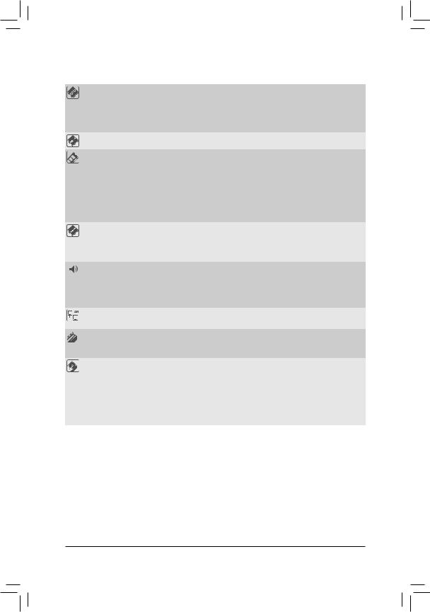
1-2 |
Product Specifications |
||
|
|
|
|
|
CPU |
Support for Intel® Core™ i7 processors/Intel® Core™ i5 processors/ |
|
|
|
|
Intel® Core™ i3 processors/Intel® Pentium® processors/Intel® Celeron® processors |
|
|
|
in the LGA1150 package (Supports up to 84W) |
|
|
|
(Go to GIGABYTE's website for the latest CPU support list.) |
|
|
L3 cache varies with CPU |
|
|
Chipset |
|
Intel® H81j/B85k/H87•/Q87m Express Chipset |
|
Memory |
2 x 1.5V DDR3 SO-DIMM sockets supporting up to 8 GB of system memory |
|
|
|
|
* Due to a Windows 32-bit operating system limitation, when more than 4 GB of |
|
|
|
physical memory is installed, the actual memory size displayed will be less than |
|
|
|
the size of the physical memory installed. |
|
|
Dual channel memory architecture |
|
|
|
Support for DDR3 1600/1333 MHz memory modules |
|
|
|
|
(Go to GIGABYTE's website for the latest supported memory speeds and |
|
|
|
memory modules.) |
|
Onboard Graphics |
|
Chipset: |
|
|
|
- 1 x HDMI 1.4 port, supporting a maximum resolution of 4096x2160 |
-1 x DisplayPort, supporting a maximum resolution of 2560x1600
-1 x LVDS connector
Audio |
|
Realtek® ALC887 codec |
|
High Definition Audio |
|
|
|
2/4/5.1/7.1-channel |
*To configure 5.1/7.1-channel audio, you have to use an HD front panel audio module and enable the multi-channel audio feature through the audio driver.
LAN |
1 x Realtek® GbE LAN chip (10/100/1000 Mbit) (LAN1) jk•m |
|
|
1 x Intel® GbE LAN chip (10/100/1000 Mbit) (LAN2) m |
|
Expansion Slots |
1 x PCI Express x4 slot (Supports 25W only) |
|
|
(The PCIEX4 slot conforms to PCI Express 3.0 standard.) |
|
|
1 x Mini PCI Express x1 slot |
|
Storage Interface |
Chipset: |
|
|
- |
2 x SATA 6Gb/s connectors (SATAIII 0/1); 1 x SATA 3Gb/s connector (SATAII |
|
|
2) j |
|
- |
3 x SATA6Gb/s connectors (SATAIII 0/1/3); 1 x SATA3Gb/s connector (SATAII |
|
|
2) k |
|
- |
4 x SATA 6Gb/s connectors (SATAIII 0/1/2/3) •m |
|
- |
1 x mSATA connector |
MM Only for GA-H81TN.
NN Only for GA-B85TN.
OO Only for GA-H87TN.
PP Only for GA-Q87TN.
- 10 -
USB |
Chipset: |
|
|
- 2 x USB 3.0/2.0 ports; 7 x USB 2.0/1.1 ports j |
|
|
- |
4 x USB 3.0/2.0 ports; 5 x USB 2.0/1.1 ports k |
|
- |
6 x USB 3.0/2.0 ports; 5 x USB 2.0/1.1 ports •m |
|
* USB 2.0/1.1 ports available through the internal USB headers (Card reader/Touch |
|
panel/webcam and other devices) |
Internal |
1 x 2-pin power connector |
Connectors |
1 x CPU fan header |
|
1 x system fan header |
|
2 x SATA 6Gb/s connectors j |
|
3 x SATA 6Gb/s connectors k |
|
4 x SATA 6Gb/s connectors •m |
|
1 x SATA 3Gb/s connector jk |
|
1 x mSATA connector |
|
1 x SATA power connector |
|
4 x USB 2.0/1.1 headers |
|
1 x serial port header |
|
1 x parallel port header |
|
1 x front panel header |
|
1 x front panel audio header |
|
1 x digital microphone header |
|
1 x AIO speaker header |
|
1 x LVDS connector |
|
1 x LVDS drive voltage header |
|
1 x flat panel display power header (both panel and backlight inverter) |
|
1 x flat panel display power connector |
|
1 x backlight switch header |
|
1 x flat panel display switch header |
|
1 x WIFI activity indicator LED header |
|
1 x Clear CMOS jumper |
Back Panel |
1 x HDMI port |
Connectors |
1 x DisplayPort |
|
4 x USB 3.0/2.0 ports k•m |
|
2 x USB 3.0/2.0 ports j |
|
2 x USB 2.0/1.1 ports j |
|
1 x RJ-45 port jk• |
|
2 x RJ-45 ports m |
|
2 x audio jacks (Line Out, Mic In) |
|
1 x DC-In power connector |
MM Only for GA-H81TN. NN Only for GA-B85TN. OO Only for GA-H87TN. PP Only for GA-Q87TN.
- 11 -

I/O Controller |
|
Nuvoton I/O Controller Chip |
|
|
|
Hardware Monitor |
|
System voltage detection |
|
|
CPU/System temperature detection |
|
CPU/System fan speed detection |
|
|
CPU fan speed control |
|
|
|
* For 4-pin CPU coolers only. |
|
|
* Whether the CPU fan speed control function is supported will depend on the CPU |
|
|
cooler you install. |
BIOS |
|
1 x 64 Mbit flash j |
|
1 x 128 Mbit flash k•m |
|
|
Use of licensed AMI EFI BIOS |
|
|
PnP 1.0a, DMI 2.0, SM BIOS 2.6, ACPI 2.0a |
|
Operating System |
|
Support for Windows 8/7 |
|
|
|
Form Factor |
|
Thin Mini-ITX Form Factor; 17.0cm x 17.0cm |
*GIGABYTE reserves the right to make any changes to the product specifications and product-related information without prior notice.
MM Only for GA-H81TN. NN Only for GA-B85TN. OO Only for GA-H87TN. PP Only for GA-Q87TN.
- 12 -
1-3 |
Installing the CPU and CPU Cooler |
|
|
Read the following guidelines before you begin to install the CPU/CPU cooler: |
|
|
•• |
Make sure that the motherboard supports the CPU. |
|
|
(Go to GIGABYTE's website for the latest CPU support list.) |
|
•• |
Always turn off the computer and unplug the power cord from the power outlet before installing |
|
|
the CPU to prevent hardware damage. |
|
•• |
Locate the pin one of the CPU. The CPU cannot be inserted if oriented incorrectly. (Or you may |
|
|
locate the notches on both sides of the CPU and alignment keys on the CPU socket.) |
|
•• |
Apply an even and thin layer of thermal grease on the surface of the CPU. |
|
•• |
Do not turn on the computer if the CPU cooler is not installed, otherwise overheating and |
|
|
damage of the CPU may occur. |
|
•• |
Set the CPU host frequency in accordance with the CPU specifications. It is not recommended |
|
|
that the system bus frequency be set beyond hardware specifications since it does not meet the |
|
|
standard requirements for the peripherals. If you wish to set the frequency beyond the standard |
|
|
specifications, please do so according to your hardware specifications including the CPU, |
|
|
graphics card, memory, hard drive, etc. |
|
•• |
For installing the CPU cooler, please refer to chassis user's manual. |
1-4 Installing the Memory/Expansion Card
Read the following guidelines before you begin to install the memory expansion card:
•• Make sure that the motherboard supports the memory. It is recommended that memory of the same capacity, brand, speed, and chips be used. (Go to GIGABYTE's website for the latest supported memory speeds and memory modules.)
•• Make sure the motherboard supports the expansion card. Carefully read the manual that came with your expansion card.
•• Always turn off the computer and unplug the power cord from the power outlet before installing the memory/expansion card to prevent hardware damage.
•• Memory modules have a foolproof design. A memory module can be installed in only one direction. If you are unable to insert the memory, switch the direction.
- 13 -
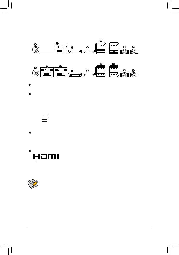
1-5 Back Panel Connectors
GA-H81TN/GA-B85TN/GA-H87TN:

 j
j
GA-Q87TN:
DC Power Connector
Connect the DC power to this port.
RJ-45 LAN Port
The Gigabit Ethernet LAN port provides Internet connection at up to 1 Gbps data rate. The following describes the states of the LAN port LEDs.
Connection/ |
|
|
|
|
|
|
|
|
|
Connection/Speed LED: |
|
Activity LED: |
|
||||||
Speed LED |
|
|
|
|
Activity LED |
|
|
||||||||||||
|
|
|
|
|
|
|
|
|
|||||||||||
|
|
|
|
|
|
|
|
|
|
|
|
|
|
|
State |
Description |
|
State |
Description |
|
|
|
|
|
|
|
|
|
|
|
|
|
|
|
Orange |
1 Gbps data rate |
|
Blinking |
Data transmission or receiving is occurring |
|
|
|
|
|
|
|
|
|
|
|
|
|
|
|
Green |
100 Mbps data rate |
|
Off |
No data transmission or receiving is occurring |
|
|
|
|
|
|
|
|
|
|
|
|
|
|
|
|||||
|
|
|
|
|
|
|
|
|
|
|
|
|
|
|
Off |
10 Mbps data rate |
|
|
|
|
|
|
|
|
|
|
|
|
|
|
|
|
|
|
|
|
|
||
|
|
|
|
LAN Port |
|
|
|
||||||||||||
|
|
|
|
|
|
|
|
|
|||||||||||
DisplayPort
DisplayPort is a digital display interface which is primarily used to connect a video source to a display device such as a computer monitor, though it can also be used to transmit audio, USB, and other forms of data.
HDMI Port
 The HDMI (High-Definition Multimedia Interface) provides an all-digital audio/


 video interface to transmit the uncompressed audio/video signals and is HDCP compliant. Connect the HDMI audio/video device to this port. The HDMI Technology can support a maximum resolution of 4096x2160 but the actual resolutions supported depend on the monitor being used.
•• When After installing the HDMI device, make sure the default device for sound playback is
the HDMI device. (The item name may differ by operating system. Refer the figures below for details.), and enter BIOS Setup, then set Onboard VGA output connect to D-SUB/HDMI under Advanced BIOS Features.
•• Please note the HDMI audio output only supports AC3, DTS and 2-channel-LPCM formats. (AC3 and DTS require the use of an external decoder for decoding.)
MM Only for GA-H81TN.
- 14 -
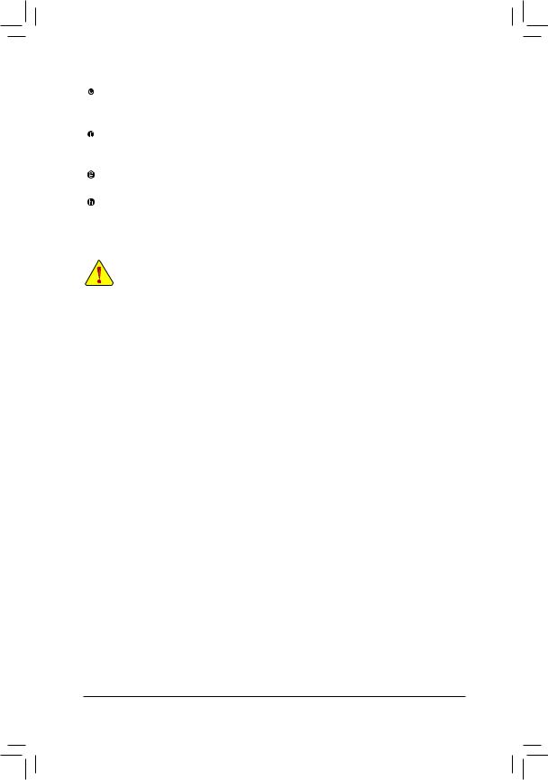
USB 3.0/2.0/1.1 Port
The USB port supports the USB 3.0 specification. Use this port for USB devices such as a USB keyboard/mouse, USB printer, USB flash drive and etc.
Line Out Jack (Green)
The default Line Out (Front Speaker Out) jack. Stereo speakers, earphone or front surroundspeakers can be connected to Line Out (Front Speaker Out) jack.
Mic In Jack (Pink)
The default MIC In jack. Microphone cab be connected to MIC In jack.
USB 2.0/1.1 Port j
The USB port supports the USB 2.0 specification. Use this port for USB devices such as a USB keyboard/mouse, USB printer, USB flash drive and etc.
•• When removing the cable connected to a back panel connector, first remove the cable from your device and then remove it from the motherboard.
•• When removing the cable, pull it straight out from the connector. Do not rock it side to side to prevent an electrical short inside the cable connector.
MM Only for GA-H81TN.
- 15 -
1-6 |
Internal Connectors |
|
|
|
|
|
|
|
|
|
|
|
|
|
|
4 |
|
22 16 |
|
|
6 |
|
|
|
|
|
|
|
11 |
|
|
|
|
|
|
|
|
20 |
|
|
8 |
|
|
|
|
|
|
|
|
|
|
|
|
|
|
|
|
|
|
|
|
|
|
|
|
|
|
|
27 |
|
25 |
|
|
|
|
|
|
|
28 |
|
|
|
|
|
|
|
|
21 |
|
|
7 |
|
|
|
|
|
|
|
|
|
|
|
|
|
|
|
|
|
|
|
26 |
|
|
|
|
|
|
|
|
|
12 |
|
|
|
|
|
|
|
|
|
24 |
|
|
|
|
|
|
|
4 |
|
23 |
|
|
|
|
|
|
|
|
|
13 |
|
|
|
|
|
|
|
5 |
|
|
|
|
|
|
|
|
|
|
|
18 |
|
|
|
|
|
|
|
|
|
1 |
14 |
19 |
2 |
15 |
3 |
10 |
9 |
17 |
1) |
SYS_PANEL |
|
|
|
|
15) |
SYS_FAN |
||
2) |
SATAIII_0 |
|
|
|
|
16) |
DMIC_CON |
||
3) |
SATAIII_1 |
|
|
|
|
17) |
ATX_19V |
||
4) |
SATAIII_2 |
|
|
|
|
18) |
MON_SW |
||
5) |
SATAIII_3 |
|
|
|
|
19) |
SATA_PWR |
||
6) |
FUSB2_2 |
|
|
|
|
20) |
SPKR |
|
|
7) |
FUSB2_3 |
|
|
|
|
21) |
BATTERY |
||
8) |
FUSB2_4 |
|
|
|
|
22) |
CLR_CMOS |
||
9) |
FUSB2_5 |
|
|
|
|
23) |
LCD_VCC |
||
10) |
FUSB3 |
|
|
|
|
24) |
FPD_PWR |
||
11) |
FP_AUDIO |
|
|
|
|
25) |
WF_LED |
||
12) |
FPD |
|
|
|
|
26) |
BL_SW |
|
|
13) |
LVDS |
|
|
|
|
27) |
LPT |
|
|
14) |
CPU_FAN |
|
|
|
|
28) |
COM1 |
|
|
Read the following guidelines before connecting external devices:
•• First make sure your devices are compliant with the connectors you wish to connect.
•• Before installing the devices, be sure to turn off the devices and your computer. Unplug the power cord from the power outlet to prevent damage to the devices.
•• After installing the device and before turning on the computer, make sure the device cable has been securely attached to the connector on the motherboard.
- 16 -
Loading...