


6WMMC7 Series
USER'S MANUAL
1.Support Suspend To RAM Function.
2.Support Hardware Monitor.
3.System power on by PS/2 Mouse: First, enable this function in CMOS Setup, then you can power on the system by double clicking the right or left button of your PS/2 Mouse.
4.System power on by Keyboard: If your ATX power supply supports larger than 300 mA 5V Stand-By current (depends on the specification of keyboards), you can power on your system by entering password from the Keyboard after setting the “Keyboard power on” jumper and password in CMOS Setup.
5.Support 3 steps ACPI LED selectable.
6.Support Modem Ring-On (Include internal Modem and external modem on COM A).
7.Support Wake-up On LAN (Your ATX power supply must support larger than 720 mA 5V Stand-By current).
8.Built-in AC97-Link software audio.
9.Support Audio / Modem Riser (AMR) interface.
10.Support TV/DFP(Digital Flat Panel) function by TV/DFP daughter card (Optional).
11.Aureal AU8810 Hardware Audio (Optional).
Socket 370 Processor MAIN BOARD
REV. 2.1 First Edition
R-21-01-091213

6WMMC7 Series
The author assumes no responsibility for any errors or omissions that may appear in this document nor does it make a commitment to update the information contained herein.
Third-party brands and names are the property of their respective owners.
Dec. 13, 1999 Taipei, Taiwan
1
Quick Installation Guide
I. Quick Installation Guide :
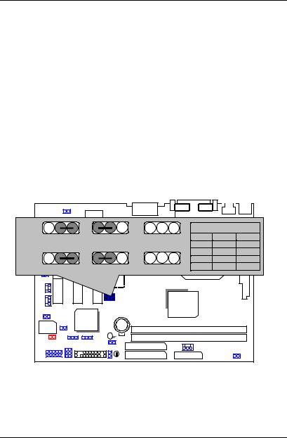
CPU SPEED SETUP
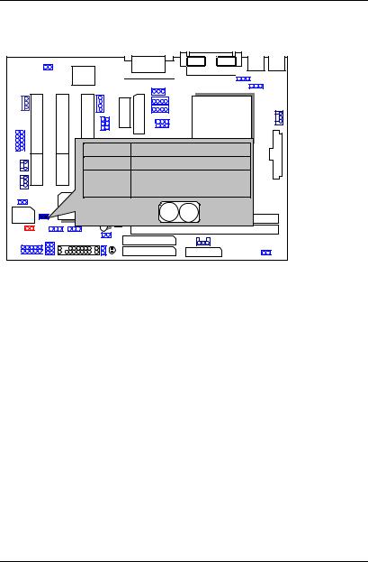
The system bus frequency can be switched at 66MHz / 100MHz / 133MHz and Auto by adjusting JP5,JP23. The CPU ratio is control by BIOS.
0The CPU speed must match with the frequency ratio. It will cause system hanging up if the frequency ratio is higher than that of CPU.
0Note: Please set the CPU host frequency in accordance with your processor’s specifications. We don’t recommend you to set the system bus frequency over the CPU’s specification because these specific bus frequencies are not the standard specifications for CPU, chipset and most of the peripherals. Whether your system can run under these specific bus frequencies properly will depend on your hardware configurations, including CPU, Chipsets, SDRAM, Cards….etc.
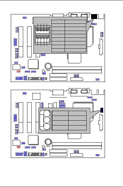
JP5 / JP23 : Set System Bus Speed (See Figure-1)
|
|
AC97 |
|
|
|
|
JP23 1-2 Auto |
1 |
1 |
1 INTEL CPU CLK SET |
|||
|
2-3 66/100 |
133 |
Auto |
JP5 |
JP23 |
|
|
|
|
|
1-2 |
1-2 |
|
JP5 |
1 |
1 |
1 |
66 |
2-3 |
2-3 |
CPU |
NC |
2-3 |
||||
100 |
||||||
1-2 Auto |
|
2-3 66 |
100/133 |
133 |
NC |
NC |
|
|
AU |
|
|
|
|
|
|
8810 |
|
|
|
|
|
|
|
GMCH/ |
|
|
|
|
|
6WMMC7 |
82810/ |
|
|
|
|
|
810E |
|
|
|
|
|
ICH/ |
|
|
|
|
|
FWH32 |
82801 |
|
|
|
|
|
|
|
|
|
|
|
|
Figure-1
Note: JP23 is only available when the motherboard use 82810E chipset.
2

6WMMC7 Series
II. Jumper Setting :
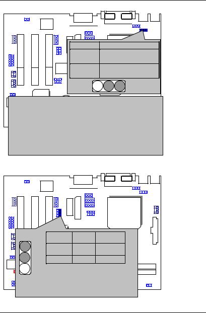
GN : Green Function Switch
AC97 |
|
|
|
|
CPU |
|
AU |
|
|
8810 |
|
|
PIN No. FunctionGMCH/ |
|
|
Open |
Normal Operation |
|
6WMMC7 |
82810 / |
|
810E |
|
ICH/ |
Short |
Entering Green |
|
|
|
82801 |
|
Mode |
FWH32 |
|
|
|
|
|
GD : Green Function LED
|
|
AC97 |
|
|
|
|
|
|
|
|
CPU |
|
|
|
AU |
|
|
|
|
|
8810 |
|
|
|
|
− |
PIN No. Function |
GMCH/ |
|
|
|
82810 |
|||
|
|
1 |
6WMMC7 |
810E |
|
|
1 |
ICH/ |
LED + |
|
|
FWH32 |
82801 |
2 |
LED − |
|
|
+ |
|
||||
|
|
|
|
3 |
|
Quick Installation Guide
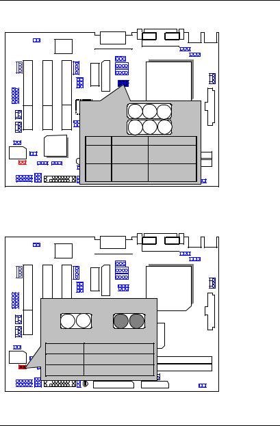
HD : IDE Hard Disk Active LED
|
AC97 |
|
|
|
|
|
|
|
CPU |
|
|
|
AU |
|
|
|
|
8810 |
|
|
|
|
|
GMCH/ |
|
1 |
+ |
PIN No. Function |
|
|
6WMMC7 |
82810 |
||
|
ICH/ |
− |
1 |
LED + |
FWH32 |
82801 |
2 |
LED − |
|
SPKR: External Speaker Connector
AC97 |
|
|
|
|
|
|
|
|
|
CPU |
|
AU |
PIN No. |
Function |
|||
8810 |
|||||
|
|
|
|
||
External Speaker |
1 |
|
VCC |
||
2 |
GMCH/ |
||||
|
6WMMC7 |
82810NC |
|||
+ 182801ICH/ |
|
3 |
|
NC |
|
FWH32 |
|
4 |
|
Data |
|
|
|
|
|
||
4
6WMMC7 Series
J9: Buzzer Enable (Optional)
AC97
CPU
AU |
|
|
8810 |
|
|
PIN No. Function |
|
|
Open |
Internal BuzzerGMCH/ |
Disable |
Close6WMMC7Internal Buzzer82810 Enable
ICH/
FWH32 82801
RES : Reset Switch
AC97
CPU
|
PIN No. Function |
|
|
|
Open |
AU |
|
|
8810 |
|
|
|
Normal |
|
|
|
|
Operation |
GMCH/ |
|
Short |
Reset Hardware |
82810 |
|
|
6WMMC7 |
/810E |
|
ICH/ |
System |
|
|
|
|
|
FWH32 |
82801 |
|
|
|
|
|
|
5
Quick Installation Guide
PWR : Power LED Connector (as 3 steps ACPI LED)
AC97
CPU
|
|
|
AU |
|
|
|
|
8810 |
|
+ |
− |
− |
PIN No. Function |
|
1 |
LED + |
|||
1 |
|
|
|
GMCH/ |
|
|
6WMMC7 |
82810 |
|
|
ICH/ |
|
2 |
LED − |
FWH32 |
82801 |
|
3 |
LED − |
PW: Soft Power Connector
AC97
CPU
AU 8810
PIN No. Function GMCH/ |
|
|
Open |
Normal operation |
|
|
|
6WMMC7 |
82810 |
|
|
|
|
|
|
|
ICH/ |
Short |
Soft On/Off |
|
FWH32 |
82801 |
|||
|
|
|
|
|
6

6WMMC7 Series
IR : Infrared Connector (IR / CIR)
|
AC97 |
|
|
|
PIN |
Function |
|
CPU |
|
No. |
1 |
6 |
||
|
||||
1 |
VCC |
|
|
|
2 |
NCAU |
|
|
|
3 |
IRRX |
|
|
|
|
8810 |
|
|
|
4 |
GND |
|
|
|
5 |
IRTX |
|
GMCH/ |
6 |
NC 6WMMC7 |
82810/ |
7 |
CIRRX |
810E |
|
ICH/ |
VCC |
|
|
|
8 |
5 |
10 |
|
FWH32 |
82801 |
NC |
||
9 |
||||
|
10 |
NC |
|
|
PS/2 Mouse / Keyboard Connector
AC97
|
PS/2 Mouse |
|
PS/2 Mouse/ Keyboard |
|
|
|
|
Pin No. |
Function |
|
|
|
1 |
CPU Data |
6 |
|
5 |
2 |
NC |
8810 |
3 |
GND |
||
|
AU |
|
|
|
4 |
|
3 |
4 |
VCC(+5V) |
|
|
5 |
Clock |
2 |
1 |
GMCH/ |
NC |
6 |
|||
|
6WMMC7 |
82810 |
|
ICH/ PS/2 Keyboard
FWH32 82801
7
Quick Installation Guide
USB : USB Port
|
AC97 |
|
8 |
PIN No. |
Function |
|
|
5 6 7 |
|||||
|
|
|
|
1 |
USB V0 |
|
|
|
|
|
2 |
USB D0- |
|
|
|
|
|
3 |
USB D0+ |
|
|
|
|
|
4 |
GND |
CPU |
|
|
|
|
5 |
USB V1 |
|
|
|
AU |
6 |
USB D1- |
|
|
|
|
7 |
USB D1+ |
|
||
|
1 2 |
8810 |
|
|||
|
3 |
4 |
8 |
GND |
|
|
|
|
|
|
|
||
|
|
|
|
|
GMCH/ |
|
|
|
|
6WMMC7 |
82810/ |
|
|
|
ICH/ |
|
810E |
|
||
|
|
|
|
|
|
|
FWH32 |
82801 |
|
|
|
|
|
|
|
|
|
|
|
|
CPU FAN : CPU Cooling Fan Power Connector
|
AC97 |
|
|
|
1 |
|
CPU |
|
PIN No. Function |
||
|
|
1 |
GND |
|
AU |
2 |
+12V |
|
8810 |
||
|
|
3 |
SENSE |
|
|
|
GMCH/ |
|
6WMMC7 |
82810/ |
|
|
810E |
||
|
ICH/ |
|
|
FWH32 |
82801 |
|
|
|
|
|
|
8
6WMMC7 Series
POWER FAN : Power Cooling Fan Power Connector
|
AC97 |
|
|
|
|
|
CPU |
|
AU |
PIN No. Function |
|
|
8810 |
||
|
|
||
|
6WMMC71 |
1 |
GND |
|
GMCH/ |
+12V |
|
|
82810 |
||
|
ICH/ |
3 |
SENSE |
|
82801 |
||
FWH32 |
|
|
|
|
|
|
|
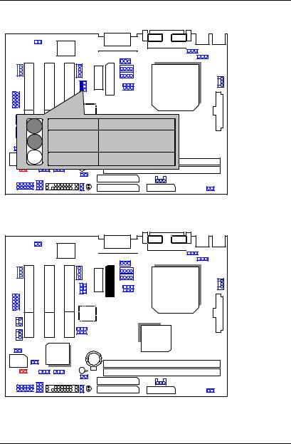
SYSTEM FAN : System Cooling Fan Power Connector
AC97
CPU
|
AU |
|
|
|
8810 |
|
|
1 |
PIN No. Function |
|
|
|
1 |
GND |
GMCH/ |
|
|
|
|
|
2 |
+12V |
82810/ |
|
810E |
||
|
|
6WMMC7 |
|
|
ICH/ |
3 |
SENSE |
FWH32 |
82801 |
||
|
|
|
9

Quick Installation Guide
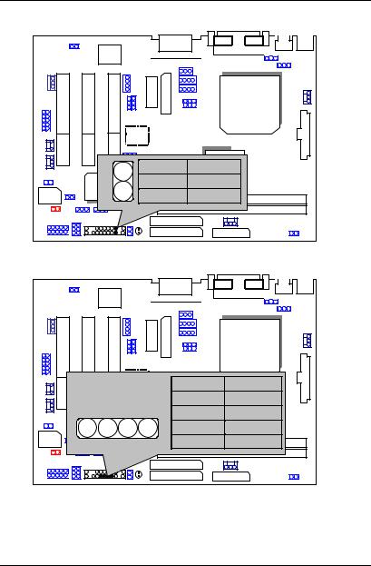
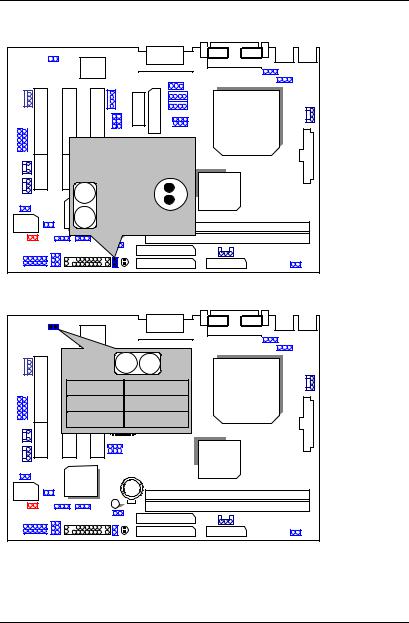
IDE1: Primary IDE Port
AC97
CPU
AU |
8810 |
|
|
|
|
GMCH/ |
|
|
|
|
|
|
|
|
6WMMC7 |
82810/ |
|
|
|
810E |
ICH/
FWH32 82801
1 
IDE2: Secondary IDE Port
AC97
CPU
AU |
8810 |
|
|
|
|
GMCH/ |
|
|
|
|
|
|
|
|
6WMMC7 |
82810/ |
|
|
|
||
|
|
|
810E |
ICH/
FWH32 82801
 1
1
10

6WMMC7 Series
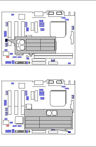
FLOPPY : Floppy Port
AC97
CPU
AU |
8810 |
|
|
|
|
GMCH/ |
|
|
|
|
|
|
|
|
6WMMC7 |
82810/ |
|
|
|
||
|
|
|
810E |
ICH/
FWH32 82801
1
ATX POWER : ATX Power Connector
|
AC97 |
|
1 |
|
|
|
|
|
|
|
|
|
|
|
11 |
|
|
|
|
Pin No. |
Function |
CPU |
|
|
|
3,5,7,13, |
GND |
||
|
|
|
|||
|
|
15-17 |
|
|
|
|
|
AU |
|
3.3V |
|
|
|
1,2,118810 |
|
||
|
|
4,6,19,20 |
VCC |
|
|
|
|
10 |
|
+12V |
GMCH/ |
|
|
12 |
|
-12V |
82810/ |
|
|
18 |
6WMMC7 |
810E |
|
|
ICH/ |
|
-5V |
|
|
FWH32 |
82801 |
8 |
|
Power Good |
|
|
|
||||
|
|
9 |
|
5V SB stand by+5V |
|
|
|
14 |
|
PS-ON(Soft On/Off) |
|
11

Quick Installation Guide
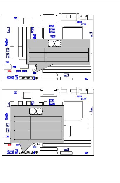
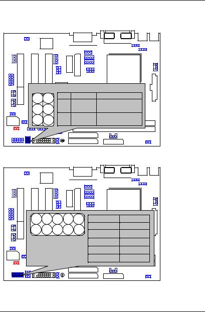
COM A / LPT Port
LPTAC97PORT
COM A
CPU
AU |
8810 |
|
GMCH/ |
|
6WMMC7 |
82810/ |
|
810E |
||
ICH/ |
||
|
FWH32 82801
VGA : VGA Port
AC97
CPU
AU |
8810 |
|
|
|
|
GMCH/ |
|
|
|
|
|
|
|
|
6WMMC7 |
82810/ |
|
|
|
||
|
|
|
810E |
ICH/
FWH32 82801
12
6WMMC7 Series
JP12:Clear CMOS Function
|
AC97 |
|
|
|
|
|
|
|
|
|
CPU |
|
|
|
3 |
2 |
1 |
|
|
AU |
|
|
|
|
|
8810 |
|
|
|
|
|
PIN No. |
|
|
Function |
|
|
1-2 close |
|
|
GMCH/ |
|
|
Clear CMOS |
|||
|
|
6WMMC7 |
|
|
82810 |
|
ICH/ |
2-3 close |
Normal (Default) |
||
|
|
|
|
|
|
FWH32 |
82801 |
|
|
|
|
|
|
|
|
|
|
JP2: PS/2 Keyboard Power On Selection
|
AC97 |
|
|
|
|
|
|
|
3 |
2 |
1 |
|
|
|
|
|
CPU |
|
PIN No. Function |
||||
|
|
AU |
PS/2 Keyboard Power |
||
|
|
8810 |
|||
|
|
1-2 |
|||
|
|
close |
on Enabled |
||
|
|
2-3 |
|
|
GMCH/ |
|
|
|
|
82810/ |
|
|
|
PS/2 Keyboard Power |
|||
|
|
close |
6WMMC7 |
|
810E |
|
ICH/ |
on Disabled (Default) |
|||
FWH32 |
82801 |
|
|
|
|
|
|
|
|
|
|
13

Quick Installation Guide
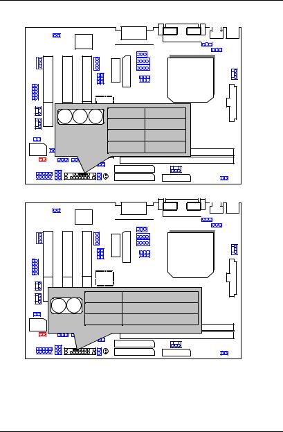
J8:Game & Audio Port
AC97
CPU
|
AU |
|
|
|
8810 |
|
|
|
Line Out |
|
GAME |
|
|
GMCH/ |
|
|
|
MIC |
|
|
6WMMC7 Line In |
82810/ |
|
|
810E |
||
|
ICH/ |
|
|
FWH32 |
82801 |
|
|
|
|
|
|
J7:CD Audio Line In
AC97
|
|
|
CPU |
|
|
AU |
1 |
|
|
8810 |
|
|
|
|
|
|
|
PIN No. |
Function |
|
|
1 |
GMCH/ |
|
|
82810/ |
|
|
|
CD_L |
|
|
|
6WMMC7 |
810E |
|
ICH/ |
2,3 |
GND |
FWH32 |
82801 |
4 |
CD_R |
|
|||
|
|
14
6WMMC7 Series
JP11:AUX_IN |
|
|
|
|
|
AC97 |
JP11 |
|
|
|
|
|
|
|
|
|
|
PIN No. |
Function |
|
|
|
1 |
AUX_L |
|
|
|
2,3 |
CPU |
|
|
|
GND |
|
|
AU |
1 |
4 |
AUX_R |
|
8810 |
|||
|
|
|
|
|
|
|
|
GMCH/ |
|
|
|
6WMMC7 |
82810/ |
|
|
ICH/ |
810E |
|
|
|
|
|
|
|
FWH32 |
82801 |
|
|
|
|
|
|
|
|
JP3 TEL :The connector is for Modem with internal voice connector.
AC97
CPU
AU |
8810 |
1
TEL
|
|
PIN No. |
Function |
|
|
|
|
|
GMCH/ |
|
|
6WMMC7 |
|
82810/ |
|
|
1 |
Phone-in |
|
|
ICH/ |
|
|
810E |
|
|
2,3 |
GND |
|
FWH32 |
82801 |
|
||
|
|
|
4 |
Mono-out |
15
Quick Installation Guide
JP18 SPDIF:(Optional for the SPDIF output is capable of providing digital audio to external speakers or compressed AC3 data to an external Dobly Digital decoder.)
|
AC97 |
|
|
|
|
1 |
CPU |
|
AU |
PIN No. |
Function |
|
1 |
VCC |
|
|
8810 |
||
|
|
||
|
|
2 |
SPDIF OUT |
|
|
3 |
GMCH/ |
|
|
82810/ |
|
|
|
GND |
|
|
ICH/ |
6WMMC7 |
810E |
|
|
||
|
|
|
|
FWH32 |
82801 |
|
|
|
|
|
J14 : Wake on LAN
AC97
1 |
PIN No. |
Function |
|
|
2 |
1 |
+5V SB |
|
|
2 |
GND |
|
||
3 |
CPU |
|||
3 |
Signal |
|||
|
AU |
8810 |
GMCH/
6WMMC7 |
82810/ |
810E |
ICH/
FWH32 82801
16
6WMMC7 Series
J17 RING PWR ON: Internal Modem Card Ring Pwr On
|
AC97 |
|
|
|
|
|
|
|
CPU |
|
|
AU |
|
|
|
|
8810 |
|
|
|
|
PIN No. |
Function |
|
|
|
1 |
|
GMCH/ |
|
ICH/ 1 |
Signal82810/ |
||
|
6WMMC7 |
GND |
810E |
|
|
2 |
|
||
FWH32 |
82801 |
|
|
|
|
|
|
|
|
JP1 : STR Function
(If you want to use STR Function, please set jumper JP1 Closed.)
|
AC97 |
|
|
|
|
|
CPU |
|
|
AU |
|
|
|
8810 |
|
|
|
6WMMC7 |
GMCH/82810/1 |
|
|
810E |
|
|
ICH/ |
PIN No. |
Function |
FWH32 |
82801 |
Close |
STR Enable |
|
|||
|
|
Open |
STR Disable(Default) |
|
|
|
17 |
Quick Installation Guide
JP10 : STR LED Connector & DIMM LED
|
AC97 |
|
|
|
|
|
|
|
CPU |
|
STR LEDAUConnector |
|
||
|
External.8810 |
|
|
|
|
1 |
|
+ |
GMCH/ |
|
|
82810/ |
||
|
JP10 |
6WMMC7 |
810E |
|
|
ICH/ |
|||
|
DIMM LED |
|
||
FWH32 |
82801 |
|
|
|
|
|
|
|
|
JP14 : Case Open
AC97 |
|
|
|
JP14 |
|
1 |
|
PIN No. |
Function |
CPU |
|
1 |
|
Signal |
|
2 |
|
AUGND |
|
|
8810 |
|
|
|
|
|
|
GMCH/ |
|
|
|
|
|
|
|
|
|
|
|
|
|
|
|
|
|
|
|
|
|
|
|
6WMMC7 |
82810/ |
|
|
|
810E |
ICH/
FWH32 82801
18
6WMMC7 Series
JP16: Top Block Lock
|
AC97 |
|
|
|
PIN No. |
Function |
CPU |
|
|
||
|
Open |
Top Block Lock |
|
|
Close |
AU |
|
|
8810 |
|
|
|
Top Block Unlock |
|
|
|
|
(Default) |
GMCH/ |
|
|
6WMMC7 |
82810/ |
|
ICH/ |
810E |
|
|
|
|
|
FWH32 |
82801 |
|
|
|
|
|
JP13 :Safe mode/Recovery/Normal |
|||
|
AC97 |
|
|
|
|
|
CPU |
|
|
AU |
|
|
|
8810 |
|
|
|
|
1 |
|
|
|
GMCH/ |
|
|
PIN No. |
82810/ |
|
|
Function |
|
|
ICH/ |
6WMMC7 |
810E |
|
1-2close |
Normal (Default) |
|
FWH32 |
82801 |
||
|
2-3close |
Safe mode |
|
|
|
||
|
|
1-2-3open |
Recovery |
19
Quick Installation Guide
JP17: Onboard Sound Function (Optional)
AC97
CPU
|
AU |
|
|
|
8810 |
|
|
1 |
PIN No. |
Function |
|
1-2close |
|
GMCH/ |
|
|
Enabled Sound82810/ |
||
|
ICH/ |
6WMMC7 |
810E |
|
(Default) |
|
|
FWH32 |
82801 |
Disabled Sound |
|
2-3close |
|||
TV/DFP :TV-Out / Digital Flat Panel Daughter Card
Connector(Optional).
|
AC97 |
|
|
1 |
|
|
|
CPU |
|
AU |
|
|
8810 |
|
|
|
GMCH/ |
|
6WMMC7 |
82810/ |
|
810E |
|
|
ICH/ |
|
FWH32 |
82801 |
|
|
|
|
|
|
20 |
6WMMC7 Series
J13/J20 : USB Port Selection (Optional)
|
AC97 |
|
|
|
|
|
|
|
|
|
CPU |
|
J13 J20 |
AU |
|
|
|
|
8810 |
PIN No. |
Function |
||
|
1 |
1 |
|
||
|
J13 |
1-2close |
Front Panel USB |
||
|
|
|
|
|
GMCH/ |
|
|
|
J206WMMC71-2close Enable |
||
|
|
|
J13 |
2-3close |
82810 |
|
ICH/ |
|
Back Panel USB |
||
|
|
|
|
|
|
FWH32 |
82801 |
|
J20 |
2-3close |
Enable |
|
|
||||
J19 : Front Panel USB Port (Optional)
|
AC97 |
|
|
|
|
|
|
|
|
|
|
|
CPU |
|
9 |
AU |
1 |
PIN No. |
Function |
|
|
|
8810 |
|
1,4,5,10 |
NC |
|
|
10 |
|
2 |
|||
|
|
2 |
GMCH/ |
+5V |
||
|
|
|
|
|||
|
|
|
6WMMC7 |
3,7,9 |
82810/ |
GND |
|
ICH/ |
|
810E |
|||
|
|
|
6 |
|
USBP0+ |
|
|
82801 |
|
|
|
||
FWH32 |
|
|
8 |
|
USBP0- |
|
|
|
|
|
|||
|
|
|
|
|
||
|
|
|
|
21 |
|
|
Quick Installation Guide
JP15: Timeout Reboot Function
|
AC97 |
|
|
|
|
|
CPU |
|
AU |
Function |
|
|
PIN No. |
|
|
|
8810 |
Timeout Reboot |
|
|
Open |
||
|
Close |
|
GMCH/ |
|
No Reboot on Timeout |
||
|
|
(Default) |
82810/ |
|
6WMMC7 |
810E |
|
|
ICH/ |
JP15 |
1 |
FWH32 |
82801 |
||
|
|||
JP19: USB Device Wake-up Function
22
6WMMC7 Series
AC97 |
|
|
|
|
PIN No. |
Function |
|
|
1-2 close |
CPU |
|
|
Disable USB Device |
||
|
|
Wake-up (Default) |
|
AU |
2-3 close |
Enable USB Device |
|
8810 |
|||
|
|
Wake-up |
|
|
JP19 |
GMCH/ |
1 |
|
82810 |
||
ICH/ |
6WMMC7 |
|
|
|
|
|
|
(If you want82801to use “USB KB/Mouse Wake from S3”
FWH32
function, you have to set the BIOS setting “USB KB/Mouse Wake from S3” enabled, and the jumper “JP19” enabled).
*(Power on the computer and as soon as memory counting starts, press <Del>. You will enter BIOS Setup. Select the item “POWER MANAGEMENT SETUP”, then select “USB KB/Mouse Wake from S3: Enabled”. Remember to save
the setting by pressing "ESC" and choose the “SAVE & EXIT SETUP” option.)
JP22 : AMR Function Select (Optional)
AC97
CPU
|
AU |
|
|
JP22 |
8810 |
|
|
PIN No. |
Onboard |
AMR Card |
|
1 |
1-2 close |
CODEC |
Secondary |
Primary |
|||
|
6WMMC7 |
GMCH/ |
|
|
(Default) |
||
|
|
|
82810 |
ICH/ |
2-3 close |
Disabled |
Primary |
FWH32 |
82801 |
|
Note: |
||
|
||
|
If you use software audio(onboard CODEC only), |
|
|
your modem riser must be “Secondary”. |
|
|
If you don’t use onboard software audio, your |
|
|
audio/modem riser must be “Primary”. |
23
Quick Installation Guide
JP20/JP21:Quad Speaker (Optional)
AC97
CPU
AU |
|
2 |
1 |
8810 |
3 |
||
JP20 |
|
JP21 |
3 |
2 |
|
1 |
|
|
|
GMCH/ |
|
|
|
6WMMC7 |
|
82810 |
Function |
|
ICH/ |
PIN No. |
|
|||
FWH32 |
82801 |
JP20 |
1-2close LINE_IN |
|
|
|
JP21 |
1-2close |
|
|
|
JP20 |
2-3close |
QUAD OUT |
|
|
JP21 |
2-3close |
|
JP24: FWH Write Protection
AC97
CPU
JP24 |
AU |
|
8810 |
|
Open |
|
GMCH/ |
|
|
Close82810/ |
|||
|
PIN No. |
6WMMC7 |
|
810E |
|
Function |
|
||
|
ICH/ |
|
|
|
|
82801 |
Normal(Default) |
||
FWH32 |
Open |
|||
|
|
|
|
|
|
Close |
Write Protection |
||
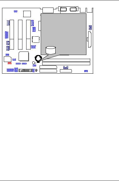
BAT1: Battery
24
6WMMC7 Series
AC97
AU 8810
Danger of explosion if battery is incorrectly replaced.
Replace only with the same or equivalent type recommendedCPU by the manufacturer.
Dispose of used batteries according to the manufacturer’s instructions.
+ GMCH/
6WMMC7 82810
ICH/
FWH32 82801
25

Quick Installation Guide
III. Top Performance Test Setting:
The following performance data list is the testing results of some popular benchmark testing programs.
Users have to modify the value for each item in chipset features as follow for top performance setting.
CMOS Setup Utility-Copyright( C ) 1984-1999 Award Software
Advanced Chipset Features
|
SDRAM CAS Latency Time |
2 |
Item Help |
|
SDRAM Cycle Time Tras/Trc |
5/7 |
|
|
SDRAM RAS-to-CAS Delay |
2 |
Menu Level |
|
SDRAM RAS Precharge Time |
2 |
|
|
SDRAM Buffer Strength |
Auto |
|
|
DRAM Page Closing Policy |
Precharge Bank |
|
|
System BIOS Cacheable |
Enabled |
|
|
Video BIOS Cacheable |
Enabled |
|
|
Delayed Transaction |
Disabled |
|
|
On-Chip Video Window Size |
64MB |
|
|
Local Memory Frequency |
100 MHz |
|
|
* Onboard Display Cache Setting * |
|
|
|
Initial Display Cache |
Enabled |
|
|
Display Cache Timing |
Fast |
|
|
|
|
|
|
↑↓→ ← Move Enter:Select +/-/PU/PD:Value |
F10:Save ESC:Exit |
F1:General Help |
F5:Previous Values F6:Fail-Safe Defaults F7:Optimized Defaults
*The above settings have to modify according to different kinds of CPU, SDRAM, and peripherals for your system to work properly.
26

6WMMC7 Series
These data are just referred by users, and there is no responsibility for different testing data values gotten by users. (The different Hardware & Software configuration will result in different benchmark testing results.)
• CPU |
Intel CeleronTM 466MHz Socket 370 processor |
• DRAM |
(128x 1) MB SDRAM (SEC KM48S8030CT-GA) |
• CACHE SIZE |
128 KB included in CPU |
• DISPLAY |
Onboard Intel Corporation 810 Graphics Controller Hub) |
• STORAGE |
Onboard IDE (IBM DTNA-371800) |
• O.S. |
Windows NT™ 4.0 SPK5 |
• DRIVER |
Display Driver at 1024 x 768 x 64k colors x 75Hz. |
Processor |
350MHz (100x3.5) |
500MHz |
|
(66x7.5) |
|||
|
|
||
|
|
|
|
Winbench99 (Ver1.1) |
|
|
|
CPU mark99 |
30 |
37.2 |
|
FPU Winmark |
1880 |
2680 |
|
Business Disk |
3380 |
3140 |
|
Hi-End Disk |
5890 |
5350 |
|
Business Graphics |
125 |
139 |
|
Hi-End Graphics |
286 |
364 |
|
Winstone99 (Ver1.0) |
|
|
|
Business |
24.8 |
27.2 |
|
Hi-End |
19.7 |
21.9 |
27
 Loading...