


 Loading...
GA-6LXSG
GA-6LXSL
LGA1150 socket motherboard for Intel® E3 series processors
User's Manual
Rev. 1001

Copyright
© 2013 GIGA-BYTE TECHNOLOGY CO., LTD. All rights reserved.
The trademarks mentioned in this manual are legally registered to their respective owners.
Disclaimer
Information in this manual is protected by copyright laws and is the property of GIGABYTE. Changes to the specifications and features in this manual may be made by GIGABYTE without prior notice. No part of this manual may be reproduced, copied, translated, transmitted, or published in any form or by any means without GIGABYTE's prior written permission.
Documentation Classifications
In order to assist in the use of this product, GIGABYTE provides the following types of documentations:
For detailed product information, carefully read the User's Manual.
For product-related information, check on our website at:
http://www.gigabyte.com

Table of Contents
Box Contents.................................................................................................................... |
|
|
5 |
GA-6LXSG/GA-6LXSL Motherboard Layout.................................................................... |
6 |
||
GA-6LXSG Block Diagram............................................................................................... |
9 |
||
GA-6LXSL Block Diagram.............................................................................................. |
10 |
||
Chapter 1 Hardware Installation.................................................................................... |
11 |
||
1-1 |
Installation Precautions................................................................................... |
11 |
|
1-2 |
Product Specifications.................................................................................... |
12 |
|
1-3 Installing the CPU and CPU Cooler................................................................ |
14 |
||
|
1-3-1 |
Installing the CPU................................................................................................... |
14 |
|
1-3-2 |
Installing the CPU Cooler........................................................................................ |
16 |
1-4 |
Installing the Memory...................................................................................... |
17 |
|
|
1-4-1 |
Dual Channel Memory Configuration...................................................................... |
17 |
|
1-4-2 |
Installing a Memory ................................................................................................ |
18 |
1-5 |
Back Panel Connectors.................................................................................. |
19 |
|
1-6 |
Internal Connectors........................................................................................ |
21 |
|
Chapter 2 BIOS Setup................................................................................................... |
36 |
||
2-1 |
The Main Menu............................................................................................... |
38 |
|
2-2 |
Advanced Menu.............................................................................................. |
40 |
|
|
2-2-1 |
ACPI Configuration................................................................................................. |
41 |
|
2-2-2 |
Trusted Computing (Optional)................................................................................. |
42 |
|
2-2-3 |
PCI Subsystem Settings......................................................................................... |
43 |
|
2-2-3-1 |
PCI Express Settings.............................................................................................. |
45 |
|
2-2-4 |
CPU Configuration.................................................................................................. |
47 |
|
2-2-5 |
SATA Configuration................................................................................................. |
51 |
|
2-2-5-1 |
Software Feature Mask Configuration..................................................................... |
53 |
|
2-2-6 |
Info Report Configuration........................................................................................ |
55 |
|
2-2-7 |
USB Configuration.................................................................................................. |
56 |
|
2-2-8 |
IT8732 Super IO Configuration............................................................................... |
57 |
|
2-2-9 |
IT8732 HW Monitor ................................................................................................ |
59 |
|
2-2-10 |
Serial Port Console Redirection.............................................................................. |
60 |
|
2-2-11 |
Network Stack......................................................................................................... |
63 |
|
2-2-12 |
Intel(R) Anti-Theft Technology Configuration.......................................................... |
64 |
|
2-2-13 |
Switchable Graphics............................................................................................... |
65 |
|
2-2-14 |
Intel(R) Rapid Start Technology.............................................................................. |
66 |
|
2-2-15 |
PCH-FW Configuration........................................................................................... |
67 |
|
2-2-16 |
Intel(R) Smart Connect Technology........................................................................ |
69 |
|
|
|
|
|
|
- 3 - |
|

|
2-2-17 |
Smart Settings......................................................................................................... |
70 |
|
2-2-18 |
AMT Configuration.................................................................................................. |
71 |
|
2-2-19 |
Acoustic Management Configuration...................................................................... |
73 |
2-3 |
Chipset Menu.................................................................................................. |
74 |
|
|
2-3-1 |
System Agent (SA)Configuration............................................................................ |
75 |
|
2-3-1-1 |
Graphic Configuration............................................................................................. |
76 |
|
2-3-1-2 |
NB PCIe Configuration............................................................................................ |
78 |
|
2-3-1-3 |
Memory Configuration............................................................................................. |
80 |
|
2-3-2 |
PCH-IO Configuration............................................................................................. |
82 |
|
2-3-2-1 |
PCI Express Configuration...................................................................................... |
84 |
|
2-3-2-2 |
USB Configuration.................................................................................................. |
85 |
2-4 |
Security Menu................................................................................................. |
86 |
|
|
2-4-1 |
Secure Boot menu ................................................................................................. |
87 |
|
2-4-1-1 |
Key Management .................................................................................................. |
88 |
2-5 |
Boot Menu...................................................................................................... |
90 |
|
|
2-5-1 |
CSM16 Parameters ................................................................................................ |
92 |
|
2-5-2 |
CSM Parameters .................................................................................................... |
93 |
2-6 |
Exit Menu........................................................................................................ |
95 |
|
2-7 |
BIOS Beep Codes.......................................................................................... |
96 |
|
2-8 |
BIOS Recovery Instruction............................................................................. |
97 |
|
Chapter 3 Appendix |
....................................................................................................... |
98 |
|
3-1 |
Regulatory Statements................................................................................... |
98 |
|
- 4 -
Box Contents
GA-6LXSG/GA-6LXSL motherboard
Driver CD
Two SATA cables
I/O Shield
•The box contents above are for reference only and the actual items shall depend on the product package you obtain. The box contents are subject to change without notice.
•The motherboard image is for reference only.
- 5 -
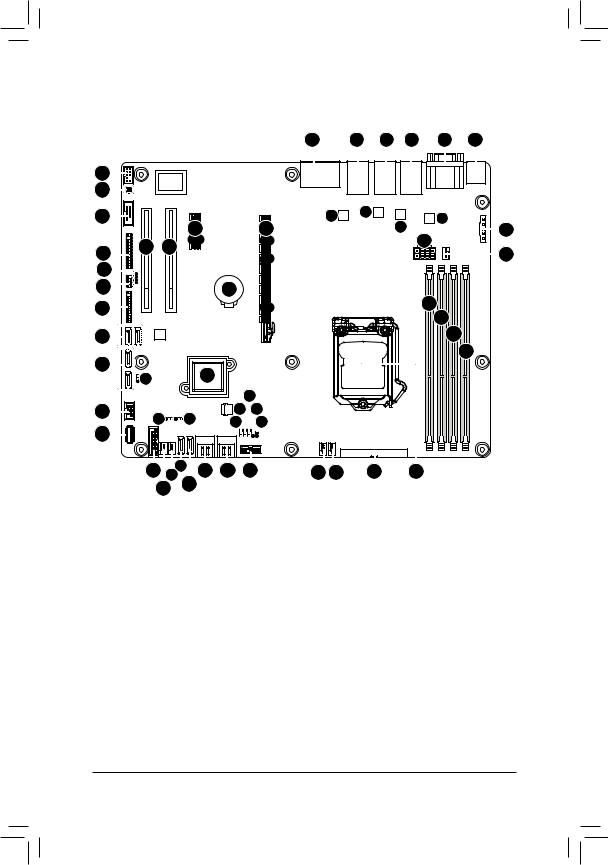
GA-6LXSG/GA-6LXSL Motherboard Layout |
|
|
|
||||||||||
|
|
|
|
|
|
|
|
1 |
2 |
3 |
4 |
5 |
6 |
45 |
|
|
|
|
|
|
|
|
|
|
|
|
|
44 |
|
|
|
|
|
|
|
|
|
|
|
|
|
43 |
|
|
|
|
|
|
|
51 |
|
52 |
|
54 |
|
|
|
48 |
|
|
50 |
|
53 |
|
7 |
||||
|
|
|
|
|
|
|
9 |
|
|||||
|
|
|
|
|
|
|
|
|
|||||
42 |
46 |
47 |
|
|
|
|
|
|
|
|
|
8 |
|
|
|
|
|
|
|
|
|
|
|
||||
|
|
|
|
|
|
|
|
|
|
|
|
||
41 |
|
|
|
|
|
|
|
|
|
|
|
|
|
40 |
|
|
|
|
49 |
|
|
|
|
|
10 |
|
|
39 |
|
|
|
|
|
|
|
|
|
|
11 |
|
|
|
|
|
|
|
|
|
|
|
|
|
|
||
|
|
|
|
|
|
|
|
|
|
|
|
|
|
38 |
|
|
|
|
|
|
|
|
|
|
|
12 |
|
37 |
|
|
|
|
|
|
|
|
|
|
|
13 |
|
|
|
|
35 |
|
|
|
|
|
|
|
|
|
|
|
36 |
|
|
|
|
|
|
|
|
|
|
|
|
|
|
|
|
|
|
20 |
|
|
|
|
|
|
|
34 |
29 |
28 |
|
21 |
19 |
|
|
|
|
|
|
||
33 |
|
22 |
|
18 |
|
|
|
|
|
|
|||
|
|
|
|
|
|
|
|
|
|
|
|
|
|
|
32 |
3027 |
25 |
24 |
23 |
17 16 |
|
15 |
14 |
|
|
||
|
31 |
26 |
|
|
|
|
|
|
|
|
|
|
|
- 6 -

Item |
Code |
Description |
|
1 |
HD_AUDIO |
Audio jacks |
|
2 |
USB3_LAN1 |
LAN1 port (top) / USB 3.0 ports (bottom) |
|
3 |
USB2_LAN2 |
LAN2 port (top) / USB 2.0 ports (bottom) |
|
4 |
LAN3_4 |
LAN ports |
|
5 |
VGA_COM1 |
Serial port (top) / VGA port (bottom) |
|
6 |
PS2_USB2 |
USB 2.0 ports (top)/PS/2 connector |
|
(buttom) |
|||
|
|
||
7 |
PMBUS |
PMBus connector |
|
8 |
CPU0_FAN |
CPU fan connector |
|
9 |
P12V_AUX1 |
8 pin power connector |
|
10 |
DDR3_P0_A0 |
DIMM slot (channel 1 slot 0 ) |
|
11 |
DDR3_P0_A1 |
DIMM slot (channel 1 slot 1 ) |
|
12 |
DDR3_P0_B0 |
DIMM slot (channel 2 slot 0 ) |
|
13 |
DDR3_P0_B1 |
DIMM slot (channel 2 slot 1 ) |
|
14 |
CPU0 |
Intel LGA1150 socket |
|
15 |
ATX1 |
24 pin main power connector |
|
16 |
SYS_FAN4 |
System fan connector#4 |
|
17 |
SYS_FAN3 |
System fan connector#3 |
|
18 |
CASE_OPEN |
Case open intrusion header |
|
19 |
BIOS_RCVR |
BIOS recovery jumper |
|
20 |
CLR_CMOS |
Clear CMOS jumper |
|
21 |
PCH_ME |
ME recovery jumper |
|
22 |
BIOS_PWD |
Clearing supervisor password jumper |
|
23 |
TPM |
TPM module connector |
|
24 |
SATA_4_5 |
SATA 6Gb/s connectors |
|
25 |
SATA_2_3 |
SATA 6Gb/s connectors |
|
26 |
SATA1 |
SATA 6Gb/s connector |
|
27 |
SATA0 |
SATA 6Gb/s connector |
|
28 |
SATA_DOM1 |
SATA port 1 DOM support jumper |
|
29 |
SATA_DOM0 |
SATA port 0 DOM support jumper |
|
30 |
SYS_FAN2 |
System fan connector#2 |
|
31 |
SYS_FAN1 |
System fan connector#1 |
|
32 |
F_USB3 |
USB 3.0 header |
|
33 |
USB2_A1 |
USB 2.0 Type A connector |
|
34 |
F_USB2 |
USB 2.0 header |
|
35 |
U3 |
Intel H87 Express chipset |
|
36 |
ME_UPDATE |
ME Update jumper |
- 7 -
37SATA6/7
38SATA8/9
39BP_1
40SATA_SGP1
41LAN3_ACT/LAN4_ACT
42FP_1
43COM1
44SPDIF_IN1/SPDIF_OUT1
45F_AUDIO
46PCI_1
47PCI_2
48PCIE_1
49BAT
50PCIE_4
51U615(I210)/U604(RTL8111F)
52U617(I210)/U605 (RTL8111F)
53U619(I210)/U606(RTL8111F)
54U621(I210)/U607(RTL8111F)
SATA 6Gb/s connectors
SATA 6Gb/s connectors Back plane board header SGPIO header
LAN3 Active LED (Bottom)
LAN4 Active LED (Upper) Front panel header
Serial port cable connector SPDIF In header (Upper)
SPDIF Out header (Bottom) Front audio header
PCI 32bit/33MHz slot PCI 32bit/33MHz slot PCI-E x1 slot Battery socket PCI-E x16 slot
Intel I210 GbE LAN chipset (GA-6LXSG)
Realtek RTL8111F GbE LAN chipset (GA-6LXSL) Intel I210 GbE LAN chipset (GA-6LXSG)
Realtek RTL8111F GbE LAN chipset (GA-6LXSL) Intel I210 GbE LAN chipset (GA-6LXSG)
Realtek RTL8111F GbE LAN chipset (GA-6LXSL) Intel I210 GbE LAN chipset (GA-6LXSG)
Realtek RTL8111F GbE LAN chipset (GA-6LXSL)
CAUTION! If a SATA type hard drive is connected to the motherboard, please ensure the jumper is closed and set to 2-3 pins (Default setting), in order to reduce any risk of hard disk damage. Please refer to Page 35 for SATA_DOM0 and SATA_DOM1 jumper setting instruction.
- 8 -
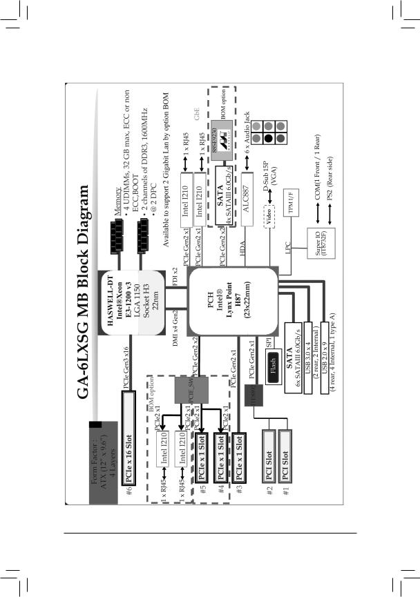
GA-6LXSG Block Diagram
- 9 -

GA-6LXSL Block Diagram
- 10 -
Chapter 1 Hardware Installation
1-1 Installation Precautions
The motherboard contains numerous delicate electronic circuits and components which can become damaged as a result of electrostatic discharge (ESD). Prior to installation, carefully read the user's manual and follow these procedures:
•Prior to installation, do not remove or break motherboard S/N (Serial Number) sticker or warranty sticker provided by your dealer. These stickers are required for warranty validation.
•Always remove the AC power by unplugging the power cord from the power outlet before installing or removing the motherboard or other hardware components.
•When connecting hardware components to the internal connectors on the motherboard, make sure they are connected tightly and securely.
•When handling the motherboard, avoid touching any metal leads or connectors.
•It is best to wear an electrostatic discharge (ESD) wrist strap when handling electronic components such as a motherboard, CPU or memory. If you do not have an ESD wrist strap, keep your hands dry and first touch a metal object to eliminate static electricity.
•Prior to installing the motherboard, please have it on top of an antistatic pad or within an electrostatic shielding container.
•Before unplugging the power supply cable from the motherboard, make sure the power supply has been turned off.
•Before turning on the power, make sure the power supply voltage has been set according to the local voltage standard.
•Before using the product, please verify that all cables and power connectors of your hardware components are connected.
•To prevent damage to the motherboard, do not allow screws to come in contact with the motherboard circuit or its components.
•Make sure there are no leftover screws or metal components placed on the motherboard or within the computer casing.
•Do not place the computer system on an uneven surface.
•Do not place the computer system in a high-temperature environment.
•Turning on the computer power during the installation process can lead to damage to system components as well as physical harm to the user.
•If you are uncertain about any installation steps or have a problem related to the use of the product, please consult a certified computer technician.
- 11 - |
Hardware Installation |
1-2 |
Product Specifications |
||
|
|
|
|
|
CPU |
|
Support for Intel® Xeon® E3-1200 V3 family processors in the LGA1150 package |
|
|
|
L3 cache varies with CPU |
|
Chipset |
|
Intel® H87 Express chipset |
|
Memory |
|
4 x 1.5V DDR3 DIMM sockets supporting up to 32 GB of system memory |
|
|
|
Dual channel memory architecture |
|
|
|
Support for DDR3 1333/1600 MHz memory modules |
|
|
|
Support for non-ECC, un-buffered memory modules |
|
LAN |
|
4 x Intel® I210 supports 10/100/1000 Mbps (GA-6LXSG) |
|
|
|
4 x Realtek® 8111F-VB supports 10/100/1000 Mbps (GA-6LXSL) |
|
Onboard |
|
Build-In Intel® H87 Express chipset |
|
Graphics |
|
|
|
Onboard Audio |
|
Realtek® ALC887 high definition audio controller |
|
|
|
|
|
Storage Interface |
10 x SATA 6Gb/s connectors |
|
|
|
|
6 x SATA 6Gb/s connectors via Intel® H87 chipset supports for Intel RST SATA |
|
|
|
RAID 0,1,10,5 |
|
|
|
4 x SATA 6Gb/s connectors via Marvell® 88SE9230 chipset supports for RAID 0/1/10 |
|
USB |
|
Up to 7 USB 2.0 ports (4 on the back panel, 1 Type A connector, 2 via the USB |
|
|
|
brackets connected to the internal USB headers) |
|
|
|
Up to 4 USB 3.0 ports (2 on the back panel, 2 via the USB brackets connected |
|
|
|
to the internal USB headers) |
|
Expansion Slots |
|
1 x PCIe x16 slot (Gen3 x16 bus) |
|
|
|
1 x PCIe x1 slot (Gen2 x1 bus) |
|
|
|
2 x PCI 32bit/33MHz slots |
|
Internal |
|
1 x 24-pin ATX main power connector |
|
Connectors |
|
1 x 8-pin ATX 12V power connector |
|
|
|
10 x SATA 6Gb/s connectors |
|
|
|
1 x CPU fan header |
|
|
|
4 x System fan header |
|
|
|
1 x Front panel header |
|
|
|
1 x PMBus header |
|
|
|
1 x Front USB 3.0 header |
|
|
|
1 x Front USB 2.0 header |
|
|
|
1 x USB 2.0 Type A connector |
|
|
|
1 x Serial port header |
|
|
|
1 x SATA SGPIO header |
|
|
|
1 x Back plane board header |
|
|
|
1 x Trusted Platform Module connector |
|
|
|
1 x Front panel audio header |
|
|
|
1 x S/PDIF-In header |
|
|
|
1 x S/PDIF-Out header |
Hardware Installation |
- 12 - |
Back Panel |
|
4 x USB 2.0 ports |
Connectors |
|
2 x USB 3.0 ports |
|
1 x PS/2 Keyboard/Mouse port |
|
|
4 x RJ-45 ports |
|
|
1 x COM port |
|
|
|
1 x VGA port |
|
|
6 x Audio jacks |
I/O Controller |
|
ITE® IT8732F chip |
Hardware |
|
System voltage detection |
Monitor |
|
CPU/System temperature detection |
|
CPU/System fan speed detection |
|
|
CPU/System fan speed control |
|
|
|
* Whether the CPU/system fan speed control function is supported will depend on |
|
|
the CPU/system cooler you install. |
BIOS |
|
1 x 128 Mbit flash |
|
|
AMI BIOS |
Form Factor |
|
ATX Form Factor; 12 inch x 9.6 inch |
GIGABYTE reserves the right to make any changes to the product specifications and product-related information without prior notice.
- 13 - |
Hardware Installation |
1-3 Installing the CPU and CPU Cooler
Read the following guidelines before you begin to install the CPU:
•Make sure that the motherboard supports the CPU.
•Always turn off the computer and unplug the power cord from the power outlet before installing the CPU to prevent hardware damage.
•Locate the pin one of the CPU. The CPU cannot be inserted if oriented incorrectly. (Or you may locate the notches on both sides of the CPU and alignment keys on the CPU socket.)
•Apply an even and thin layer of thermal grease on the surface of the CPU.
•Do not turn on the computer if the CPU cooler is not installed, otherwise overheating and damage of the CPU may occur.
•Set the CPU host frequency in accordance with the CPU specifications. It is not recommended that the system bus frequency be set beyond hardware specifications since it does not meet the standard requirements for the peripherals. If you wish to set the frequency beyond the standard specifications, please do so according to your hardware specifications including the CPU, graphics card, memory, hard drive, etc.
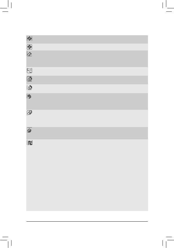
1-3-1 Installing the CPU
A. Locate the alignment keys on the motherboard CPU socket and the notches on the CPU.
LGA1150 CPU Socket
Alignment Key |
Alignment Key |
Pin One Corner of the CPU Socket
LGA1150 CPU
Notch |
Notch |
Triangle Pin One Marking on the CPU
Hardware Installation |
- 14 - |
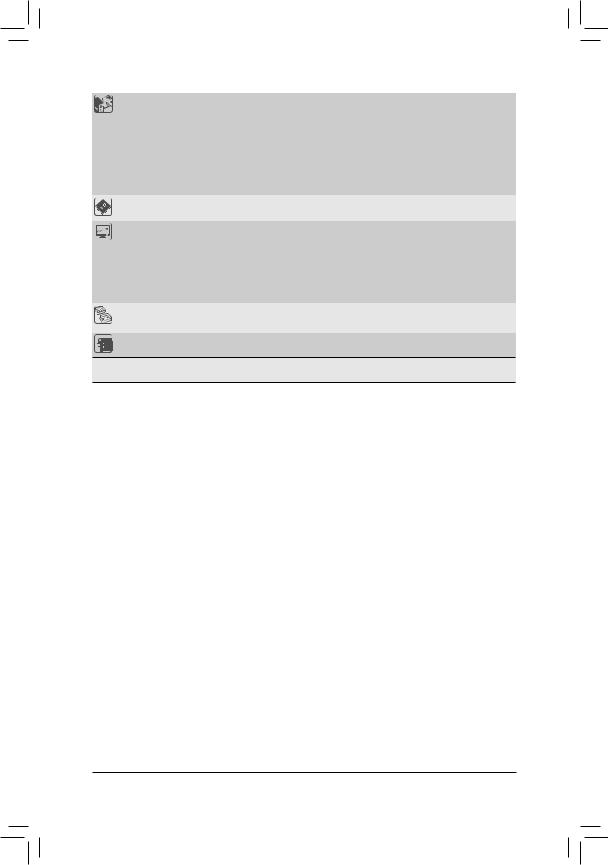
B. Follow the steps below to correctly install the CPU into the motherboard CPU socket.
Before installing the CPU, make sure to turn off the computer and unplug the power cord from the power outlet power plug to prevent any damage to prevent damage to the CPU.
Step 1:
Gently press the CPU socket lever handle down and away from the socket with your finger. Then completely lift the CPU socket lever and the metal load plate will be lifted as well.
Step 3:
Hold the CPU with your thumb and index fingers.
Align the CPU pin one marking (triangle) with the pin one corner of the CPU socket (or you may align the CPU notches with the socket alignment keys) and gently insert the CPU into position.
Step 5:
Push the CPU socket lever back into its locked position.
Step 2:
Remove the CPU socket cover as shown. Hold your index finger down on the rear grip of the socket cover and use your thumb to lift up the front edge (next to the "REMOVE" mark) and then remove the cover. (DO NOT touch socket contacts. To protect the CPU socket, always replace the protective socket cover when the CPU is not installed.)
Step 4:
Once the CPU is properly inserted, use one hand to hold the socket lever and use the other to lightly replace the load plate. When replacing the load plate, make sure the front end of the load plate is under the shoulder screw.
NOTE:
Hold the CPU socket lever by the handle, not the lever base portion.
- 15 - |
Hardware Installation |
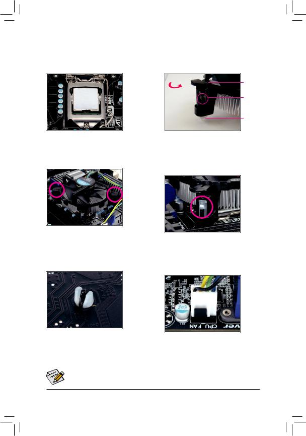
1-3-2 Installing the CPU Cooler
Follow the steps below to correctly install the CPU cooler on the motherboard. (The following procedure uses
Intel® boxed cooler as the example cooler.)
Direction of the Arrow Sign on the Male Push Pin
Male Push
Pin
The Top
of Female
Push Pin
Female
Push Pin
Step 1:
Apply an even and thin layer of thermal paste on the surface of the installed CPU.
Step 3:
Place the cooler atop the CPU, aligning the four push pins through the pin holes on the motherboard. Push down on the push pins diagonally.
Step 5:
After the installation, check the back of the motherboard. If the push pin is inserted as the picture above shows, the installation is complete.
Step 2:
Before installing the cooler, note the direction of the arrow sign on the male push pin. (Turning the push pin along the direction of the arrow is for removing the cooler, and the opposite direction is for installing it..)
Step 4:
You should hear a "click" when pushing down each push pin. Check that the Male and Female push pins are joined closely. (Refer to your CPU cooler installation manual for instructions on installing the cooler.)
Step 6:
Finally, attach the power connector of the CPU cooler to the CPU fan header (CPU_FAN) on the motherboard.
Use extreme care when removing the CPU cooler because the thermal grease/tape between the CPU cooler and CPU may adhere to the CPU. Inadequately removing the CPU cooler may damage
the CPU. |
|
Hardware Installation |
- 16 - |
1-4 Installing the Memory
Read the following guidelines before you begin to install the memory:
•Make sure that the motherboard supports the memory. It is recommended that memory of the same capacity, brand, speed, and chips be used.
•Always turn off the computer and unplug the power cord from the power outlet before installing the memory to prevent hardware damage.
•Memory modules have a foolproof design. A memory module can be installed in only one direction. If you are unable to insert the memory, switch the direction.
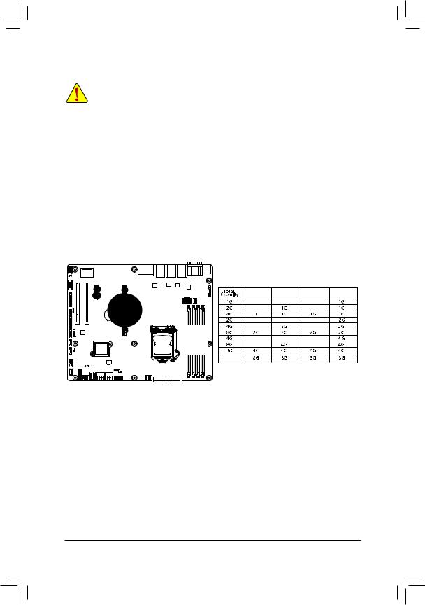
1-4-1 Dual Channel Memory Configuration
This motherboard provides four DDR3 memory sockets and supports Dual Channel Technology. When the memory is installed, the BIOS will automatically detect the specifications and capacity of the memory. Enabling Dual Channel memory mode will double the original memory bandwidth.
The four DDR3 memory sockets are divided into two channels and each channel has two memory sockets as following:
Channel 1: DDR3_P0_A0, DDR3_P0_A1
Channel 2: DDR3_P0, B0, DDR3_P0_B1
DDR3_P0_B1
DDR3_P0_B0
DDR3_P0_A1
DDR3_P0_A0
DDR3_P0_A0 DDR3_P0_A1 DDR3_P0_B0 DDR3_P0_B1
32
Due to CPU limitations, read the following guidelines before installing the memory in Dual Channel mode.
1.Dual Channel mode cannot be enabled if only one DDR3 memory module is installed.
2.When enabling Dual Channel mode with two or four memory modules, it is recommended that memory of the same capacity, brand, speed, and chips be used for optimum performance.
- 17 - |
Hardware Installation |
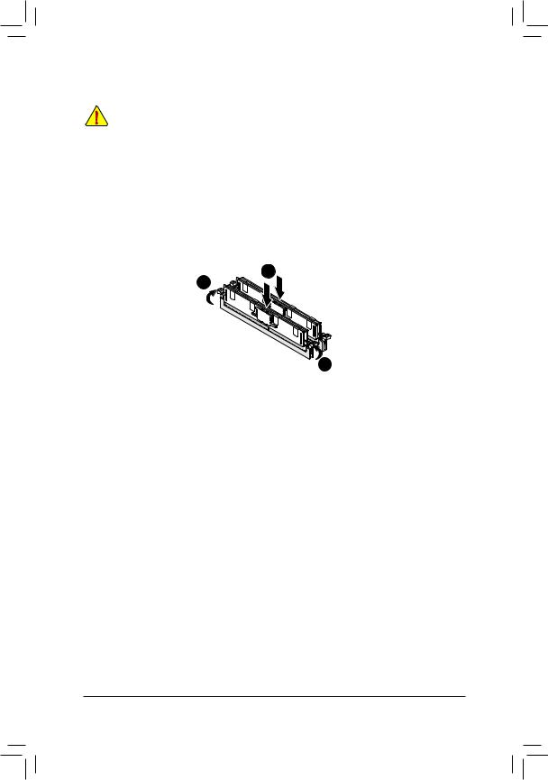
1-4-2 Installing a Memory
Before installing a memory module, make sure to turn off the computer and unplug the power cord from the power outlet to prevent damage to the memory module.
Be sure to install DDR3 DIMMs on this motherboard.
Installation Step:
Step 1. Insert the DIMM memory module vertically into the DIMM slot, and push it down. Step 2. Close the plastic clip at both edges of the DIMM slots to lock the DIMM module. NOTE! DIMM must be populated in order starting from DDR3_P0_A0 socket.
For dual-channel operation, DIMMs must be installed in matched pairs.
Step 3. Reverse the installation steps when you wish to remove the DIMM module.
1
2
2
Hardware Installation |
- 18 - |
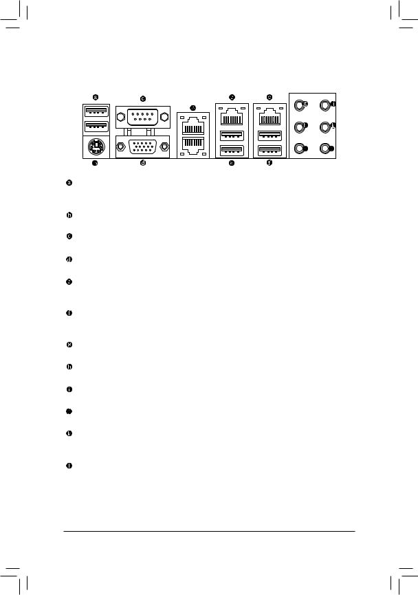
1-5 Back Panel Connectors
USB 2.0 Port
The USB port supports the USB 2.0 specification. Use this port for USB devices such as a USB keyboard/mouse, USB printer, USB flash drive and etc.
PS/2 Keyboard/Mouse Port
Coonnect a PS/2 keyboard or mouse to this port.
Serial Port
Connects to serial-based mouse or data processing devices.
VGA Port
The video in port allows connect to video in, which can also apply to video loop thru function.
RJ-45 LAN Port
The Gigabit Ethernet LAN port provides Internet connection at up to 1 Gbps data rate. The following describes the states of the LAN port LEDs.
USB 3.0 Port
The USB port supports the USB 3.0 specification. Use this port for USB devices such as a USB keyboard/mouse, USB printer, USB flash drive and etc.
Center/Subwoofer Speaker Out Jack (Orange)
Use this audio jack to connect center/subwoofer speakers in a 5.1/7.1-channel audio configuration.
Rear Speaker Out Jack (Black)
Use this audio jack to connect rear speakers in a 7.1-channel audio configuration.
Side Speaker Out Jack (Gray)
Use this audio jack to connect side speakers in a 4/5.1/7.1-channel audio configuration.
Line In Jack (Blue)
The default line in jack. Use this audio jack for line in devices such as an optical drive, walkman, etc.
Line Out Jack (Green)
The default line out jack. Use this audio jack for a headphone or 2-channel speaker. This jack can be used to connect front speakers in a 4/5.1/7.1-channel audio configuration.
Mic In Jack (Pink)
The default Mic in jack. Microphones must be connected to this jack.
- 19 - |
Hardware Installation |

|
|
|
|
|
|
|
|
|
|
|
|
|
I210/RTL8111F Speed LED: |
|
Link/Activity LED: |
||
|
|
|
|
|
|
|
|
|
|
|
|
|
|
|
|
|
|
|
|
|
|
|
|
|
|
|
Link |
State |
Description |
|
State |
Description |
|||
Speed LED |
|
|
|
|
|
Yellow On |
1 Gbps data rate |
|
On |
Link between system and network or no |
|||||||
|
|
|
|
|
Activity LED |
|
|||||||||||
|
|
|
|
|
Yellow Blink |
Identify 1 Gbps data |
|
|
access |
||||||||
|
|
|
|
|
|
|
|
|
|
|
|
|
|
|
|||
|
|
|
|
|
|
|
|
|
|
|
|
|
|
rate |
|
Blinking |
Data transmission or receiving is occurring |
|
|
|
|
|
|
|
|
|
|
|
|
|
Green On |
100 Mbps data rate |
|
Off |
No data transmission or receiving is occurring |
|
|
|
|
|
|
|
|
|
|
|
|
|
|||||
|
|
|
|
|
|
|
|
|
|
|
|
|
Green Blink |
Identify 100 Mbps data |
|
|
|
|
|
|
|
|
|
|
|
|
|
|
|
|
|
|
|
||
10/100/1000 LAN Port |
|
rate |
|
|
|
||||||||||||
|
|
|
|
|
|
|
|
|
|
|
|
|
Off |
10 Mbps data rate |
|
|
|
•When removing the cable connected to a back panel connector, first remove the cable from your device and then remove it from the motherboard.
•When removing the cable, pull it straight out from the connector. Do not rock it side to side to prevent an electrical short inside the cable connector.
Hardware Installation |
- 20 - |
1-6 Internal Connectors
22 |
|
23 |
|
24 |
|
19 |
8 |
15 |
2 |
3 |
|
26 |
|
21 25 |
27 |
16 |
|
14
13 |
|
|
|
|
|
28 |
|
|
|
|
|
|
31 |
|
18 |
34 |
35 |
32 |
30 |
|
33 |
29 |
||
|
17 |
5 9 |
11 |
12 |
20 |
6 |
7 |
1 |
|
4 |
10 |
|
|
|
|
|
|
1) |
ATX1 |
|
|
|
|
19) |
COM1 |
|
2) |
P12V_AUX1 |
|
|
|
|
20) |
TPM |
|
3) |
CPU0_FAN (CPU Fan) |
|
|
21) |
SATA_SGP1 |
|||
4) |
SYS_FAN1 (System Fan) |
|
22) |
F_AUDIO |
||||
5) |
SYS_FAN2 (System Fan) |
|
23) |
SPDIF_IN1 |
||||
6) |
SYS_FAN3 (System Fan) |
|
24) |
SPDIF_OUT1 |
||||
7) |
SYS_FAN4 (System Fan) |
|
25) |
LAN3_ACT |
||||
8) |
PMBUS |
|
|
|
|
26) |
LAN4_ACT |
|
9) |
SATA0 |
|
|
|
|
27) |
BAT |
|
10) |
SATA1 |
|
|
|
|
28) |
ME_UPDATE |
|
11) |
SATA_2_3 |
|
|
|
|
29) |
CASE_OPEN |
|
12) |
SATA_4_5 |
|
|
|
|
30) |
BIOS_RCVR |
|
13) |
SATA6/7 |
|
|
|
|
31) |
CLR_CMOS |
|
14) |
SATA8/9 |
|
|
|
|
32) |
PCH_ME |
|
15) |
FP_1 |
|
|
|
|
33) |
BIOS_PWD |
|
16) |
BP_1 |
|
|
|
|
34) |
SATA_DOM0 |
|
17) |
F_USB3 |
|
|
|
|
35) |
SATA_DOM1 |
|
18) |
F_USB2 |
|
|
|
|
|
|
|
- 21 - |
Hardware Installation |

Read the following guidelines before connecting external devices:
•First make sure your devices are compliant with the connectors you wish to connect.
•Before installing the devices, be sure to turn off the devices and your computer. Unplug the power cord from the power outlet to prevent damage to the devices.
•After installing the device and before turning on the computer, make sure the device cable has been securely attached to the connector on the motherboard.
- 22 - |
Hardware Installation |
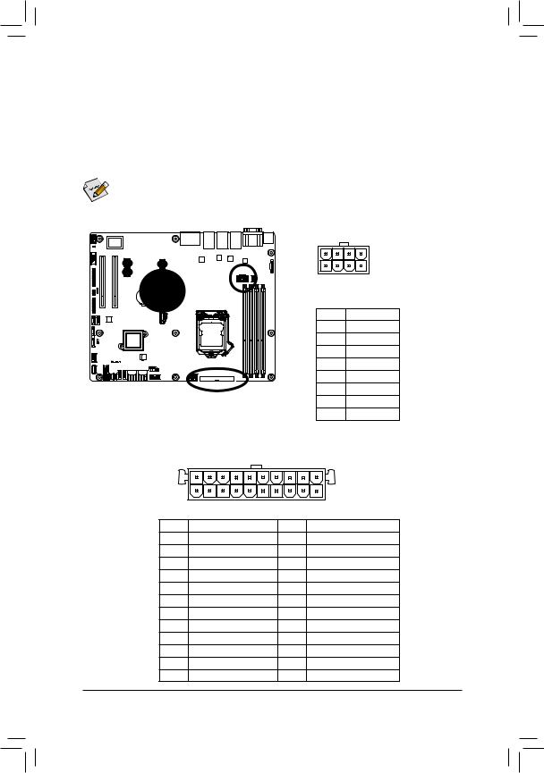
1/2) ATX1/P12V_AUX1 (2x12 Main Power Connector and 2x4 12V Power Connector)
With the use of the power connector, the power supply can supply enough stable power to all the components on the motherboard. Before connecting the power connector, first make sure the power supply is turned off and all devices are properly installed. The power connector possesses a foolproof design. Connect the power supply cable to the power connector in the correct orientation. The 12V power connector mainly supplies power to the CPU. If the 12V power connector is not connected, the computer will not start.

 To meet expansion requirements, it is recommended that a power supply that can withstand high
  power consumption be used (500W or greater). If a power supply is used that does not provide the required power, the result can lead to an unstable or unbootable system.
P12V_AUX1
8 |
5 |
4 |
1 |
|
|
|
Pin No. |
Definition |
|
|
|
1 |
GND |
|
|
|
2 |
GND |
|
|
|
3 |
GND |
|
|
|
4 |
GND |
|
|
|
5 |
+12V |
|
|
|
6 |
+12V |
|
|
|
7 |
+12V |
|
|
|
8 |
+12V |
24 |
|
|
13 |
|
ATX1 |
|
|
1 |
|
12 |
|
|
|
|
Pin No. |
Definition |
Pin No. |
Definition |
|
1 |
3.3V |
13 |
3.3V |
|
2 |
3.3V |
14 |
-12V |
|
3 |
GND |
15 |
GND |
|
4 |
+5V |
16 |
PS_ON |
|
5 |
GND |
17 |
GND |
|
6 |
+5V |
18 |
GND |
|
7 |
GND |
19 |
GND |
|
8 |
Power Good |
20 |
-5V |
|
9 |
5VSB (stand by +5V) |
21 |
+5V |
|
10 |
+12V |
22 |
+5V |
|
11 |
+12V |
23 |
+5V |
|
12 |
3.3V |
24 |
GND |
|
Hardware Installation |
- 23 - |
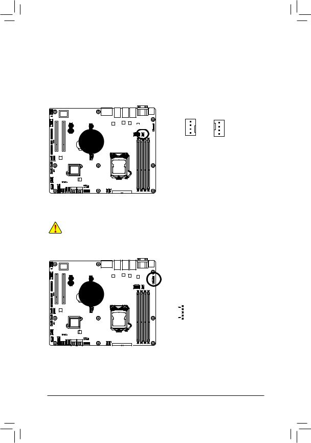
3/4/5/6/7) CPU0_FAN/SYS_FAN1/SYS_FAN2/SYS_FAN3/SYS_FAN4 (CPU Fan/System Fan Headers)
The motherboard has a 4-pin CPU fan header (CPU0_FAN), and four 4-pin (SYS_FAN1/SYS_FAN2/
SYS_FAN3/SYS_FAN4) system fan headers. Most fan headers possess a foolproof insertion design. When connecting a fan cable, be sure to connect it in the correct orientation (the black connector wire is the ground wire). The motherboard supports CPU fan speed control, which requires the use of a CPU fan with fan speed control design. For optimum heat dissipation, it is recommended that a system fan be installed inside the chassis.
CPU0_FAN 1
CPU0_FAN
1 SYS_FAN1/2/3/4
CPU0_FAN/SYS_FAN1/2/3/4:
Pin No. |
Definition |
1 |
GND |
2 |
+12V |
3 |
Sense |
4 |
Speed Control |
|
|
|
|
|
|
|
|
SYS_FAN2 |
SYS_FAN3 |
|
SYS_FAN4 |
|
|
|
|||
|
SYS_FAN1 |
|
|
|
|
•Be sure to connect fan cables to the fan headers to prevent your CPU and system from overheating. Overheating may result in damage to the CPU or the system may hang.
•These fan headers are not configuration jumper blocks. Do not place a jumper cap on the headers.
8)PMBUS (PMBus connector)
|
|
|
Pin No. |
Definition |
|
1 |
|
1 |
SMB CLK |
|
|
2 |
SMB DATA |
|
|
|
|
||
|
|
|
3 |
SMB Alert |
|
|
|
4 |
GND |
|
|
|
5 |
3.3V Sense |
|
|
|||
|
5 |
|||
|
|
|
|
|
|
|
|
|
- 24 - |
Hardware Installation |
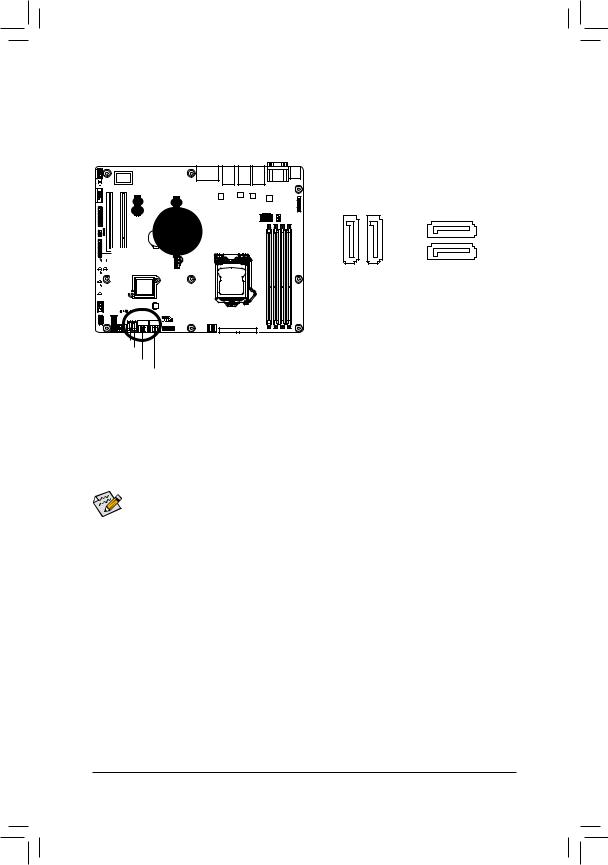
9/10/11/12/13/14) SATA0/SATA1/SATA_2_3/SATA_4_5/SATA6/SATA7/SATA8/SATA9 (SATA 6Gb/s Connectors)
The SATA connectors conform to SATA 6Gb/s standard and are compatible with SATA 3Gb/s and 1.5Gb/s standard. Each SATA connector supports a single SATA device.
SATA9


 SATA8
SATA8

 SATA7
SATA7


 SATA6
SATA6
SATA0
SATA1
SATA_2_3
SATA_4_5
7 |
7 |
|
|
7 |
1 |
|
7 |
1 |
1 |
1 |
|
When SATA_DOM0/1 jumper When SATA_DOM0/1 jumper are set to 1-2 pin: are set to 2-3 pin:
Pin No. |
Definition |
1 |
GND |
2 |
TXP |
3 |
TXN |
4 |
GND |
5 |
RXN |
6 |
RXP |
7 |
P5V |
Pin No. |
Definition |
1 |
GND |
2 |
TXP |
3 |
TXN |
4 |
GND |
5 |
RXN |
6 |
RXP |
7 |
GND |
• A RAID 0 or RAID 1 configuration requires at least two hard drives. If more than two hard drives are configured, the total number of hard drives must be an even number.
• A RAID 10 configuration requires four hard drives.
(Note) When a RAID configuration is built across the SATA 6Gb/s channels, the system performance of the RAID configuration may vary depends on the devices are connected.
- 25 - |
Hardware Installation |
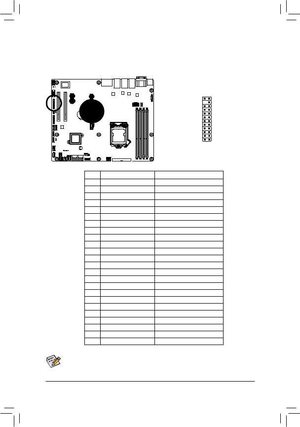
15)FP_1 (Front Panel Header)
Connect the power switch, reset switch, chassis intrusion switch/sensor and system status indicator on the chassis to this header according to the pin assignments below. Note the positive and negative pins before connecting the cables.
1 2
|
|
23 24 |
Pin No. |
Signal Name |
Definition |
1 |
PWLED+ |
Power LED Signal anode (+) |
2 |
5VSB |
5V Stanndby Power |
3 |
NC |
No Pin |
4 |
NC |
No Connect |
5 |
PWLED- |
Power LED Signal cathode(-) |
6 |
NC |
No Connect |
7 |
HD+ |
Hard Disk LED Signal anode (+) |
8 |
NC |
No Connect |
9 |
HD- (GND) |
Hard Disk LED Signal cathode(-) |
10 |
NC |
No Connectthode(-) |
11 |
PWB+ |
Power Button Signal anode (+) |
12 |
L1_LINK |
LAN1link LED Signal |
13 |
PWB+_GND |
Power Button Signal cathode(-) |
14 |
L1_ACT |
LAN1 active LED Signal cathode(-) |
15 |
RST_BTN+ |
Reset button Signal anode (+) |
16 |
SENSOR_SDA |
SMBus Data Signal |
17 |
RST_BTN_GND |
Reset button Signal cathode(-) |
18 |
SENSOR_SCL |
SMBus Clock Signal |
19 |
NC |
No Connect |
20 |
CASE_OPEN- |
Chassis intrusion Signal cathode(-) |
21 |
NC |
No Connect |
22 |
L2_LINK |
LAN2 Link LED Signal cathode(-) |
23 |
NMI_SW- |
NMI switch Signal cathode(-) |
24 |
L2_ACT |
LAN2 active LED Signal cathode(-) |
The front panel design may differ by chassis. A front panel module mainly consists of power switch, reset switch, power LED, hard drive activity LED, speaker and etc. When connecting your chassis front panel module to this header, make sure the wire assignments and the pin assignments are matched correctly.
- 26 - |
Hardware Installation |
16) BP_1 (HDD Back Plane Board Hearders)
|
|
|
|
Pin No. |
Definition |
|
1 |
NC |
1 2 |
2 |
PCH_THROTTLE_N |
3 |
NC |
|
|
4 |
NC |
|
5 |
NC |
|
6 |
GND |
|
7 |
KEY |
|
8 |
RresetL_BRB |
|
9 |
GND |
|
10 |
BP_ALED_N |
25 26 |
11 |
BP_LED_G_N |
|
12 |
GND |
|
13 |
NC |
|
14 |
GND |
|
15 |
GND |
|
16 |
SMB_BPB1_DATA |
|
17 |
GND |
|
18 |
SMB_BPB1_CLK |
|
19 |
P_3V3_AUX |
|
20 |
BP_HDD_TYPE |
|
21 |
P_3V3_AUX |
|
22 |
NC |
|
23 |
GND |
|
24 |
KEY |
|
25 |
BP_PRESENSE |
|
26 |
GND |
|
|
|
- 27 - |
Hardware Installation |
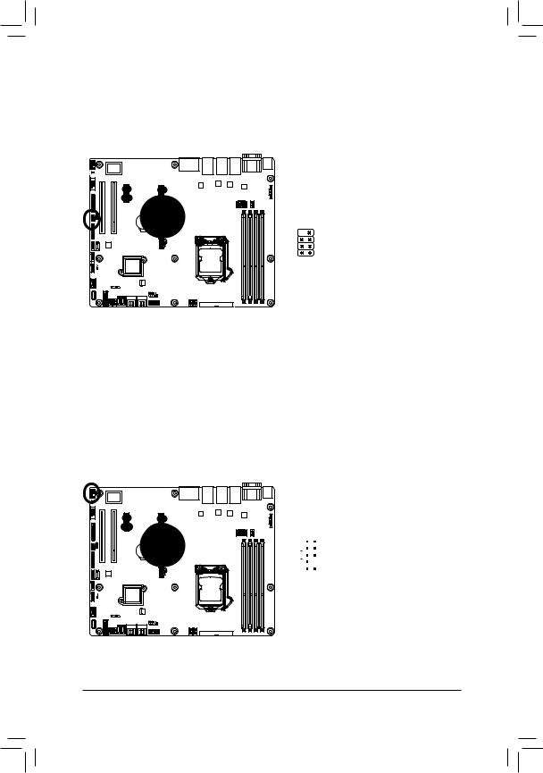
17)F_USB3 (USB 3.0 Header)
The headers conform to USB 3.0 specification. Each USB header can provide two USB ports via an optional USB bracket. For purchasing the optional USB bracket, please contact the local dealer.
|
|
Pin No. |
Definition |
|
|
1 |
Power |
20 1 |
|
2 |
IntA_P1_SSRX- |
|
3 |
IntA_P1_SSRX+ |
|
|
|
||
|
|
4 |
GND |
|
|
5 |
IntA_P1_SSTX- |
|
|||
|
|||
|
|
6 |
IntA_P1_SSTX+ |
|
|
7 |
GND |
11 10 |
|||
|
|
8 |
IntA_P1_D- |
|
|
9 |
IntA_P1_D+ |
|
|
10 |
NC |
|
|
11 |
IntA_P2_D+ |
|
|
12 |
IntA_P2_D- |
|
|
13 |
GND |
|
|
14 |
IntA_P2_SSTX+ |
|
|
15 |
IntA_P2_SSTX- |
|
|
16 |
GND |
|
|
17 |
IntA_P2_SSRX+ |
|
|
18 |
IntA_P2_SSRX- |
|
|
19 |
Power |
|
|
20 |
No Pin |
|
|
|
|
18)F_USB2 (USB 2.0 Header)
The headers conform to USB 2.0/1.1 specification. Each USB header can provide two USB ports via an optional USB bracket. For purchasing the optional USB bracket, please contact the local dealer.
|
|
|
Pin No. |
Definition |
|
|
|
1 |
Power (5V) |
1 |
2 |
|
2 |
Power (5V) |
|
3 |
USB DX- |
||
|
|
|
||
|
|
|
4 |
USB DY- |
|
|
|||
|
|
|
5 |
USB DX+ |
|
|
|||
|
|
|
6 |
USB DY+ |
|
|
|
7 |
GND |
9 |
10 |
|||
|
|
|
8 |
GND |
|
|
|
9 |
No Pin |
|
|
|
10 |
NC |
Hardware Installation |
- 28 - |
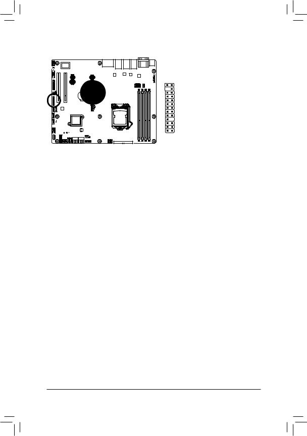
19) COM1 (Serial Port Header)
The COM header can provide one serial port via an optional COM port cable. For purchasing the optional COM port cable, please contact the local dealer.
|
|
|
Pin No. |
Definition |
1 |
2 |
|
1 |
NDCD- |
|
|
|
2 |
NSIN |
|
|
|||
|
|
|
3 |
NSOUT |
|
|
|
4 |
NDTR- |
|
|
|||
|
|
|
5 |
GND |
|
|
|
6 |
NDSR- |
9 |
10 |
|
7 |
NRTS- |
|
|
|
8 |
NCTS- |
|
|
|
9 |
NRI- |
|
|
|
10 |
No Pin |
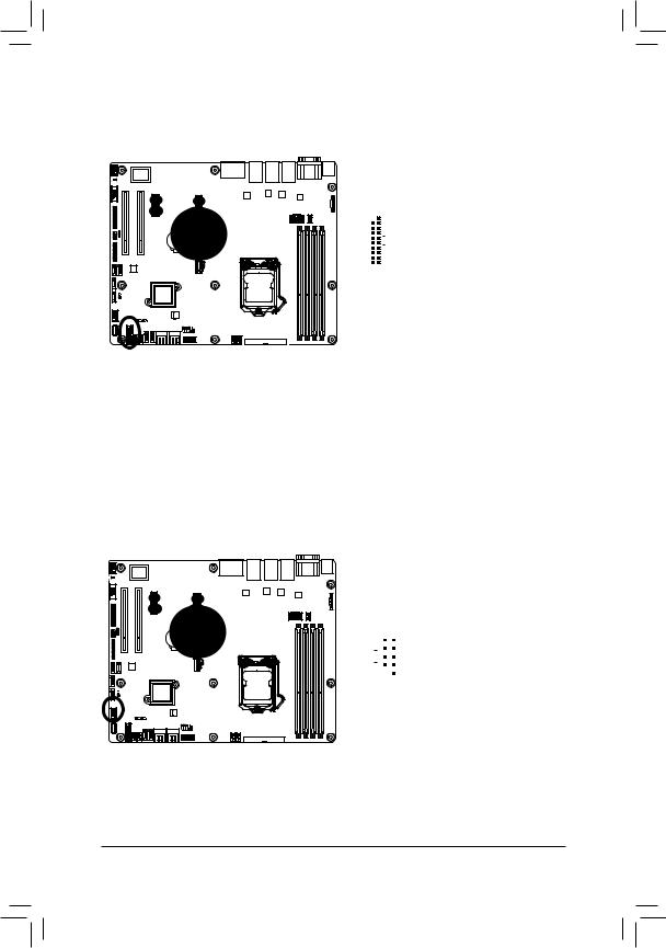
20) TPM (TPM Module connector)
13 |
1 |
14 |
2 |
|
|
Pin No. |
Definition |
1 |
CLK_33M_TPM |
2 |
P_3V3_AUX |
3 |
LPC_RST_DEBUG |
4 |
P3V3 |
5 |
LPC_LAD0 |
6 |
IRQ_SERIAL |
7 |
LPC_LAD1 |
8 |
TPM_DET_N |
9 |
LPC_LAD2 |
10 |
NC |
11 |
LPC_LAD3 |
12 |
GND |
13 |
LPC_FRAME_N |
14 |
GND |
- 29 - |
Hardware Installation |
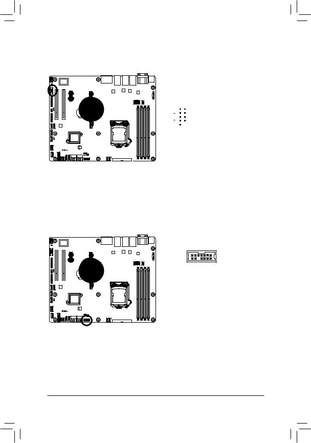
21)SATA_SGP1 (SATA SGPIO Header)
SGPIO is stands for Serial General Purpose Input/Output which is a 4-signal (or 4-wire) bus used between a Host Bus Adapter (HBA) and a backplane. Out of the 4 signals, 3 are driven by the HBA and 1 is driven by the backplane. Typically, the HBA is a storage controller located inside a server, desktop, rack or workstation computer that interfaces with Hard disk drives (HDDs) to store and retrieve data.
2 |
1 |
Pin No. |
Definition |
|
1 |
SGPIO_SATA_DATAIN |
|||
|
|
2 |
No Pin |
|
|
|
3 |
SGPIO_SATA_DATAOUT |
|
8 |
7 |
4 |
GND |
|
5 |
GND |
|||
|
|
|||
|
|
6 |
SGPIO_SATA_LOAD |
|
|
|
7 |
NC |
|
|
|
8 |
SGPIO_SATA_CLOCK |
|
|
|
|
|
22)F_AUDIO (Front Panel Audio Header)
The front panel audio header supports Intel High Definition audio (HD). You may connect your chassis front panel audio module to this header. Make sure the wire assignments of the module connector match the pin assignments of the motherboard header. Incorrect connection between the module connector and the motherboard header will make the device unable to work or even damage it.
|
|
|
Pin No. |
Definition |
|
|
|
1 |
MIC2_L |
1 |
2 |
|
2 |
GND |
|
3 |
MIC2_R |
||
|
|
|
||
|
|
|
||
|
|
|
4 |
FP_AUD_DET |
|
|
|
5 |
LINE2_R |
|
|
|
||
|
|
|
6 |
MIC2_JD |
9 |
10 |
|
7 |
GND |
|
|
|
||
|
|
|
8 |
No Pin |
|
|
|
9 |
LINE2_L |
|
|
|
10 |
LINE2_JD |
Hardware Installation |
- 30 - |
Loading...