

Page 1
INSTALLATION
INSTR UCTIONS
Wash
disinfector
S-606
Serial no. 970001-
5000375-00
0301
Produced: 1999
Page 2

Installation
Foreword
These Operating Instructions are standard for all models referred to below:
W all-mounted
Free-standing with tipping protection
The models are supplied with different levels of equipment:
Rotator
Process or spray dispensing
De-scaler dispensing
Rinse-aid dispensing
Inserts
Central steam supply
Models are also available for different voltages.
2 Edition 990426 5000375-00
Page 3

Installation
Contents
Foreword _______________________________________________ 2
Safety regulations ________________________________________ 4
General safety rules ______________________________________ 4
Isolating device _________________________________________ 4
Description ____________________________________________ 4
W arning symbols ________________________________________ 4
Unpacking ______________________________________________ 5
Installing the wash disinfector_______________________________ 6
Free-standing___________________________________________ 6
W all-mounted __________________________________________ 7
Connection of water ___________________________________ 8
Connection to the drain _________________________________ 8
Electrical connection ___________________________________ 9
Functional check _________________________________________ 10
T echnical data ___________________________________________ 11
Component list ___________________________________________ 12
Electrical wiring diagram ___________________________________ 13
5000375-00 Edition 990426 3
Page 4
Safety regulations
The design of this machine incorporates a number of built-in safety
devices. To avoid personal injury, it is very important not to render these
safety devices ineffective by by-passing them.
General safety rules
• The machine shall be connected in accordance with the installation
instructions.
• The machine shall not be operated by minors.
• Installation and service operations shall be performed by personnel
with the appropriate training for this machine.
• The machine's lid lock shall not be by-passed under any circumstances.
• Leakage in the system, e.g. a worn lid seal, shall be repaired
immediately.
Installation
• Before performing any repair or service operations, the personnel
concerned shall study the relevant handbooks and service manuals.
• The machine must not be washed down with water.
• Care shall be taken when using corrosive detergents.
• Safety precautions in the presence of hot water and steam.
Isolating device
The machine shall always be provided with a separate isolating device in
the mains power supply mounted in a readily accessible position on a wall.
Description
The wash disinfector is intended for the cleaning and disinfection of reusable items such as basins, hand bowls and urinals. Disinfection in this
context means the destruction of all vegetative bacteria, fungal spores and
viruses, but not bacterial spores.
Warning symbols
This handbook contains various warnings, directions and advice of such
importance that we have decided to mark them specially. The following
layout and symbols are used:
This symbol marks a warning in the handbook text. Failure to heed this
warning can lead to more or less severe personal injury and, in some
cases, danger to life.
The symbol also marks warnings intended to prevent damage to the
appliance.
4 Edition 990426 5000375-00
Page 5
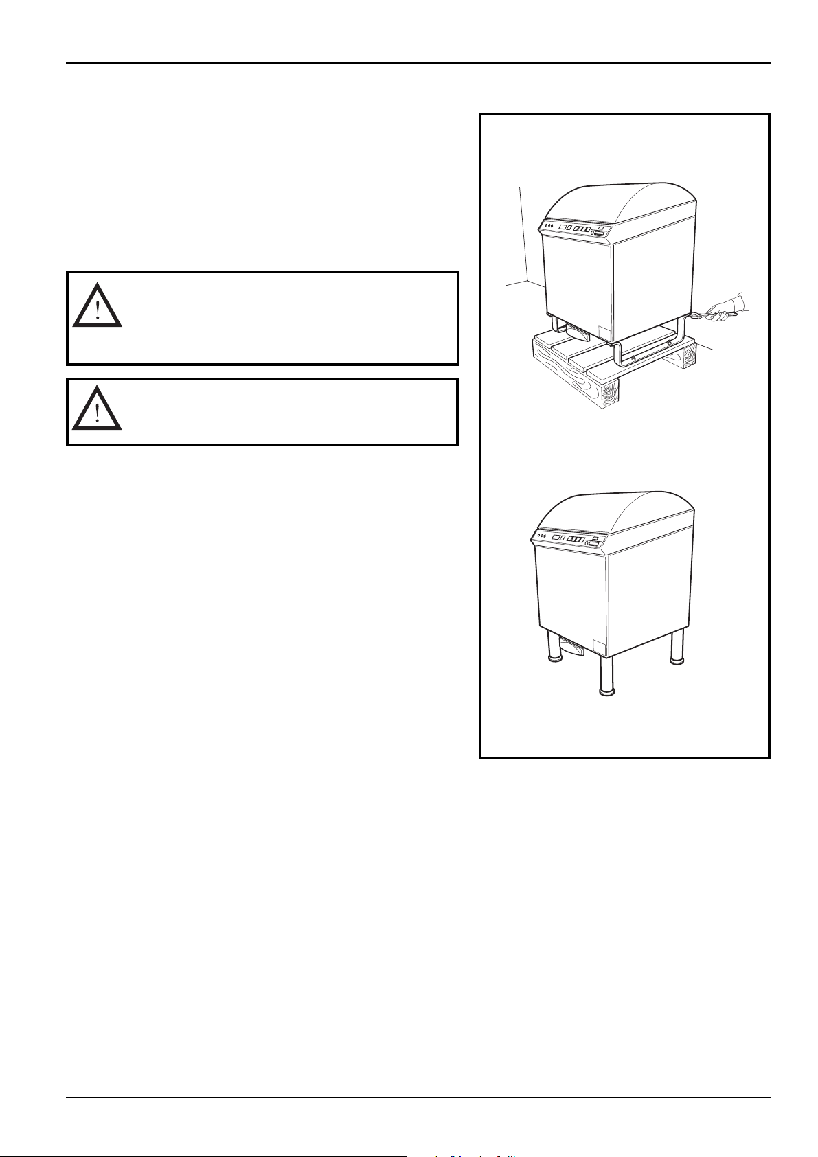
Unpacking
The wash disinfector is supplied bolted securely to a
freight pallet. Remove the packaging.
The following items shall accompany the delivery of the
wash disinfector:
1 wall bracket, plus 2 or 4 legs
1 folder containing documentation
N.B.
Before installation, check that the wash
disinfector has not suffered any transport
damage.
Care shall be taken when cutting the strap
over the lid. The lid opens of its own accord.
Installation
V670
V698
5000375-00 Edition 990426 5
Page 6
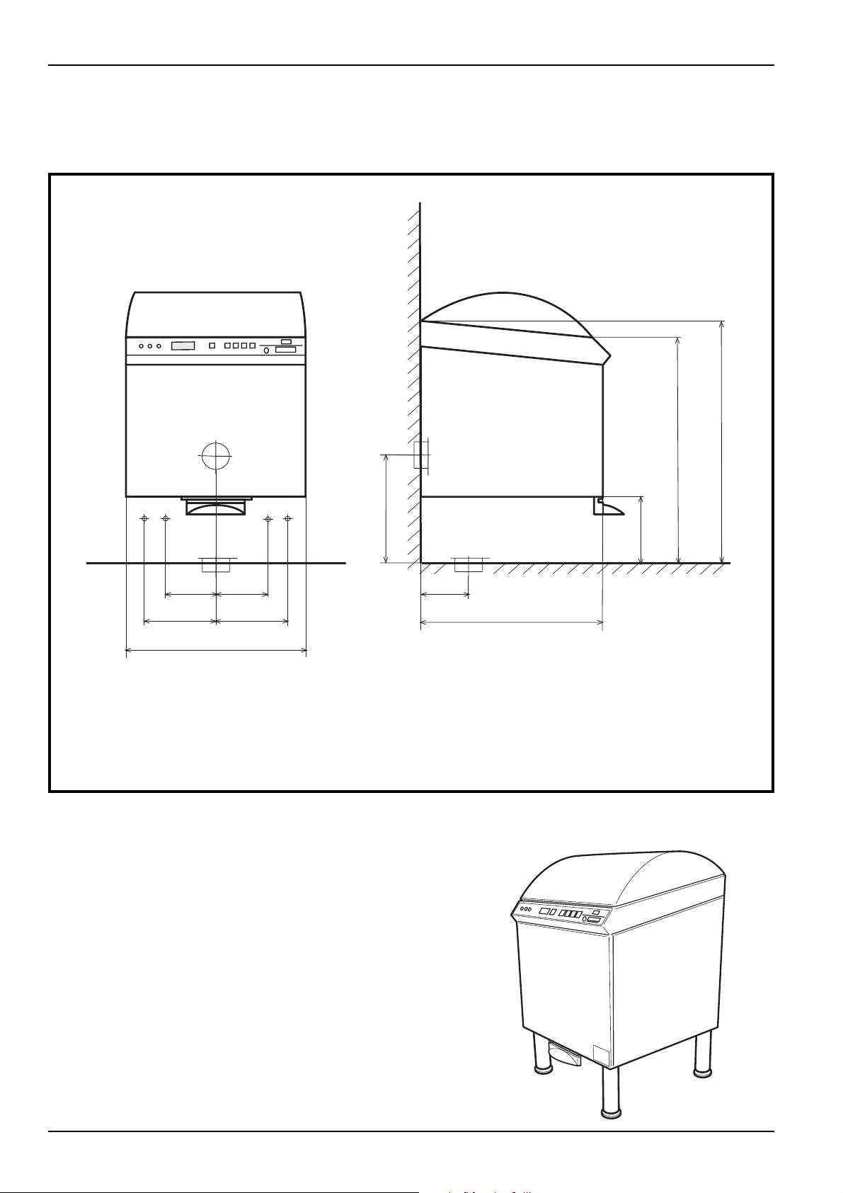
Installing the wash disinfector
3
Installation
900/930/960
800/830/860
1 2
180 180
255 255
V660
Free-standing
590
5
6
440/470/500
4
110
615
1. Hot water connection 1/2"
2. Cold water connection 1/2"
3. Drain connection, P, w all ø110 mm
4. Drain connection, S, floor ø110 mm
5. Electrical connection, cable 4 m
6. External steam supply 1/2"
250/280/310
Carry out the installation in the following sequence:
1 Remove the transport protection means used to anchor
the wash disinfector in the pallet. Fit the legs.
2. Connect the water connections.
3. Connect the drain connection.
4. Carry out the electrical installation.
5. Install the tipping protection.
V698
6 Edition 990426 5000375-00
Page 7
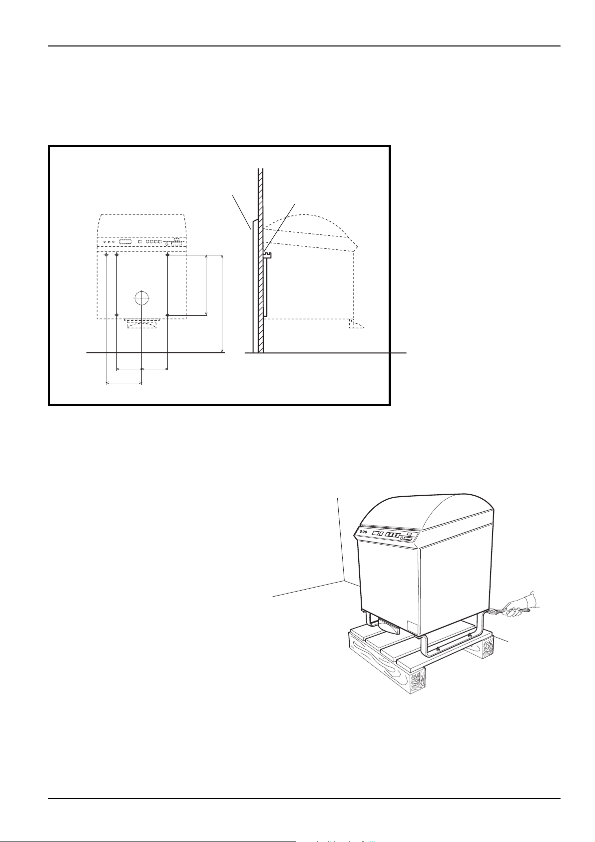
Wall-mounted
Carry out the installation in the following sequence:
1. Drill the hole pattern for the wall bracket, see the
Figure below:
Installation
Wall fixture
350
806
179,5
179,5
235,5
235,5
V669
2. Fit the wall bracket, using the wall fixture if the wall is
too weak.
Wall bracket
3. Remove the transport protection means, and hook the
machine on the wall bracket.
4. Connect the water connections.
5. Connect the drain connection.
6. Carry out the electrical installation.
V670
5000375-00 Edition 990426 7
Page 8
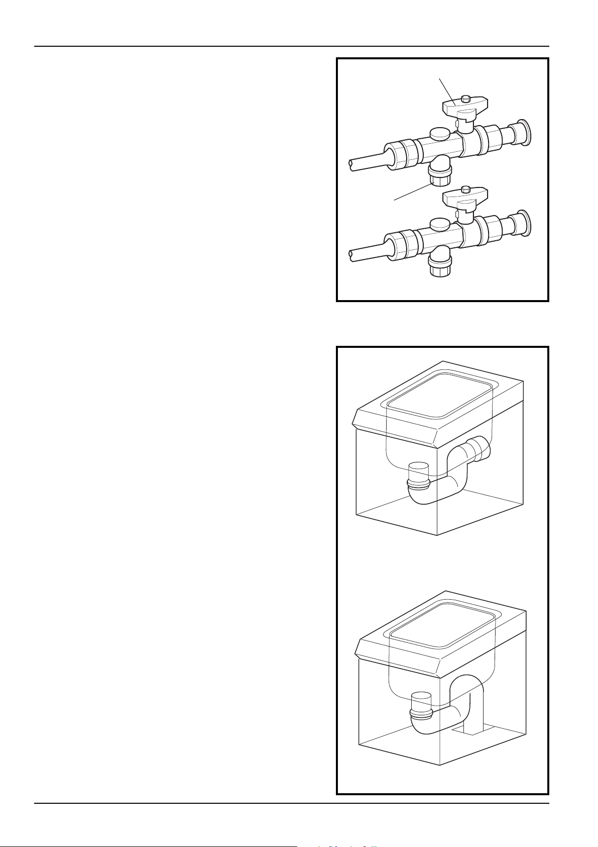
Connection of water
1. Flush through the water pipes that are to be
connected to the machine, to prevent blockage of the
filter and valves.
2. Connect the wash disinfector to the cold and hot
water .
The water connections must satisfy the following
requirements:
Installation
Shut-off valve
• The pipe dimensions shall permit a minimum water
flow of 20 l/min at 1 bar .
• The hot water temperature must be at least
+45°C.
3. Seal the connections with T eflon tape.
Connection to the drain
Connect the disinfector to the drain. The drain can be
connected either rearwards or downwards. The pipe
diameter is 110 mm.
Filter
V553
V661
V662
8 Edition 990426 5000375-00
Drain connection P in wall
Drain connection S in floor
Page 9

Installation
Electrical connection
1. Connect the cables to an isolating device, with a 3
mm breaking distance, positioned on the wall.
2. Connect to a protective earth and to the voltage
supply indicated on the rating plate. Check that the
connection is properly fused. The correct fuse value is
stated on the rating plate.
Isolating device
V659
5000375-00 Edition 990426 9
Page 10

Installation
Functional check
• Check that the wash disinfector is connected to the right voltage, as
indicated ion the rating plate.
• Open the water valves and switch on the operating switch. The message
”Ready for use. Select program” shall appear in the displa y window.
• If the machine is provided with metering of the cleaning agent: Presss
and check that the lamp in the button lights.
• Check that the incoming hot water is at the right temperature. The temperature shall be in the range 45 - 60°C.
• Start the Intensive program with the machine empty , and check that:
- the yellow lamp at L lights,
- the temperature increases continuously until the cooling phase starts,
- the pause for heating does not exceed ca. 10 minutes,
- the temperature reaches 90 °C,
- the green lamp at M lights, and the display window shows Program
ready .
Process running
S-606dekal
Process completed
&=q
• If the machine has a system for the cleaning agent and/or de-scaling agent:
Measure out the agent in a measuring glass. Ensure that the suction hose is
filled with the agent. Start a normal programme, and check that the
disinfector consumes the right quantity . For cleaning agent, the quantity/
programme is usually ca. 20 ml and for de-scaling agent is ca. 1.5 - 4.0 ml
(follow the supplier's recommendations).
• If the machine is equipped with a peripheral washing program:
Press button
running. N.B. Keep the button depressed during the entire process (ca. 10
seconds).
vv
v and check that the peripheral washing programme is
vv
• Check for the absence of water leaks. Tighten the connections and pipe
couplings, if necessary .
10 Edition 990426 5000375-00
Page 11

Installation
Technical data
Weight 90 - 105 kg
Width 590 mm
Depth 640 mm
Height 9 95 mm
Environmental requirements:
Maximum air humidity 80% at 31 °C
Room temperature 5-40 °C
Water consumption (without cooling*)
Economy programme 9 l/process
Normal programme 2 1 l/process
Intensive programme 2 4 l/process
* cooling ca 3 l.
Cold water
Connection 15 (1/2") m m
Pressure 70-800 kPa
Flow 20 l/min
Hot water
T emperature 45-60 °C
Connection 15 (1/2") m m
Pressure 70-800 kPa
Flow 20 l/min
Steam
connection 15 (1/2") mm
Pressure 30-300 kPa
consumption 0 , 3 kg/process
Drain ø 110 mm
Max. external temperature 4 0 °C
Noise level 60 dB(A)
Variant Electrical connection Fuse Po wer req.
L1 230 V, 1N+PE 50 Hz (TN) 1x20A 4.35 kW
L 2 230 V, 3+PE 50 Hz (TN) 3x16 A 5.36 kW
L 3 230/400 V, 3N+PE 50 Hz (TN) 3x10 A 5.36 kW
V 2 230 V, 1N+PE 50 Hz (TN) 1x10 A 1.01 kW
L 5 240 V, 2+PE 60 Hz (TN) 2x20 A 4.35 kW
V 3 240 V, 2+PE 60 Hz (TN) 2x10 A 1.36 kW
L 9 208 V, 2+PE 60 Hz (TN) 2x25 A 4.35 kW
V 4 208 V, 2+PE 60 Hz (TN) 2x10 A 1.36kW
L1 4 200 V, 2+PE 50 Hz (TN) 2x25 A 4.35 kW
V 5 200 V, 2+PE 50 Hz (TN) 2x10 A 1.01 kW
L1 8 200 V, 2+PE 60 Hz (TN) 2x25 A 4.35 kW
V 6 200 V, 2+PE 60 Hz (TN) 2x10 A 1.36 kW
L2 2 230V !N+PE 60 Hz (TN) 1x20A 4.35 kW
L2 4 230/400V3N+PE 60 Hz (TN) 3x10A 5.71 kW
V 7 230V 1N+PE 60 Hz (TN) 1x10A 1.36 kW
5000375-00 Edition 990426 11
Page 12

Installation
Component list
-S2
-S3
-S5
-S4
-A11
-M3
-TE1
-S7
-Y2
-Y5
-LS1
-LS2
-LS3
-LS4
-LS6
-S1
-M7
-T2
-M1
-LS5
V654
-A1 Control system, processor card
-A21 Control system, expansion card (option)
-A11 Control panel
-E1 Electric element in steam generator
-F1 Fuse for auxiliary transformer
-F2 24V fuse on processor card
-F3 Fuse for control voltage, phase 1
-F4 Fuse for control voltage, phase 2 (some connection
alternatives)
-F11 Overheating protection, steam generator
-K2 Contactor, element in steam generator
-LS1 Level sensor, tank
-LS2 Level sensor, de-scaling
-LS3 Level sensor, spray agent (option)
-LS4 level sensor, process (option)
-LS5 Leakage sensor
-LS6 Level sensor, rinse aid (option)
-M1 Motor, main pump
-M2 Motor pump, spray agent (option)
-M3 Motor pump, cleaning agent (option)
-M4 Motor pump, de-scaling
-Y1
-Y7
-S11
-M2
-E1
-Y6
-M6
-M9
-M4
-F11
-XPE
-S8
-K2
-A1
-F1, F2
-T1
-A21
-F3
-F4
-M6 Motor, door actuation/door lock
-M7 Motor pump, rinse-aid (option)
-M9 Motor, rotator (option)
-S1 Limit switch, disengages anti-trapping protection
-S2 Limit switch, anti-trapping protection
-S3 Limit switch, door closed
-S4 Limit switch, door open
-S5 Safety switch, door closed
-S7 Limit switch, rotator down (option)
-S8 Limit switch, rotator up (option)
-S11 Push-button for pedal
-T1 Control current transformer
-TE1 Temperature sensor PT 1000
-Y1 Solenoid valve, cold water (KV)
-Y2 Solenoid valve, hot water (VV)
-Y5 Solenoid valve, external cooling (option)
-Y6 Valve, external steam (option)
-Y7 Solenoid valve, condense cooling
-XPE Protective earthing rail
-T2 Transformer, 200-240/230V
N.B. Some components are extra equipment.
12 Edition 990426 5000375-00
Page 13

Installation
Electrical wiring diagram
5000375-00 Edition 990426 13
Page 14

Page 15

Page 16

Page 17

Page 18

Page 19

Page 20

Page 21

Page 22

Page 23

Page 24

Page 25

Page 26

Den här produkten är tillverkad av:
GETINGE DISINFECTION AB, Ljungadalsgatan 11, Box 1505, 351 15 Växjö, Sweden
 Loading...