

Page 1

EXIT MANUAL
The letters PACS stand for Programmable Autoclave Control System.
The object of the control system is to produce command s and transmit
these to the sterilizer components enabling for a number of sterilization
processes to be accomplished in accordance with a predicted pattern.
The command signals are generated by the control unit comput er program in combination with measurements of the process paramete r values. The latter consist mainly of times, temperatures and pressures.
Various equipment can be connected to the control unit for programming, monitoring and recording the sterilization processes.
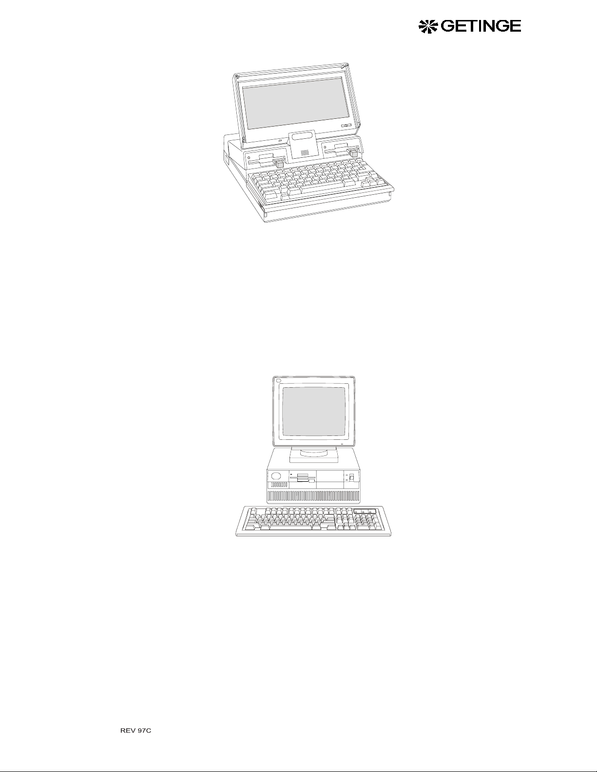
The operator communicates with the control unit via a control p anel or
a standard PC (OPC). The control panel is available in the versions OP1
and OP2, where OP1 is the smallest type and consists of two door operation keys and eight sig nal light diodes onl y.
The OP2 panel has a 102 x 25 mm LCD, six program selector keys, signal lights and up-dow n and right-left keys to display desir ed information in preprogramm ed windows. Programm ing can also be done by
means of the OP2, but this is limited to numeral values. The OP2 panel
is mainly designed for entering operator adjustable parameters.
There are connection ports in the PACS 2000 all owing a maximum of
two OP1s, two OP2s or one of each. Simultaneously with this combination, OPC can be connected , but only on e of all these can be the commanding unit at a time.
All operating panel s are made for monitoring the pro c esses by displaying any set parameter value as well as current values on request. All relevant data associated with a particular process such as batch No.,
operator No., date, etc., may be entered by the operator using OPC.
Documentation of programs, system definitions and process data can be
made by connecting a printer to OPC. A host computer can also be connected direct to the co ntrol unit CPU.
Where the demand requires a measuring an d monito ring system, co mpletely indepen de n t o f t h e control system, a PA CS SUPERVISOR system may be connected. This con tains a CPU, OP2 an d interfaces wi th
the CPU of the sterilizer control unit. The SUPERVISOR measurements are made by its own separate temperature and pressure sensors.
The computer contains a program for automatic calibration of temperature and pressure transducers. Alternatively correction constants, when
known, may be entered manually. Among PACS 2000 test fu nctions
there are facilities for activating analog and digital outputs and monitoring analog and digital inputs. With OPC or OPH, up to 16 service
alarms, flagged as display codes, can be programmed, based either upon
operation tim e in hours or number of ste rilizing c ycles. In bo th cases th e
maximum programmable d igits are 9999. Service a larms are displayed
also by OP2, but this panel will not allow for programming of these.
The hardware of the steri lizer control system contains the operating
panels easily locate in a suitable place. The CPU and po wer pack are
Click here to
Click here to
EXIT Manual
EXIT Manual
1
Page 2

placed in a separate electrical enclosure, connected to the operating panels.
Description of terms
STERILIZATION means the whole series of treatments to form a process in order to attain total killing of all viable organisms. This is in connection with autoclaves usually made up by air removal, heat treatment
and a drying phase.
STERILIZING means the actual killin g part, th e heat treatmen t, of the
total process.
Analogous to the two expressions above, STERILIZATION TIME
means the durability of the total process from the start until the goods
can be unloaded. PROCESS TIME is equal to sterilization time.
STERILIZING TIME represents that part of the process on ly during
which the programmed STERILIZING TEMPERATURE prevails in
the chamber.
EXIT MANUAL
PARAMETER in this context means the ELEMENTS WHICH
INFLUENCE the sterilization course. Examples of parameters in the
sterilization process are temperature, pressure, time, gas concentration,
etc. The PARAMETER VALUES may be fixed in the program or operator adjustable.
F
-VALUE is a time defined by the equ ation
0
t
T
k1–
t
()
------------------k
2
F
10
=
∫
0
0
×
dt
t = Time in minutes
T(t) =
k
= Constant within the range 0.0 - 150.0 oC. Usually 121.1 oC
1
= Constant withi n the range 0.0 - 99.9 oC. Usually 10.0 oC
k
2
The F
Load temperature at time t
. value is based upon the sterilizing time, required for the temper-
0
ature prevailing in each moment, being recalculated to the base temperature for steam sterilization, 121.1
o
C
The use of F
value is most common in the pharmaceutical field, where
0
often the time control of sterilization processes is based upon this value,
thereby utilizing t he heat appl ied du ring heat ing u p and cooli ng down .
By this method, heat sensitive products do not need to be exposed to
high temperatures for a longer period of time than required in obtaining
a sterile result.
2
Page 3
OP C
EXIT MANUAL
OP C is a standard IBM compatible PC with DOS and with backup utilities on hard disk and flop py. OP C is intend ed to be used for progra m
development. The menu tree includes menus for loading data on diskette or hard disk. OP C communicates with the PACS 2000 via a standard RS232 serial interface connected as COM1. COM2, if installed,
may be used for connecting a printer or a PROM programmer. In Local
mode it is possible to run the program without any PACS connected.
OP H
OP His identical to OP C with the extension that it can be connected to
a network includ ing more than one PAC S. OP H communicates wi th the
PACS 2000 via a standard RS485 serial interface. OP H is communicating with one PACS at a time.
3
Page 4

Screen lay-out
EXIT MANUAL
The screen is divided into six wind ows, each one displ aying differe nt
kind of information.
WINDOW 1
F1
PREV HELP
F2
F3
F4 F5 F6
WINDOW 2
WINDOW 4
WINDOW 5
WINDOW 6
F7
WINDOW 3
F8 F9
F10
Window 1 shows system date and time
shows connected sterilizer name and n umb er on
OP H
Window 2 shows sequence number and symbolic name for the
active PACS prog ra m in on -l i ne mo de a nd pr og ra m
version number in local mode
Window 3 shows symbolic name and sub-phase number for the
Window 4 shows all menu functions in the menu tree. Active
Window 5 describes the active function of the keys F1-F10
Window 6 shows menu handling messages for all menus except
Function keys F1-F10
The function of these keys are depending on the menu selected i n the
menu tree and will be shown in fully written out text in a window on the
display close to the appropriate key.
active PACS phase in on-line mode. Shows the text
”LOCAL MODE” when in that mode.
menu headline is displayed in the upper right corner
of the window.
process pictures.
In process pictures the left part of the window is used
for PACS error texts and the right part for PACS
information text s
4
Page 5

On line / Local mode
OP can operate in two modes, ONLINE mode and LOCAL mode. In
On-line mode the communicat ion link between OP and PACS is activated and the data base in the two units contain i dentical data . In local
mode OP works remote ly without any communi cation with PACS.
Local modes are available in version OPH and OPC.
The OPC / OPH menu tree
Below follows that part of the menu tree which is of use for the operator.
MODE MENU
MAIN MENU
Menu in frame is not available in Local Mode
START PROGRAM
ACTIVATE PROGRAM
EXIT MANUAL
PARAMETER INPUT
BATCH DEFINITION
SYSTEM MODE
Pass word level 1 required
NORMAL PROCESS PICTURE 1
NORMAL PROCESS PICTURE 2
ENLARGED PROCESS PICTURE
PLOT PROCESS PICTURE
Pass word level 2 required
5
Page 6

The OPC / OPH menu tree
Below follows that part of the menu tree which is of use for the service
man.
MODE MENU
MAIN MENU
EXIT MANUAL
START PROGRAM
ACTIVATE PROGRAM
PARAMETER INPUT
BATCH DEFINITION
SYSTEM MODE
SYSTEM PROGRAMMING
CALENDAR
CALIBRATION
ANALOG INPUT MANUAL CALIBRATION
ANALOG INPUT AUTOMATIC CALIBRATION
ANALOG OUTPUT MANUAL CALIBRATION
SERVICE
ERROR LOG
TEST FUNCTION
TEST ANALOG INPUT
TEST ANALOG OUTPUT
TEST DIGITAL INPUT
TEST DIGITAL OUTP UT
TEST USER FLAG
TEST SYSTEM FLAG
TEST PICTURE
TEST PRINTER
TEST LED
Menu in frame is not available in Local Mode
NORMAL PROCESS PICTURE 1
NORMAL PROCESS PICTURE 2
ENLARGED PROCESS PICTURE
PLOT PROCESS PICTURE
Pass word level 2 required
Pass word level 1 required
Pass word level 3 required
LOG-FILES
OP H only
6
Page 7

Passwords
EXIT MANUAL
Four passwor ds exists in the PACS 2000 and consists of four digits
0000-9999. The passwords are
operator password
•
needed to start restricted processes and to open doors after a process
failure
parameter password
•
needed to accept change of pr ogram parameters
service password
•
needed for entering maintenance menus
program password
•
needed for entering programming menus
The parameter password may, as an option, be exchanged to a pass key
connected to a dig ita l in put. The pass k ey overri des the para meter password.
Passwords at delivery:
The passwords set in the con trol system is revealed in a special docu ment delivered in a sealed envelope together with the sterilizer manuals.
Menu descriptions
Mode menu
This is the first menu shown after power-up. Here the operator can
choose which mode the OP should work in.
ON-LINE MODE for connection with PACS 2000 or
LOCAL MODE for stand alone op eration.
Alternative 3 in the menu ter m inates the program and returns to DOS.
Parameter code is required to use this alternative.
92/09/25 08:18:17
MODE MENU
1. ONLINE MODE
2. LOCAL MODE
3. EXIT
P 1 PROGRAM 1
STANDBY 01
F1 F2
PREV
F3
F4
F5 F6
F7
BAUDR
F8 F9
HELP
F10
MOM.EPS
7
Page 8

EXIT MANUAL
An alternative is highlighted with
alternative can also be highlighted by pressing the number of the desired
alternative.
Before ON-LINE MODE is activated PACS 2000 communication
baud rate can be altered. F7 sho ws a window were the operator can
choose betwee n the alterna tives 1200 , 2400, 4800 and 9600 vi a a choice
list. Default value is 9600 baud.
Valid only for OP H: If ON-LINE MODE is chosen a window i s
shown where the operator can specify which sterilizer he like to be connected to. Allowed values are: 1 - 99.
ON-LINE / LOCAL MODE
OP can operate in two modes, O N-LINE MO DE and LOCA L MOD E.
In ON-LINE MODE the communication link between OP and PACS
2000 is activated and the data bases in the two units contain s identical
data. In LOCAL MODE OP works without any communication to
PACS.
LOCAL MODE is avai lable on v ersion OP H and OP C while OP 3
always requires ON-LINE MODE.
Following menu functions are not available in LOCAL MODE:
ÏÐ
and selected with ENTER. A
•
START PROGRAM and all under lying menus.
•
CALIBRATION MENU and all underlying menus.
•
ERROR LOGG
•
TEST ANALOG INPUT
•
TEST ANALOG OUTPUT
•
TEST DIGITAL INPUT
•
TEST DIGITAL OUTPUT
•
TEST USER FLAG
•
TEST SYSTEM FLAG
•
TEST PICTURE
•
TEST LED
Function keys:
F1 PREV - Previous menu
F7 BAUDR - Activate PACS 2000 baud rate window
F9 HELP - Help text
8
Page 9
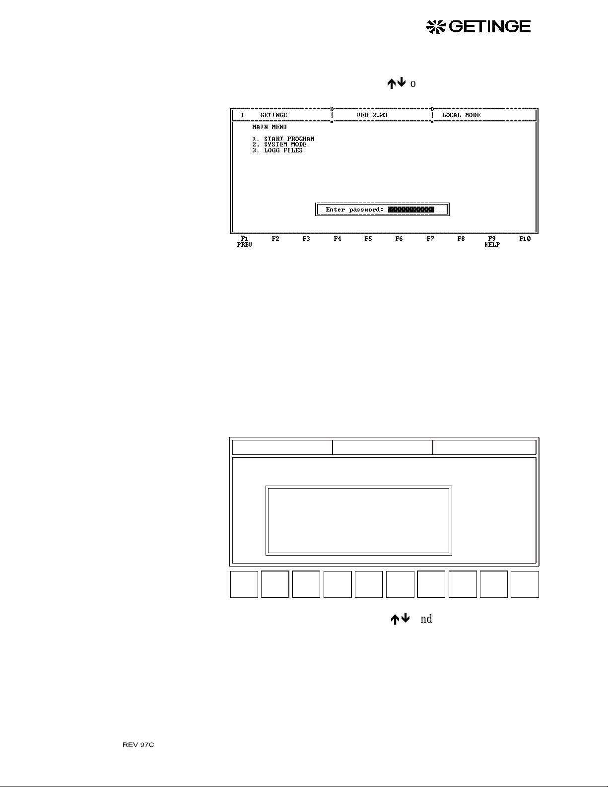
Main menu
EXIT MANUAL
Select either START PROGRA M, SYSTEM MODE or LOG FILES by
highlighting the desired text usin g
then push ENTER.
Activation of SYSTEM MODE or LOG FILE requires a password with
level 2 (service passwo r d) or hig he r. No n acc epted p asswo rd re su lt s in
a message in window 6.
ÏÐ
or typing the leading number,
Activate program
NOTE!
Item 3 LOG FILES on the menu is only available with OP H.
F1 PREV - Previous menu
F9 HELP - Help text
Activate desired prog ram , from the scrollable list.
94/02/23 08:18:17
ACTIVATE PROG RAM
PACS PROGRAM DIRECTORY
P01 PROGRAM_1
P02 PROGRAM_2
P03 PROGRAM_3
P04 PROGRAM_4
P05 PROGRAM_5
P06 PROGRAM_6
P07 PROGRAM_11
P08 PROGRAM_7
P09 PROGRAM_12
F1 F2
PREV HELP
F3
P1
P 1 PROGRAM 1
94/02/23 10:38
94/02/23 10:38
94/02/23 10:38
94/02/23 10:38
94/02/23 10:38
94/02/23 10:38
94/02/23 10:38
94/02/23 10:38
94/02/23 10:38
F4
P2
F5 F6
P3
P4 P5
STANDBY 01
F7
F8 F9
F10
NEXT
Highlight de sired program using
ÏÐ
and confirm selection wi th
ENTER.
The first five programs in the list may also be activated by pushing
F3-F7.
Activation of a program is automatically followed by PARAMETER
INPUT menu.
9
Page 10

Parameter input
EXIT MANUAL
Functio n keys:
F1 PREV - Previous menu
F3-F7 P1 - P5 - Activate first five progra ms in li st
F9 HELP - Help text
F10 NEXT - Go to PARAMETER INPUT menu without activating any
new program.
This menu will not be shown if the select ed program do es not contain
any adjustable parameter.
With PACS in stand by mode only, this menu allows for the operator to
change adjustable parameters for the previously selected progr a m.
92/09/25 08:18:17
PARAMETER INPUT
PARAMETER
STERIL TEMP
STERIL TIME
F1
BACK
F2
F3
P 1 PROGRAM 1
SET VALUE LIMIT LO
121.0
00:20:00
Enter pas sword:
F4 F5 F6
00:02:00
STANDBY 01
LIMIT HI
100.0
01:00:00
F7
F8 F9
135.0
HELP
UNIT
C
F10
NEXT
The parameter pas sword m ust be en tered to enable for an y paramet er to
be changed. If password in put is disabl ed with F1, th e parameter list can
only be scrolled through but no parameters c an be changed.
If KEY password mode is enabled, the password window never occurs
on screen. The status of the specified key input then decides whether the
parameters are allowed to be changed or just d isplayed.
Parameter inputs are checked against the high and low limits shown on
screen. Inputs beyond limits are met with a message in Window 6.
Functio n keys:
F1 BACK - Go to ACTIVATE PROGRA M menu.
F9 HELP - Help text.
F10 NEXT - Go to NORMAL PROCESS PICTURE 1 menu. If bar
code is installed, go to BATCH DE FINITION menu.
10
Page 11

Batch definition
EXIT MANUAL
Data in this menu are part of the information found in the printer log and
should be entered prior to start of a process with PACS in stand by
mode.
92/09/25 08:18:17
BATCH DEFINITION
OPERATOR:
ARTICLE:
F1
BACK
F2
F3
P 1 PROGRAM 1
F4 F5 F6
STANDBY 01
F7
F8 F9
HELP
F10
NEXT
Each input contains max imum 16 character s. Only b atch fields ha ving
field prompts de f in e d are shown in this menu. Th e ba t c h f iel d prompts,
maximum 6 fields, are defined in the PRINTER LOG DEFINITION.
If the definition prescribes field entry as a requirement, the field can not
be left without any character entered.
Function keys:
F1 BACK - Go to ACTIVATE PROGRAM menu.
F9 HELP - Help text.
F10 NEXT - Go to NORMAL PROCESS PIC.1 menu.
Normal process picture 1
This menu continuou sly displays PAC S data on screen . No data en try
possible.
Active process tim e and phase t ime are sh own on th e same li ne as the
heading.
11
Page 12

EXIT MANUAL
The left column shows the current values of the continuing process
parameters. These are parameters defined in the 15 first entries of NORMAL PROCESS PICTURE DEFINITION.
The right column shows the set values of the continuing process 15 first
A and I parameters. These will not be updated.
PACS error text is shown on the fir st half of line 25 a nd informat ion text
on remaining half.
Operator password will be prompted for on this line after a process failure.
Function keys:
F1 BACK - Go to ACTIVATE PROGRAM menu.
F2 NPIC1 - No function in this menu.
F3 NPIC2 - Go to NORMAL PROCESS PICTURE 2.
F4 EPIC - Go to ENLARGED PROCESS PICTURE.
F5 PPIC - Go to PLOT PROCESS PICTURE.
F6-F10 Name and function defined by PACS program.
Normal process picture 2
This menu continuou sly displays PAC S data on screen . No data en try
possible.
Active process tim e and phase t ime are sh own on th e same li ne as the
heading.
The left column shows the current values of the continuing process
parameters. These ar e para meters def ined in the 16 - 30 fir st entr ies of
NORMAL PROCESS PICTURE DEFINITION .
The right column shows the cu rrent values of the contin uing process
parameters. These ar e para meters def ined in the 31 - 45 fir st entr ies of
NORMAL PROCESS PICTURE DEFINITION .
PACS error text is show n on the first half of li ne 25 and inform ation
text on the remaining half.
12
Page 13

Enlarged picture
EXIT MANUAL
Function keys:
F1 BACK - Go to ACTIVATE PROGRAM menu.
F2 NPIC1 - Go to NORMAL PROCESS PICTURE 1.
F3 NPIC2 - No function in this menu.
F4 EPIC - Go to ENLARGED PROCESS PICTURE.
F5 PPIC - Go to PLOT PROCESS PICTURE.
F6-F10 Name and function defined by PACS program.
This menu continuou sly displays PAC S data on screen . No data en try
possible.
Data is displayed with enlarged character s in order to facilitate dista nt
readings.
Active process tim e and phase t ime are sh own on th e same li ne as the
heading.
Maximum 4 par am et ers can be shown in t hi s me n u. Ac t ua l p a rame te rs
are defined in ENLARGED PROCESS PICTURE DEFINITION.
PACS error text is show n on the first half of li ne 25 and inform ation
text on remaining half.
Function keys:
F1 BACK - Go to ACTIVATE PROGRAM menu.
F2 NPIC1 - Go to NORMAL PROCESS PICTURE 1.
F3 NPIC2 - Go to NORMAL PROCESS PICTURE 2.
F4 EPIC - No function in this menu.
F5 PPIC - Go to PLOT PROCESS PICTURE.
F6-F10 Name and function defined by PACS program.
13
Page 14

Plot process picture
This menu plots real time signals in a diagram on the screen.
Signal names and corresponding Y-axis are listed above the plot.
Active process and phase ti mes are shown on the same line as the
header.
EXIT MANUAL
Maximum 2 Y-axis and 6 si gn als can be disp lay ed. Si gn als and Y-axi s
are defined in the me nu PLOT PROCESS PICTURE DEFINITION.
PACS error text is shown on the fir st half of line 25 a nd informat ion text
on remaining half.
The length of the X-axis will auto matically adapt to the duration of the
active process.
Function keys:
F1 BACK - Go to ACTIVATE PROGRAM menu.
F2 NPIC1 - Go to NORMAL PROCESS PICTURE 1.
F3 NPIC2 - Go to NORMAL PROCESS PICTURE 2.
F4 EPIC - Go to ENLARGED PROCESS PICTURE.
F5 PPIC - No function in this menu.
F6-F10 Name and function defined by PACS program.
System mode menu
Highlight desired altern ative using
push ENTER.
ÏÐ
down or leading n umber then
14
Page 15

EXIT MANUAL
Activation of SYSTEM PROGRA MMING requires entering a passwords with level 4.
Calendar
92/09/25 08:18:17
SYSTEM MODE MENU
1. SYSTEM PROG RAMMING
2. CALENDAR
3. CALIBRATION
4. SERVICE
5. ERROR LOGG
6. TEST FUNCTIONS
F1
PREV
F2
F3
P 1 PROGRAM 1
F4 F5 F6
STANDBY 01
F7
F8 F9
Function keys:
F1 PREV - Previous menu.
F9 HELP- Help text.
Changing date and system time is made in this menu.
94/02/23 15:40:30
CALENDAR
P 1 PROGRAM 1
STANDBY 01
F10
HELP
DATE: 1994 / 02 / 23 YYYY / MM / DD
TIME: 15 : 40 : 30 HH : MM : SS
F1
PREV
F2
F3
F4 F5 F6
F7
F8 F9
HELP
F10
EXIT
The format of date depe nds on the way it is specif ied in the SYSTEM
CONFIGURATION menu.
Possible formats are:
SW - yy/mm/dd
US - mm/dd/yy
EU - dd/mm/yy
Ranges for time field are 00:00:00 - 23:59:59
Function keys:
F1 PREV - Abort menu and cancel setting
F9 HELP- Help text.
15
Page 16

F10 EXIT - Exit menu and activate setting
Calibration menus
Highlight desired alter native using
push ENTER.
ÏÐ
or leading number and then
EXIT MANUAL
92/09/25 08:18:17
CALIBRATION MENU
1. ANALOG I NPUT MANUAL CALIBRAT ION
2. ANALOG I NPUT AUTOMATIC CALIBRATION
3. ANALOG OUTPUT MANUAL CALIBRATION
F1
PREV
F2
F3
Function keys:
F1 PREV - Previous menu
F9 HELP- Help text.
Analog input manual calibration
The calibration const ants gain (A) an d offset (B) for analog input signals should be set in this menu.
P 1 PROGRAM 1
F4 F5 F6
STANDBY 01
F7
F8 F9
HELP
F10
92/09/25 08:18:17
ANALOG INPUT MANUAL CALIBRATION
SYMBOLIC NAME
AI00
CHAMBER TEMP
AI01
JACKET TEMP
AI02
CONTROL TEMP
AI03
PRESSURE
F1
PREV
F2
F3
F4 F5 F6
P 1 PROGRAM 1
TYPE
PT100
PT100
PT100
PRESS
UNIT
STANDBY 01
A-GAIN
F7
0.000
0.000
0.000
0.000
C
C
C
BAR
B-OFFSET
0.000
F8 F9
HELP
0.0
0.0
0.0
F10
EXIT
The number of AI shown in the scrollable list is defined by the AI-modules specified in the SYSTEM CONFIGURATION MENU. A maximum of 32 AI-channels on 10 AI-modules can be specified.
A-gain is a value between 0.000 and 9.999.
The format (unit) of the B-offset is the same as that of the actual sensor.
Input is limited to ±10% of the range of the actual, AI-sensor.
16
Page 17

Function keys:
F1 PREV - Abort menu and skip all changes
F9 HELP- Help text.
F10 EXIT - Exit menu and save changes.
Analog input automatic calibration
Selection of analog inputs
First of all the operator has to select the group of sensor to be calibrated
by highlighting these.
EXIT MANUAL
92/09/25 08:18:17
SELECT ANALOG INPUT FOR AUTO MATIC CALIBRATION
SYMBOLIC NAME
AI00
CHAMBER TEMP
AI01
JACKET TEMP
AI02
CONTROL TEMP
AI03
PRESSURE
F1
PREV
F2
F3
P 1 PROGRAM 1
TYPE
PT100
PT100
PT100
PRESS
F4 F5 F6
UNIT
STANDBY 01
CALIBRATE
C
C
C
BAR
F7
YES
YES
NO
NO
F8 F9
HELP
F10
CALIB
The number of AI shown in the scrollable list is defined of the AI-modules specified in the SYSTEM CONFIGURATION MENU. A maximum of 32 AI-channels on 10 AI-modules can be specified.
A YES in the CALIBR ATE field in dicates tha t the sensor sh ould be
included in the calibra tion. The operato r can toggle bet ween the alternatives YES / NO with the button SPACE.
Function keys:
F1 PREV - Skip changes and go back to previous menu
F9 HELP - Help text
F10 CALIB - Go to automatic calibr ation.
17
Page 18

Automatic calibration
This menu is used for automatic calibration of analog inputs.
EXIT MANUAL
92/09/25 08:18:17
ANALOG INPUT AUTOMATIC CALIBRATION
SYMBOLIC NAME
AI00
CHAMBER TEMP
AI01
JACKET TEMP
F1
PREV
F2
F3
LOW
P 1 PROGRAM 1
VALUE
135,0
121,0
F4 F5 F6
HIGH PROT
UNIT
C
C
STANDBY 01
A-GAIN
0.000
0.000
B-OFFSET
F7
0.0
0.0
F8 F9
HELP
REFERENCE
LOW 0.8
HIGH 138.2
F10
Selected sensors are listed on the screen. A maximum of 14 sensors can
be calibrated at the same t ime. Measured value and calc ulated A-gain
and B-offset are continu ously updated for selected se nsors.
Calibration steps:
A Subject the sensors to the low reference medium and wait until the
measured value is stable.
B Write the measured value in LOW REFERENCE field and push F3
to send the value to PACS .
C Subject the sensors to the high reference medium and wait until the
measured value is stable.
D Write the measured value in HIGH REFERENCE field and push F5
to send the value to PACS .
At this time, PACS calculates new gain and offset constants. Calculated constants and measured sensor values are continuously
updated on the screen.
By pushing F7, a calibration protocol is printed out. Before starting the
print out, the operator may enter his signature in a pop up window,
thereby including this signature in the protocol.
Function keys:
F1 PREV - Abort menu
F3 LOW - Send low reference to PACS
F5 HIGH - Send high reference to PACS and calculate new constants
F9 HELP- Help text.
F7 PROT - Print calibration protocol
18
Page 19

Analog output manual calibration
This menu is to set calibration constants such as gain (A) and offset (B)
for analog outputs.
EXIT MANUAL
92/09/25 08:18:17
ANALOG OUTPUT MANUAL CALIBRATION
SYMBOLIC NAME
AO00
AO01
AO02
F1
PREV
F2
F3
LOW
P 1 PROGRAM 1
F4 F5 F6
HIGH
STANDBY 01
A-GAIN
0.000
0.000
0.000
F7
B-OFFSET
0.0
0.0
0.0
F8 F9
HELP
F10
EXIT
The number of AO shown in the scrollable list is defined by the number
of AO-modules specified in the SYSTEM CONFIGURATION menu.
Each module contains 2 channels.
A maximum of 4 AO-modules, i. e. 8 channels can be specified.
A-GAIN is a value between 0.000 - 9.999
B-OFFSET is a value between 000.0 - 100.0
A-GAIN and B-OFFSET are set directly by pressing F10 when the fac-
tors have been modified.
Otherwise calibration can be made in accordance with following procedure:
A Enter A-GAIN and B-OFFSET for the channel to be calibrated.
B Mark calibration channel by placing the cursor in any field of this
line.
C Activate LOW calibration by pushing F3. On this command, PACS
will set actual AO-channel to 10.0% of maxim um output using
entered gain and offset constants.
D Activate HIGH calibrat ion by pushing F5. On this command,
PACS will set actual AO-channel to 90.0% of maximum output
using entered gain and offset constants.
E Output value will be measured. Step A - D should be repeated until
output measure is correct.
Function keys:
F1 PREV - Abort menu and skip all changes
F3 LOW - Activate low value calibration
F5 HIGH - Activate high va lu e c al i bra t i on
F9 HELP- Help text
19
Page 20

Service
EXIT MANUAL
F10 EXIT - Exit menu and save changes
This menu is to supervise the service intervals of the sterilizer. These
can be based either on time or on n umber of cycles. Ei ght of each can
be defined.
When a time or cycle limit is obtained, the SERVICE system flag SF17
is set.
Error log
92/09/25 08:18:17
SERVICE
ACTIVITY INTERVAL ACT .VAL
1.
WEEKLY SERVICE
2.
MONTHLY SERVICE
3.
3-MONTH SERVICE
4.
6-MONTH SERVICE
5.
12-MONTH SERVICE
6.
7.
8.
1.
REPLACE AIR FILT
2.
COOLER CHECK
3.
VALIDATION
4.
F1
PREV
F2
F3
LIST EXIT
P 1 PROGRAM 1
40
176
530
1056
2112
0
0
0
600
4224
0
0
14
152
506
506
506
0
0
0
112
0
0
0
F4 F5 F6
STANDBY 01
ON
ON
ON
ON
ON
OFF
OFF
OFF
ON
ON
OFF
OFF
COMMAND
F8 F9
UNIT STAUS
HOUR
HOUR
HOUR
HOUR
HOUR
HOUR
HOUR
HOUR
CYCLE
CYCLE
CYCLE
CYCLE
F7
START
--
--
--
--
--
--
RESET
--
START
--
--
--
--
--
HELP
F10
F1 PREV - Previous menu
F3 LIST - Show choice list
F9 HELP- Help text.
F10 EXIT - Exit menu and save changes
This menu displays the error log. This contains type of error, date, time
and the name of the program in which it occurred.
92/09/25 08:18:17
ERROR LOGG
ERROR DATE
1
TEMP SENS. ERROR
2
3
4
5
6
7
8
9
10
F1
PREV
F2
F3
P 1 PROGRAM 1
93/12/13
F4 F5 F6
STANDBY 01
TIME
13:22:10
F7
PRINTSTORE
PROGRAM
UTENSILS
F8 F9
F10
HELP
The error log cont ains information about th e latest 20 errors. This
means that the oldest message is erased each time a ne w error message
is stored.
20
Page 21

Function keys:
F1 PREV - Previous menu
F2 STORE - Store error log on file
F7 PRINT - Print error log
F9 HELP - Help text
Test function menus
Test function menu.
EXIT MANUAL
Analog input test
92/09/25 08:18:17
TEST FUNCTION MENU
1. TEST ANALO G INPUT
2. TEST ANALO G OUTPUT
3. TEST DIG ITAL INPUT
4. TEST DIG ITAL OUTPUT
5. TEST USER FLAG
6. TEST SYST EM FLAG
7. TEST PICTURE DIGITAL
8. TEST PRINT ER
9. TEST LED
F1
PREV
Use
F2
F3
ÏÐ
to highlight your choice, then push ENTER.
P 1 PROGRAM 1
F4 F5 F6
STANDBY 01
F7
F8 F9
HELP
F10
Function keys:
F1 PREV - Previous menu
F9 HELP - Help text
This menu shows all defined analog inputs in two columns on screen.
Actual values are continuously updated.
92/09/25 08:18:17
TEST ANALOG INPUT
AI00 CHAMBER TEMP
AI01 JACKET TEMP
AI02 CONTROLTEMP
AI03 PRESSURE
F1
PREV
F2
F3
P 1 PROGRAM 1
120.9 C
121.5 C
118.7 C
1.058 BAR
F4 F5 F6
Function keys:
F1 PREV - Previous menu
STANDBY 01
F7
F8 F9
F10
21
Page 22

Analog output test
The operator is, by setting the mode to MANUAL, disabling
the built in safety system!
Make sure beyond all doubts that it is safe to set the output
to manual mode before doing it.
In this menu, analog outputs can be set to desired values.
Actual values are continuously updated.
EXIT MANUAL
92/09/25 08:18:17
TEST ANALOG OUTPUT
SYMBOLIC NAME
AO00
AO01
F1
PREV
F2
F3
P 1 PROGRAM 1
MODE
AUTO
MANUAL
F4 F5 F6
STANDBY 01
SET
VALUE %
F7
0.0
0.0
F8 F9
SEND
0.0
0.0
HELP
F10
EXIT
In AUTO mode the output is controlled by the PACS program
In MANUAL mode the output can be set to desired v a lue.
The number of AO shown in scrollable form is defined of how many
AO-modules are specified in SYSTEM CONF IGURATION menu.
Each module contains 2 channels. A maximum of 4 AO-modules can be
specified i. e. 8 channels.
MODE fields specify whether the output is in AUTO or MANUAL
mode. Operator can, when in these fields, toggle between the two alternatives using the SPACE bar.
In the SET field the operator can specify the value to which the output
should be set. Limits for the value field is 0.0 - 100.0%. Note that MANUAL mode must be selected, otherwise SET will be ignored by PACS.
With F8 entered values can be sent to PACS without leaving this menu.
Function keys:
F1 PREV - Abort test.
F8 SEND - Send entered values and mode to PACS.
F9 HELP - Help text
22
Page 23

Digital input test
EXIT MANUAL
F10 EXIT - Send entered valu es a nd mode to PACS and exit menu.
Remember to reset the mode to AUTO before leaving the
menu.
This menu shows all define d digi tal inpu ts in three c olu mns on scr een.
Actual values are continuously updated.
92/09/25 08:18:17
TEST DIGITAL INPUT
DI00 SYMBOLIC NAME 0
DI01 SYMBOLIC NAME 1
DI02 SYMBOLIC NAME 0
DI03 SYMBOLIC NAME 1
DI04 SYMBOLIC NAME 1
F1
PREV
F2
F3
P 1 PROGRAM 1
F4 F5 F6
Function key:
F1 PREV - Previous menu
STANDBY 01
F7
F8 F9
F10
23
Page 24

Digital output test
The operator is, by setting the mode to MANUAL, disabling
the built in safety system!
Make sure beyond all doubts that it is safe to set the output
to manual mode before doing it.
In this menu, digital outp uts can be set to desired status.
Actual values are continuously updated.
EXIT MANUAL
92/09/25 08:18:17
TEST DIGI TAL OUTPUT
SYMBOLIC NAME
DO00
DO01
DO02
DO03
DO04
DO05
DO06
F1
PREV
F2
F3
P 1 PROGRAM 1
MODE
AUTO
AUTO
AUTO
AUTO
AUTO
AUTO
AUTO
F4 F5 F6
SET
0
0
0
0
0
0
0
STANDBY 01
STATUS
1
0
1
1
0
0
0
F7
F8 F9
SEND
HELP
F10
EXIT
In AUTO mode the output is controlled by the PACS program.
In MANUAL mode the output can be set to desired st atus.
The number of DO sho wn i n scr ollab le fo rm is d efi ned of the numbe r
of DO-modules specifi ed in SYSTEM CONFIGURATI ON menu. Each
module contains 8 channels. A maxim um of 8 DO-modules can be
specified i. e. 64 channels.
MODE fields specify whether the output is in AUTO or MANUAL
mode. Operator can, when in this field, toggle between the two alternatives using the SPACE bar.
In the SET fields the operator specifies the output statu s. Operator
can, when in these fields and in MANUAL mode, toggle between 0 and
1 using the SPACE key
With F8 entered status can be sent to PACS without leaving this menu.
Function keys:
F1 PREV- Abort test.
F8 SEND - Send entered values and mode to PACS.
F9 HELP - Help text
24
Page 25

Test user flag
EXIT MANUAL
F10 EXIT - Send entered valu es a nd mode to PACS and exit menu.
Remember to reset the mode to AUTO before leaving the
menu.
This menu shows all defined user flags in a scrollable list on screen.
Actual values are continuously updated.
Test system flag
92/09/25 08:18:17
USER FLAG TEST PICTURE
SYMBOLIC NAME
UF000
UF001
UF002
UF003
UF004
UF005
UF006
UF007
F1
PREV
F2
F3
P 1 PROGRAM 1
STATUS
0
0
0
0
0
0
0
0
F4 F5 F6
STANDBY 01
F7
F8 F9
HELP
F10
Function key:
F1 PREV - Previous menu
F9 HELP - Help text
This menu shows all defined system flags in a sc rollable list on screen.
Actual values are continuously updated.
92/09/25 08:18:17
SYSTEM FLAG TEST PICTURE
SYMBOLIC NAME
SF000 INT I2C ERROR
SF001 OP1 I2C ERROR
SF002 OP2 I2C ERROR
SF003 OP31 COM ERROR
SF004 OP32 COM ERROR
SF005 OP33 COM ERROR
SF006 PRINT CO M ERROR
SF007 AUX COM ERROR
F1
PREV
F2
F3
P 1 PROGRAM 1
F4 F5 F6
Function key:
F1 PREV - Previous menu
F9 HELP - Help text
STATUS
0
0
0
0
0
0
0
0
STANDBY 01
F7
F8 F9
HELP
F10
25
Page 26

Test picture
EXIT MANUAL
This menu shows the status of all d igital in puts and ou tputs in th e system. Status are continuously updated.
Test printer
92/09/25 08:18:17
DIGITAL TEST PICTURE
DI MOD 0
DO MOD 0
DO MOD 1
F1
PREV
F2
F3
P 1 PROGRAM 1
00000000 7input
00000000 7output
00000000 15
F4 F5 F6
STANDBY 01
F7
F8 F9
F10
The number of shown D I / DO modules are specified in SYSTEM
CONFIGURATION menu.
Function key:
F1 PREV - Previous menu
This menu sends test strings to connected printer.
Test LED
92/09/25 08:18:17
TEST PRINTER
Strings sent to printer:
PRINTER TEST FOLLOWS
!"#$%&'()*+,-./0123456789:;<=>?@ABCDEFG
HIJLKMNOPQRSTUVWXYZ[]^_`abcdefghijklmno
pqrstuvwxyz<|>~
Press <Enter> to continue <F1> to abort.
F1
PREV
F2
F3
P 1 PROGRAM 1
F4 F5 F6
STANDBY 01
F7
F8 F9
F10
Shown test str ings are sent to prin ter by pressing ENTER. Test is
aborted with F1.
Function key:
F1 PREV - Previous menu
When this menu is activated, a command is sent to PACS.
On this command, PACS makes all LED’s flash for about 5 seconds on
all connected operat ing panels.
26
Page 27

Log-files (OP H only)
This menu handles the log-fi le functions. the O P H program can store
log-files from connected sterilizers on separate files.
Highlight desired alt ernative using the a rrow-keys or simply ent er the
leading digit an d pre ss ENTER.
Function key:
F1 PREV - Previous menu
EXIT MANUAL
Print log-file
Display log-file
Print the selected log-file on a printer connected to the PC.
Highlight desired sterilizer number using the arrow-keys and press
ENTER.
Select the log-file to be printed and press ENTER.
Function key:
F1 PREV - Previous menu
The selected file is displayed on screen.
Highlight desired sterilizer number using the arrow-keys and press
ENTER.
Select the log-file to be shown and press ENTER.
Function keys:
F1 PREV - Previous menu
F6 BACK - Previous page of the log -fi l e
F7 NEXT - Next page of the log-file
Copy log-file
The selected log-file is copied to disk and directory as decided.
Highlight desired sterilizer number using the arrow-keys and press
•
ENTER.
27
Page 28

Delete log-file
EXIT MANUAL
•
Select the log-file to be copied an d press ENTER.
•
Specify the path and press F10 to copy the file.
Function keys:
F1 PREV - Previous menu
F10 EXIT - Copy the fi le and leave menu
A previously copied log-file is deleted.
Highlight desired sterilizer number using the arrow keys and press
ENTER.
Select the log-file to be deleted and press ENTER.
Note! Only files that have been copied can be deleted.
Function keys:
F1 PREV - Previous menu
Plot log-file
The log-file may be plotted on screen in almost the same way as is
described under heading ”PLOT PROCESS PICTURE”. The difference
is that the plot is not d epending on settings made in ”PLOT PROCESS
PICTURE DEFINITION” but on settings made in this menu.
Highlight desired sterilizer number using the arrow keys and press
ENTER.
Select the log-file to be plotted and press ENTER.
Definition:
The plot picture can contain up to six signals and two y-axis.
Y-AXIS DEFINITION
Two Y-axis can be defined, A and B. An Y-axis is defined by unit, low
value and high value.
Unit is specified via a choice list where t he operator can choose
between C/F, BAR/kPa/PSI, % and F0. The unit for temperature and
28
Page 29

EXIT MANUAL
pressure is depending on selections made in the SYSTEM CONFIGURATION menu.
Formats and limits for high and low values are determined by the
active unit.
UNIT FORMAT RANGE
C xxx.x 0.0 - 999.9
F xxx.x 0.0 - 999.9
BAR x.xxx 0.000 - 9.999
kPa xxx.x 0.0 - 999.9
PSI xx.xx 0.00 - 99.99
% xxx.x 0.0 - 100.0
F0 xxx.x 0.0 - 999.9
Print summary
An Y-axis is as activated if the value in high is greater than that in
low. If Y-axis A i s no t a c t iv a ted it wi l l n ot be sh ow n. If Y-axis B is not
activated it is shown unmarked.
PLOT SIGNAL DEFINITION
Process picture signals are specified via a two step choice list where the
operator can c hoose b etw een d efi ned AI, AO , F0, C P, DF an d TP fu nctions.
Y-AXIS defines which Y-ax is a signal is related to. The operator can
toggle between the alternatives A/B with SPACE when in thes e fi elds.
Function keys:
F1 PREV - Abort menu and skip all changes
F3 LIST - Show choice list
F5 CLEAR - Clear active field
F9 HELP - Help text
F10 EXIT - Exit menu and save changes
An abstract co ntaini ng the info rmation l isted be low is se nt to th e printer
connected to the PC.
•
Header
•
All phase shifts accompanied with a log.
•
All errors together with log.
29
Page 30

Log-file definition
EXIT MANUAL
This menu manages the definition of the log-file. Up to 20 sterilizers
may be defined.
PACS ID is the unique nu mber of the steri lizer as set in th e SYSTEM
CONFIGURATION MENU.
LOG-PATH describes the full way to the direct ory wher e the log- file is
to be stored.
The following steps has to be taken before logging can be star ted.
•
OP33 in SYSTEM CONFIGURATION MENU set on.
•
System flag SF29 PC DISK LOG set.
The file name is composed in the following way :
<STERILIZER No:><MONTH><DAY><RUNNIN G No .>.LOG
Function keys:
F1 PREV - Abort menu and skip all changes
F5 CLEAR - Clear active field
F9 HELP - Help text
F10 EXIT - Exit menu and save changes
30
Page 31

Technical data
PACS 2000 Ver. 2.0
Adaptation to line voltage by means of transformer 2 * 18 ±10% VAC,
50 - 60 Hz
Power consumptio n depending on the degr ee of extension < 100 VA
o
Operating ambient temperature +10 - +60
C
EXIT MANUAL
Humidity resistance control system
front panels
Water and dust protection of control system
front panel
Electromagnetic compatibility FCC 15 J, CIS PR22,
PC board performance according to CSA and UL
Maximum distanc e between operator panel and control unit 10 m
System sampli ng rate for all in- and outputs 4 Hz
Type of digital input s supplied from system Opto-coupled 24 V DC
Number of digital input modules Maximum 8
Number of inputs with each mo dule 8
Type of digital outputs Relays, contact rating
Number of digital output modules Maximum 8
90% rel.
100% rel.
IP43
IP65
EN 50081, EN 50082 ,
IEC 801
12 A
Number of digital outputs with each module 8
Number of analog input modules Maximum 10
Number of analog inputs.- PACS 2000 alone
if PACS Supervisor is
connected
Number and kind of analog inputs with module type: 1. 3 RTD Pt100
2. 3 thermocouple type K
3. 6 RTD Pt100
Maximum 32
Maximum 24
1 pressure
1 pressure
31
Page 32

Analog inputs ty pe : A. Temperature
EXIT MANUAL
4. 6 thermocouple type K
5. 2 RTD Pt100
2 pressures
6. 4 general purpose
0 - 20 mA
0 - 5 V
0 - 10 V
4 - 20 mA
*1
Sensor
Resolution
Inaccuracy
Range
B. Temperature
Sensor
Resolution
Inaccuracy
Range
C. Temperature
Sensor
Resolution
Inaccuracy
Range
Pt100 4-wire only
o
0.1
C
o
C
±0.1
-5 - +150
o
C
TC type K,
Chromel-Alumel
o
0.1
C
o
±0.2
C
-5 - +150
o
C
TC type K,
Chromel-Alumel
o
0.2
C
o
C
±0.4
-5 - +800
o
C
D. Pressure
Sensor
Resolution
Inaccuracy
Range
Wheatstone bridge
0 - 500 mV/v
0.001 bar(a)
±0.01 bar(a) for 0 - 1
bar(a) ± 1% of a ct ual
value for 1 - 5 bar(a)
0 - 5 bar(a)
32
Page 33

E. Pressure
EXIT MANUAL
Sensor
Resolution
Inaccuracy
Range
F. General purpose
Sensor
Inaccuracy
Range
G. Scale
Sensor
Wheatstone bridge
0 - 300 mV/v
0,001 bar(a)
±0.001 bar(a)
0 - 1.5 bar(a)
0 - 20 mA, 4 - 20 mA
0 - 5 V, 0 - 10 V
0.1% of span
As above
0 - 20 mA, 4 - 20 mA
0 - 5 V, 0 - 10 V
*1
*1
,
,
Inaccuracy
Range
0.1% of span
0 - 500 kg
H. Concentration
Sensor
0 - 20 mA, 4 - 20 mA
0 - 5 V, 0 - 10 V
Inaccuracy
Range
0.1% of span
0 - 1200 mg/l
Analog outputs 0 - 20 mA, 4 - 20 mA,
0 - 5 V, 0 - 10 V
Resolution 0.4%
Activation rate 4 Hz
Number of analog output modules Maximum 4
Number of analog outputs with each module 2
*1. All four inputs on the module will be set for 4 - 20 mA when this alternative is used.
*1
,
33
 Loading...