

Page 1
BariAir Therapy System
USER MANUAL
P/N 404832-AH Rev A • 06/2014
0086
...with people in mind
Page 2

Page 3

CAUTION
ARJOHUNTLEIGH HEREBY DISCLAIMS ALL EXPRESS OR IMPLIED WARRANTIES, INCLUDING WITHOUT LIMITATION ANY
IMPLIED WARRANTY OF MERCHANTABILITY OR FITNESS FOR A PARTICULAR PURPOSE, ON THE ARJOHUNTLEIGH
PRODUCT(S) DESCRIBED IN THIS PUBLICATION. ANY WRITTEN WARRANTY OFFERED BY ARJOHUNTLEIGH SHALL
BE EXPRESSLY SET FORTH IN THIS PUBLICATION OR INCLUDED WITH THE PRODUCT. UNDER NO CIRCUMSTANCES
SHALL ARJOHUNTLEIGH BE LIABLE FOR ANY INDIRECT, INCIDENTAL, OR CONSEQUENTIAL DAMAGES AND EXPENSES,
INCLUDING DAMAGES OR INJURY TO PERSON OR PROPERTY, DUE IN WHOLE OR IN PART TO THE USE OF THE
PRODUCT OTHER THAN THOSE FOR WHICH DISCLAIMER OF WARRANTY OR LIMITATION OF LIABILITY IS EXPRESSLY
PROHIBITED BY SPECIFIC, APPLICABLE LAW. NO PERSON HAS THE AUTHORITY TO BIND ARJOHUNTLEIGH TO ANY
REPRESENTATION OR WARRANTY EXCEPT AS SPECIFICALLY SET FORTH IN THIS PARAGRAPH.
Descriptions or specifications in ArjoHuntleigh printed matter, including this publication, are meant solely to
generally describe the product at the time of manufacture and do not constitute any express warranties except as set
forth in the written limited warranty included in this publication or with this product. Information in this publication
may be subject to change at any time. Contact ArjoHuntleigh for updates.
Important Information For Users
In order for ArjoHuntleigh products to perform properly, ArjoHuntleigh recommends the following conditions. Failure
to comply with these conditions will void any applicable warranties.
• Use this product only in accordance with these instructions and applicable product labeling.
• Assembly, operations, extensions, re-adjustments, modifications, technical maintenance or repairs must
be performed by qualified personnel authorized by ArjoHuntleigh. Contact ArjoHuntleigh for information
regarding maintenance and repair.
• Ensure the electrical installation of the room complies with the appropriate national electrical
wiring standards.
Specific indications, contraindications, warnings, precautions and safety information exist for ArjoHuntleigh’s
therapeutic support surface products. It is important for users to read and familiarize themselves with these
instructions and to consult the treating physician prior to patient placement and product use. Individual patient
conditions may vary.
NOTICE
This product has been configured from the manufacturer to meet the specific voltage requirements. Refer to the
product information label for specific voltage.
Page 4

Page 5

TABLE OF CONTENTS
Introduction
Indications ..........................................................................................................................................................................................1
Contraindications ...........................................................................................................................................................................2
Risks and Precautions ...................................................................................................................................................................2
Safety Information .........................................................................................................................................................................2
Patient Placement
Preparation for Patient Placement ....................................................................................................................................... 5
Patient Transfer to the BariAir Therapy System ...............................................................................................................6
Air Pressure Adjustment .............................................................................................................................................................8
Turn Assist Adjustment ...............................................................................................................................................................9
Pulsation Adjustment ...............................................................................................................................................................10
Percussion Adjustment ............................................................................................................................................................10
Completion of Patient Placement .....................................................................................................................................10
Nursing Care
Cardiopulmonary Resuscitation (CPR) ...........................................................................................................................12
Auxiliary CPR ................................................................................................................................................................................... 12
Alarms ................................................................................................................................................................................................. 13
Q-Shift Check ................................................................................................................................................................................. 13
Patient Enter / Exit Via Foot of Bed (Ambulatory Patients).................................................................................14
Patient Transfer to Bed (Non-Ambulatory Patients) ............................................................................................... 14
Installation of Extension Packs / Cushions ................................................................................................................... 15
Footboard Release for Taller Patients and Traction ................................................................................................. 16
Bed Adjustment to Cardiac Chair Position...................................................................................................................16
Page 6

Patient Transport in Cardiac Chair Position .................................................................................................................17
Side Rail Operations ................................................................................................................................................................... 18
• Side Rail Positions .................................................................................................................................................................18
• Adjust Side Rail to Narrow Door Position ...............................................................................................................18
• Side Rail Operating Tips ....................................................................................................................................................18
Extension Cushion Operations ...........................................................................................................................................19
• Extension Board Positions................................................................................................................................................19
• Adjust Extension Packs and Cushions to Normal Position .......................................................................... 19
Adjustable Corner Post Operations ..................................................................................................................................19
• Adjustable Corner Post Positions ................................................................................................................................ 19
• Set Adjustable Corner Post to Normal Position..................................................................................................19
Skin Care............................................................................................................................................................................................19
Incontinence / Drainage ......................................................................................................................................................... 19
Patient Bathing ..............................................................................................................................................................................20
Bedpan Placement ..................................................................................................................................................................... 20
Bedpan Removal .......................................................................................................................................................................... 21
Patient Positioning ......................................................................................................................................................................21
• Right Hold ..................................................................................................................................................................................21
• Center Hold ..............................................................................................................................................................................21
• Left Hold ..................................................................................................................................................................................... 22
• Trendelenburg / Reverse Trendelenburg ...............................................................................................................22
• Cardiac Chair ............................................................................................................................................................................ 22
General Operation ...................................................................................................................................................................... 22
Care and Cleaning
Daily Care and Cleaning of the BariAir Therapy System While In Use ........................................................... 23
Weekly Care and Cleaning of the BariAir Therapy System While In Use ...................................................... 24
Preventive Maintenance .........................................................................................................................................................24
Page 7

Operating Instructions
Power-Up Procedure .................................................................................................................................................................24
Main Control Panel .....................................................................................................................................................................25
• Home Menu ............................................................................................................................................................................. 25
- InstaFlate Function ............................................................................................................................................................26
- Seat Deflate ..........................................................................................................................................................................26
- Main Menu ............................................................................................................................................................................ 27
• Turn Assist Menus .......................................................................................................................................................... 27
• Pulsation Menu ............................................................................................................................................................... 28
• Height / Weight Preset ...............................................................................................................................................29
• Percussion Menus .........................................................................................................................................................30
• Right Hold .......................................................................................................................................................................... 31
• Center Hold ....................................................................................................................................................................... 31
• Left Hold .............................................................................................................................................................................. 31
• Lock-Out Menu ............................................................................................................................................................... 32
- Status Menu ......................................................................................................................................................................... 33
• Air Pressures Display ............................................................................................................................................................34
• Alarm Silence ........................................................................................................................................................................... 34
• Scale Menu................................................................................................................................................................................35
- Zero............................................................................................................................................................................................35
- Preset ........................................................................................................................................................................................36
- Alarm ........................................................................................................................................................................................36
- Weight Hold .........................................................................................................................................................................37
- Delay ......................................................................................................................................................................................... 37
- Store Trend ............................................................................................................................................................................38
- Weight Trend Chart .......................................................................................................................................................... 38
Page 8

• CPR ................................................................................................................................................................................................. 38
• Auxiliary CPR
Transport Mode ............................................................................................................................................................................ 39
Hand Control
Power Down Procedure ..........................................................................................................................................................41
Specifica
Electromagnetic Compatibility (EMC)
Definition of
Customer Contact
tions
...............................................................................................................................
...............................................................................................................................
...............................................................................................................................
..................................................................................................................... 44
Symbols Used ...............................................................................................................................
Informa
tion
...............................................................................................................................
.............................................39
................................................... 40
............................................... 42
..............48
...... 48
Page 9

INTRODUCTION
The BariAir™ Therapy System is a risk management treatment system designed for large and / or difficult-to-manage
patients. The BariAir Therapy System provides low air-loss pressure management therapy, pulsation, percussion, Turn
Assist, flexible patient positioning capabilities and built-in scales for patients weighing 300* to 850 lb ([136* - 386 kg]
including accessories).
Turn Assist ‑ The continuous lateral turn up to 20˚ helps reposition the patient, promote comfort and shift pressure
points. Turn Assist is programmable with three levels of turning on each side (low, medium and high turn) as well as
pause and hold functions to suspend the patient on either side for ease in nursing care.
Pulsating Air Suspension Therapy ‑ The gentle pulsating action provides patients with one of the most aggressive
therapies available for the treatment of pressure ulcers and wounds, having been shown to increase capillary blood
flow and lymphatic drainage, while the air support surface helps reduce interface pressures. Pulsation therapy can
be customized with programmable intensities and cycle times and can be used in conjunction with Turn Assist and
percussion therapy, or as a stand-alone therapy.
Percussion Therapy ‑ Percussion therapy can be used in conjunction with Turn Assist, during turning, to help mobilize
pulmonary secretions. Percussion therapy can be customized by adjusting frequency, intensity and duration of therapy.
The BariAir Therapy System is made up of a patient support surface comprised of 23 low air-loss cushions positioned over
a pair of inflatable turning bladders, all of which are mounted on a critical care frame. The patient rests on the patient
support surface as air pressures in every other cushion slowly increase and decrease, creating a gentle pulsating action.
The cushions are grouped into three sections: head, body, and leg, allowing for customization of air pressures in each
section of cushions. When Turn Assist is activated, the bladders located beneath the cushions will slowly inflate and
deflate, turning the patient in a gentle side-to-side motion. A percussion cushion is installed beneath the low air-loss
cushions to provide chest physiotherapy.
The following accessories are available for use with the BariAir Therapy System:
• foot extension with cushion and cover sheet - increases bed length by 12 in (30 cm), useful for patients taller
than 6 ft 2 in (1.9 m)
• extension packs to provide pressure management for wide patients
• trapeze for patient positioning
Indications
The BariAir Therapy System is indicated to aid in:
• Patients whose body weight and size pose a significant risk or care management issue to the patient or staff during
the performance of routine nursing care.
• Large patients weighing between 300* and 850 lb (136* - 386 kg) including accessories.
• Large patients who are difficult to turn.
• Preventing and treating pressure ulcers.
• Large patients requiring percussion therapy.
*Certain circumstances such as patient weight or special patient care needs may warrant the use of this product for patients weighing less than 300 lb (136 kg).
1
Page 10

Contraindications
Patient conditions for which the BariAir Therapy System is contraindicated include:
• unstable cervical, thoracic and / or lumbar fracture
• cervical and skeletal traction
• total weight in excess of 850 lb (386 kg, including accessories)
Risks and Precautions
Transfer - Precaution should be taken during patient transfer, including the locking of caster brakes and caster
steering (see Patient Transfer under Patient Placement section).
Side Rails and Restraints - WARNING: Use of restraints, including side rails, can be critical to patient safety. Serious
injury or death can result from the use (potential entrapment) or non-use (potential patient falls) of side rails or other
restraints. See related Safety Information.
Patient Restraints ‑ Patient restraints may not be used with this bed.
Patient Migration ‑ Specialty surfaces have different shear and support characteristics than conventional surfaces
and may increase the risk of patient movement, sinking and / or migration into hazardous positions of entrapment
and / or inadvertent bed exit. While the BariAir Therapy System footboard can gradually release under loads, patients
may slide out of bed over the footboard, potentially risking serious injury. Such risks are increased if the head of the
bed is elevated or if the footboard has been manually released. Monitor patients frequently to guard against
patient entrapment.
Electromagnetic Interference - Although this equipment conforms with the intent of the directive 89/336/EEC
in relation to electromagnetic compatibility, all electrical equipment may produce interference. If interference is
suspected, move equipment away from sensitive devices or contact the manufacturer.
Shock Hazard ‑ Electrical shock hazard, do not remove covers. Refer to qualified service personnel.
Releasing the Footboard ‑ In some instances, releasing the footboard may increase risk of injury by making it easier
for the patient to slide out of the bed, over the footboard and onto the floor.
Safety Information
General Protocols ‑ Follow all applicable safety rules and institution protocols concerning patient and caregiver
safety.
Skin Care ‑ Monitor skin conditions regularly, particularly at bony prominences and in areas where incontinence and
drainage occur or collect, and consider adjunct or alternative therapies for high acuity patients. Early intervention
may be essential to preventing serious skin breakdown.
Brakes ‑ Caster brakes should always be locked once the bed is in position.
Bed Height ‑ To minimize the risks of falls or injury the bed should always be in the lowest practical position when
the patient is unattended. Make sure the area under and around the bed frame is clear of objects, persons and parts
of body before adjusting height.
Side Rails / Patient Restraints ‑ Whether and how to use side rails or restraints is a decision that should be based
on each patient’s needs and should be made by the patient and the patient’s family, physician and caregivers, with
facility protocols in mind. Caregivers should assess risks and benefits of side rail / restraint use (including entrapment
and patient falls from bed) in conjunction with individual patient needs, and should discuss use or non-use with
patient and / or family. Consider not only the clinical and other needs of the patient but also the risks of fatal or
serious injury from falling out of bed and from patient entrapment in or around the side rails, restraints or other
2
Page 11

accessories. In the US, for a description of entrapment hazards, vulnerable patient profile and guidance to further
reduce entrapment risks, refer to FDA’s Hospital Bed System Dimensional and Assessment Guidance To Reduce
Entrapment. Outside the US, consult the local Competent Authority or Government Agency for Medical Device Safety
for specific local guidance. Consult a caregiver and carefully consider the use of bolsters, positioning aids or floor
pads, especially with confused, restless or agitated patients. It is recommended that side rails (if used) be locked in the
full upright position when the patient is unattended. Make sure a capable patient knows how to get out of bed safely
(and, if necessary, how to release the side rails) in case of fire or other emergency. Monitor patients frequently to
guard against patient entrapment.
It is recommended that electrically operated beds conform to IEC 60601-2-38. Medical Electrical Equipment Part 2:
particular requirements for the safety of electrically operated hospital beds.
NOTE: Side rails must be in the full upright and locked position before activating turn assist.
Exit Alarm ‑ Activation of the bed exit alarm is recommended whenever a patient is unattended. Be sure to
reactivate the bed exit alarm each time the patient returns to bed.
Ambulatory Patient Entrance / Exit ‑ Caregiver should always aid patient in exiting the bed. Lower the patient
surface completely during assisted patient entrance and exit. With caregiver assistance, ambulatory patients should
always use the patient exit button to properly position the bed and then exit at the foot of the bed.
Full Trendelenburg ‑ Use full Trendelenburg to shift patient weight back and ensure against sliding when the
footboard is released or when the head is elevated. The bed will automatically move into Trendelenburg as the head
is raised.
Adjust Side Rails to Narrow Door Position ‑ After narrow door passage, reposition the side rails to full up position
unless decision has been made to not use side rails.
Extension Pack Clip Engagement ‑ When extension packs are used, ensure that the clip at the bottom of each
extension pack fully engages side rail shaft.
I.V. and Drainage Tubes ‑ Tubes should always have slack for Turn Assist and other patient movements.
Blank Display ‑ If the main control panel remains blank, call for service immediately. In the interim, use auxiliary
bed controls (including CPR) in absence of facility protocol. Auxiliary controls are located in the head end of the base
cover, on the patient’s right side.
Fluids ‑ Avoid spilling fluids on bed controls. If spills do occur, unplug the unit and clean fluid from the bed wearing
rubber gloves to avoid any possibility of shock. Once fluid is removed, plug the power cord into a wall outlet and
check operation of components in area of spill.
NOTE: Fluids remaining on controls can cause corrosion, which may cause components to fail or operate erratically,
possibly producing potential hazards for patient and caregiver.
Lock Outs ‑ Lock out of therapy functions and air functions from the main control panel and lock out of bed
functions by the service switches should be used at the staff’s discretion to ensure against unauthorized tampering
with system settings.
Moving Parts ‑ Powered bed mechanisms can cause serious injury. Keep all equipment, tubes and lines, loose
clothing, hair and parts of the body away from moving parts and pinch points.
3
Page 12

Power Cord ‑ Ensure the power cord is kept free from all pinch points and moving parts and is not trapped under
casters nor covered with rugs or carpets. Visually inspect the cord for signs of damage or wear. Improper handling of
the power cord can cause damage to the cord, which may produce risk of fire or electric shock. When transporting or
disconnecting power cord, be sure to wrap the cord in a safe position free from moving parts.
Scale Readings - Scales / patient weights are for reference only. Scale readings should not be relied upon for
medication dosage.
Hospital Grade Power ‑ Unstable electrical ground may exist. Grounding reliability can only be achieved when
the power cord is connected to an equivalent receptacle marked Hospital Grade. Where the integrity of the external
protective conductor in the installation or its arrangement is in doubt, equipment should be operated temporarily
from its battery.
Avoid Fire Hazards ‑ To minimize risk of fire, connect the bed’s power cord directly into a wall-mounted outlet. Do
not use extension cords or multiple outlet strips.
Tobacco Smoke and Other Contaminates ‑ Please follow laundering and cleaning procedures described in
the Preventive Maintenance section of the Care and Cleaning chapter of this manual in order to help decrease
tobacco smoke build-up. It is recommended that no smoking occur in, on or around bed environment, so as to avoid
build-up. Severe air restrictions (whatever the cause), may cause the unit to overheat and automatically deactivate.
Batteries ‑ Bed contains batteries and must be plugged in when not in service.
Service Personnel ‑ Inspect batteries monthly. Batteries more than 28 months old from the date of manufacture are
replaced in pairs. Install a battery history label on the battery cover with proposed date of next battery replacement.
Apply the label in a visible location so that all information is displayed.
Disposal ‑ At the end of useful life, dispose of waste according to local requirements or contact the manufacturer for
advice. There may be special requirements for disposal of batteries, leaded foam and angle sensors (if present in this
product).
Oxygen Use ‑ Unplug pendant hand control and do not use wireless pendant when using oxygen. Use of hand
controls in an oxygen-enriched environment may produce potential of fire hazard. This equipment is not suitable for
use in the presence of a flammable anesthetic mixture with air, with oxygen or with nitrous oxide.
CAUTION: When using half-bed length type oxygen administering equipment, ensure that side rails are
outside of oxygen tent and not contained within the oxygen environment.
4
Page 13
PATIENT PLACEMENT
It is recommended that all sections of this manual be reviewed prior to product use. Carefully review the
Indications, Contraindications, Risks and Precautions, and Safety Information sections in the Introduction
chapter prior to patient placement on the BariAir Therapy System.
Preparation for Patient Placement
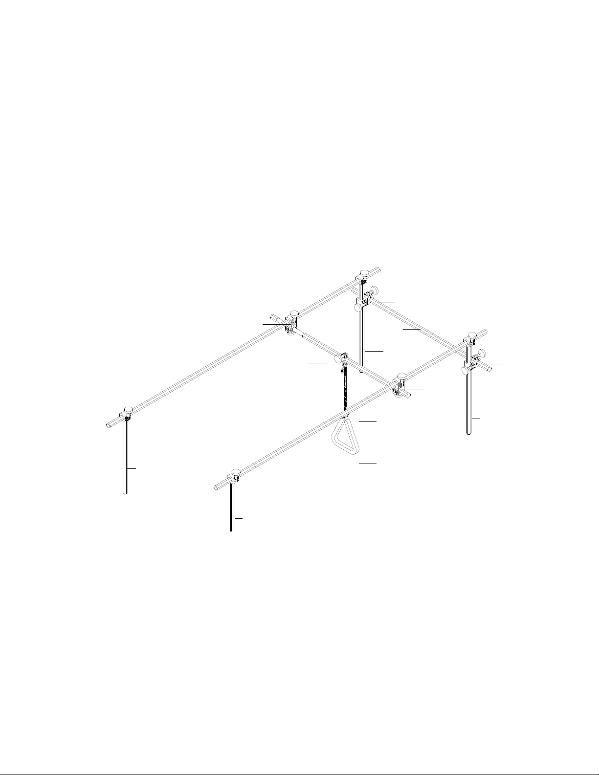
1. If an overhead rail system is required for the patient, install trapeze as follows:
NOTE: When properly installed, trapeze assembly is designed to support trapeze for patients weighing up to 850 lb
(386 kg); however, do not place more than 350 lb (159 kg) static weight directly on trapeze.
• Set adjustable corner posts to normal position.
• Insert the 22.5 in (57 cm) swivel clamp bar into I.V. pole insert behind main control panel, as shown below:
Head
of Bed
Double
Swivel Clamp
Double
Cross Clamp
48 in
Plain Bar
Foot
of Bed
22.5 in
Swivel Clamp Bar
27 in Swivel
Clamp Bar
Sliding Bar
27 in
Swivel Clamp Bar
Double
Swivel Clamp
96 in
Plain Bar
Hand Grip
Double
Cross Clamp
27 in Swivel
Clamp Bar
• Insert a 27 in (68.5 cm) swivel clamp bar into the remaining three I.V. pole inserts.
• Install double cross clamps onto swivel clamp bars at the head of the bed. Finger-tighten clamp
approximately one foot from top of each bar.
• Insert the 48 in (122 cm) plain bar into clamps on swivel clamp bars at the head of the bed. The ends of the
swivel clamp bar should extend approximately the same length beyond each clamp. Finger-tighten the
clamp on each bar.
• Insert 96 in (244 cm) plain bar between head and foot swivel clamp bar clamps on each side of bed.
Finger-tighten clamps.
• Install double swivel clamps on sliding bar. Locate each clamp approximately the same distance from each
end of bar. Finger-tighten clamps.
NOTE: Do not place sliding bar more than 30 in (76 cm) from the 48 in (122 cm) plain bar at the head of the bed
to allow for full articulation of adjustable arms on the bed.
• Install sliding bar and clamps between the 96 in (244 cm) plain bars in line with the patient’s chest.
5
Page 14

Finger-tighten clamps.
• Move the adjustable corner posts to the normal and extended positions to verify installation.
• Loosen clamps as necessary to adjust traction. There should be no binding when adjustable corner posts are
in both the normal and extended positions. Tighten all clamps.
• Install the hand grip in the center of the sliding bar and tighten clamp.
2. Plug the power cord into a properly grounded wall outlet.
NOTE: Ensure power to this outlet is not controlled by a wall switch.
3. Release the scale lock-down clamp located at the head of the bed in the center of the caster frame.
4. Configure the bed as required (extension packs, extension cushions, lines, accessories, etc., that are on weighed
portion of bed).
NOTE: I.V. poles, foley bag holders and traction assembly are on unweighed portions of the bed.
5. Press the Air On / Off button on the main control panel to activate the air supply.
6. Calibrate the scale to zero:
• Press and hold the Scale button on the main control panel until:
- bed movement stops,
- patient weight is not highlighted, and
- Continue Pressing Scale message no longer flashes at top of display.
• Press the Zero button to set the weight of all equipment currently on weighed portion of bed to
0 lb (0 kg).
• Press the Yes button.
• Press the Exit button to return to the Home menu.
Patient Transfer to the BariAir Therapy System
1. Lock brakes on both sides of the bed.
2. Transfer the patient as described below:
• Ambulatory patients:
- Verify the footboard is in the locked upright position. Place the foot extension cushion accessory in
stored position if installed.
- Set the adjustable corner posts and side rails to the appropriate (normal or extended) position.
- Press and hold the Patient Exit button on the main control panel until the footboard stops moving
and is almost flat on the floor. A caregiver should always be present during patient transfer.
NOTE: Mattress will automatically deflate.
- Follow all applicable safety procedures and institution protocols when assisting the patient to enter the
bed.
- Press and hold the Cardiac Chair button on the main control panel to shift patient weight back to help
prevent patient sliding.
• Non-Ambulatory Patients:
6
Page 15

- Level the bed.
- Release the footboard and remove the head-end corner posts as required.
- Lower the side rails and adjust to narrow door position. Never leave a patient unattended with the
side rails lowered.
- With the Home menu showing, press the InstaFlate™ button to create a firm surface for
patient transfer.
NOTE: Five beeps will sound when the InstaFlate Function is activated.
- Position surfaces side-by-side. Adjust the bed height to be even with surface from which the patient is
being transferred. Use cushions or pillows to fill gaps as needed.
- Follow all applicable safety procedures and institution protocols when transferring patient.
- Raise the side rails, unless decision has been made to not use side rails (see Safety Information).
Secure the footboard. Replace the corner posts.
- Press the Cancel button to deactivate the InstaFlate Function and return the cushions to previous air
pressure settings.
- Press and hold the Cardiac Chair button on the main control panel to shift patient weight back and to
help prevent patient sliding.
3. Press the Air button to restore air flow.
4. Position the patient in the center of the mattress.
5. Release the footboard as required for taller patients:
CAUTION
Releasing the footboard may, in some instances, increase the risk of
injury by making it easier for the patient to slide out of the bed,
over the footboard and onto the floor.
• Use full Trendelenburg to shift patient weight back and ensure against sliding.
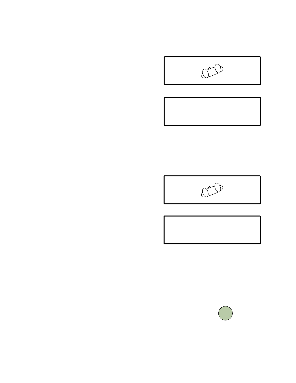
• Stand at the foot of the bed with the padded bottom of footboard against thighs.
• Reach under the mattress from outside edges and find two
knurled knobs, as shown at right.
• Lean into the footboard momentarily to release load on pins while
pulling knobs out toward the side of the bed.
• Rotate the knobs toward the head of the bed to lock pins in
the release position.
• Lower the footboard to a horizontal position.
• Install the foot extension cushion accessory if required.
6. Install extension packs and extension cushions if needed:
FOOTBOARD
Knurled Knob
(on footboard release pin)
7
Page 16

• Adjust the side rails to extended down position.
• Install the extension packs on each side of the seat section.
CAUTION
Ensure that clip at bottom of each extension pack
fully engages side rail shaft.
• Install the extension pack on each side of the seat cushion:
- Press the extension board into the mattress to release the load
on extension board hinge, as shown at right.
- Pivot the extension board hinge downward to a horizontal
position.
Extension
Board
Mattress
1
- Unfold the extension board to a horizontal position.
- Unfold the extension board side to a vertical position.
- Verify the hose is connected securely to each cushion.
- Turn the extension cushion valve (located on patient left side
under side rail) to inflate cushions.
3
4
2
Extension
Board Hinge
7. Raise the side rail to extended up position, unless the decision has been made to not use side rails (see Safety
Information).
8. Verify percussion cushion (if used) is positioned between the
clavicles and the xiphoid process, as shown at right.
Percussion
Cushion
Clavicle
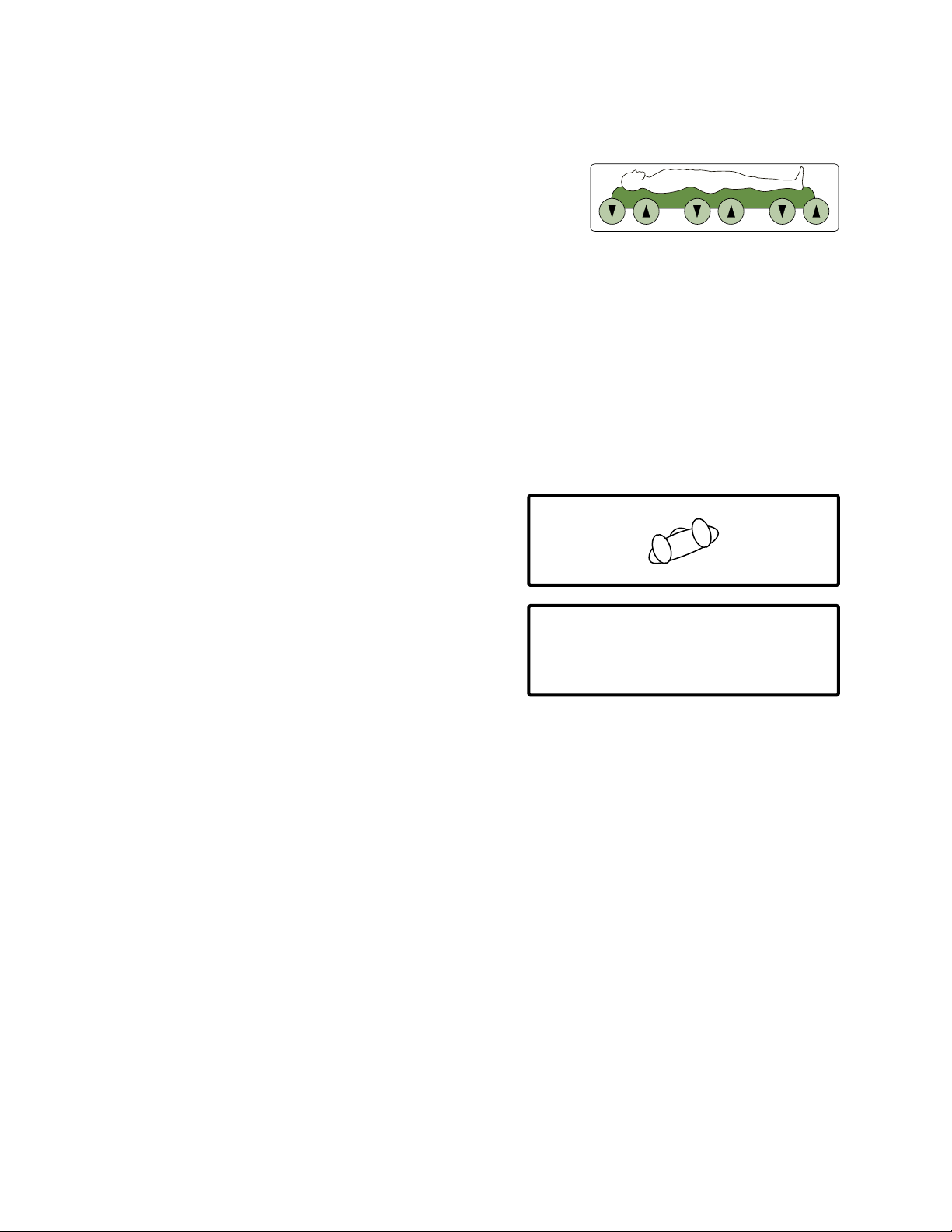
Air Pressure Adjustment
1. With Home menu showing, press the Menu button.
2. Press the Height / Weight button.
3. Press the Increase or Decrease button to adjust patient’s height.
4. Press the Increase or Decrease button to adjust patient’s weight.
5. Press the Enter button to save settings.
6. Allow sufficient time for cushions to respond to air pressure.
7. Perform a hand check beneath shoulders, hips and heels as
shown at right:
• Slide hand under cushion sleeve to rest on
cushion support.
• Lift hand slightly to verify 1.5 to 2 in (35 to 50 mm) of air is
supporting patient.
NOTE: Pulsation should be deactivated when performing hand
check.
8
Xiphoid Process
Cushion Sleeve
Cushion Support
Page 17
8. Manually adjust air pressure as required:
• Press the Air Adjust buttons, shown at right, to adjust air
pressures for head, body and leg cushion sections.
NOTE: Each bar graph that corresponds to the adjusted section of
cushions (head, body, leg) will increase or decrease by one bar
when the corresponding button is pressed twice.
NOTE: Allow sufficient time for cushions to respond to air pressure adjustments before additional changes are
made.
9. Verify air pressure adjustments using hand check.
NOTE: Pulsation should be deactivated when performing hand check.
10. Press the Complete button to return to the Home menu.
Turn Assist Adjustment
AIR ADJUST
1. Press the Menu button on the Home menu.
2. Press the Turn Assist button on the Main menu.
3. Adjust right angle.
4. Adjust right pause time.
5. Adjust center pause time.
6. Zero the Turn Assist hour meter.
7. Press the Left Turn Setting button.
8. Adjust left angle.
9. Adjust left pause time.
<TURN :ON OFF
<PULSE :ON OFF
<PERCUS:ON OFF
LOW RIGHT TURN
RIGHT Angle:
RIGHT Pulse:
CENTER Pause:
Turn Assist Meter:
HOME MENU
TURN ASSIST MENU #1
MEDIUM--------------ADJUST>
0,2,5,10,20,30 min---ADJUST>
0,2,5,10,20,30 min--ADJUST>
INSTAFLATE>
SEAT DEFLATE>
MENU>
STATUS>
XXX.X hours-----ZERO
LEFT TURN SETTING>
10. Press the Exit button to return to the Main menu.
11. Press the Exit button to return to the Home menu.
9
Page 18
Pulsation Adjustment
1. Press the Menu button on the Home menu.
<TURN :ON OFF
<PULSE :ON OFF
<PERCUS:ON OFF
LOW RIGHT TURN
2. Press the Pulsation button on the Main menu.
With the Pulsation menu showing:
• Adjust intensity.
• Adjust cycle time.
• Zero the pulse hour meter.
Current Status:
Intensity:
Cycle Time:
Pulse Hour Meter:
Save Settings
3. Press the Enter button to save settings and return to the Main menu.
4. Press the Exit button to return to the Home menu.
Percussion Adjustment
1. Press the Menu button on the Home menu.
<TURN :ON OFF
<PULSE :ON OFF
<PERCUS:ON OFF
LOW RIGHT TURN
HOME MENU
PULSATION MENU
ON,OFF-----------CHANGE>
LOW MED HI--------ADJUST>
2,5,10,20,40 min--ADJUST>
XXX.X hours-----ZERO>
----------------------ENTER
HOME MENU
INSTAFLATE>
SEAT DEFLATE>
INSTAFLATE>
SEAT DEFLATE>
MENU>
STATUS>
MENU>
STATUS>
2. Press the Percussion button on the Main menu.
With the percussion menu showing:
• Adjust intensity.
• Adjust duration.
Current Status:
Intensity:
Duration:
Frequency:
• Adjust frequency.
• Press the Next Menu button.
• Zero the percussor hour meter.
• Press the Enter button to save settings and return to the Main menu.
• Press the Exit button to return to the Home menu.
Completion of Patient Placement
1. Activate the patient bed exit alarm as required:
• Hold the Scale button on the main control panel until bed movement
stops and the Hold Scale Key to Reposition for Weight message
stops flashing.
PERCUSSION MENU#1
ON,OFF-----------CHANGE>
LOW, MED, HI------ADJUST>
xx min---------------ADJUST>
xx (beat/sec)-------ADJUST>
NEXT MENU>
SCALE
10
Page 19

2. Perform initial patient weighing and save the initial weight in the weight trend chart:
• Press and hold the Scale button on the main control panel until patient weight is not highlighted.
NOTE: For most accurate weight trending, the patient should be weighed in the same position each time. Press
and hold the Scale button to move the bed to the prior weighing position. Patient’s weight will no
longer be highlighted after prior weighing position has been reached. When the Scale button is pressed,
the patient’s weight reading (at patient’s current position) is displayed and highlighted.
• Press the Store Trend button.
• Press the Enter Weight into Weight Chart button.
NOTE: The top line of the weight trend chart will display the date and initial weight. This line is for reference and
will not change. When future weight readings are taken and entered into the weight trend chart, the
most recent reading will appear on the bottom line of the display. This information will move up one line
each time a new weight reading is saved into the weight trend chart and will eventually move up and off
the display.
• Verify patient’s weight has been added to chart.
• Press the Exit button to return to the Scale menu.
• Press the Exit button to return to the Home menu.
3. Verify Turn Assist, pulsation and percussion settings are adjusted as required:
• Press the Status button.
• Review and verify settings.
• Press the Exit button to return to the Home menu.
4. If Turn Assist will be activated, adjust the head and leg sections of bed as required.
5. Activate Turn Assist, pulsation and percussion, as required. With the Home menu showing:
• Press the Turn button to highlight On / Off as required.
• Press the Pulse button to highlight On / Off as required.
• Press the Percussion button to highlight On / Off as required.
6. Observe the patient through a full Turn Assist cycle and adjust as necessary:
• Verify all I.V., drainage tubes and other lines have sufficient slack to accommodate turn and
patient movement.
• Verify air pressure adjustments with hand check beneath shoulders, hips and heels during right pause,
center pause and left pause.
NOTE: Deactivate pulsation during hand check.
• Manually adjust air pressures as required. Allow time for cushions to reach new air pressures and observe
patient through Turn Assist cycle again. Verify air pressures during cycle with hand check after each
adjustment. Perform hand check on both sides of the bed.
NOTE: Deactivate pulsation during hand check.
7. Ensure all brakes are locked.
8. Adjust bed height to lowest height.
11
Page 20

NURSING CARE
It is recommended that all sections of this manual be reviewed prior to product use. Carefully review the
Indications, Contraindications, Risks and Precautions, and Safety Information sections in the Introduction
chapter prior to performing nursing care on the BariAir Therapy System.
Cardiopulmonary Resuscitation (CPR)
1. Press and hold the red CPR button on the main control panel
until the cushions deflate and the bed is level and in lowest
position. The display shown at right will flash until the bed is in
lowest level position.
ALARM
AIR
SCALE
SILENCE
ON/OFF
2. Lower the side rails.
TREND
BED
3. Begin CPR. Use of a crash board is discretionary.
4. After CPR, when patient is clinically stable:
• Raise and lock side rails, unless decision has been made to not use side rails (see Safety Information).
• Press the Press to Cancel CPR button on the main control panel. Pulsation will resume if previously activated.
Turn Assist and percussion will not resume even if previously activated.
• Activate Turn Assist and percussion as required.
AIR ADJUST
FOOT
HEAD
CPR
PATIENT
EXIT
CARDIAC
CHAIR
Auxiliary CPR
If the main control panel is blank and the bed does not respond to the red CPR button:
1. Locate the service switches in base cover on patient right side.
2. Press and hold the CPR rocker switch until cushions deflate.
3. Press bed positioning rocker switches to level and lower bed.
4. Lower the side rails.
5. Begin CPR. Use of a crash board is discretionary.
6. After CPR, when patient is clinically stable:
• Raise and lock the side rails unless decision has been made to
not use side rails (see Safety Information).
• Call ArjoHuntleigh.
L
O
C
K
O
U
T
HI–LO FOOT
LOCK
FOOT HEAD HI–LO HEAD
CPR Switch
PRESS FOR
RAPID
DEFLATE
Service
Switches Box
NOTE:COSMETIC COVER
REMOVED FROM DRAWING FOR
IMPROVED CLARITY
C
P
R
Head of Bed
12
Page 21

Alarms
An audible alarm will sound when:
• Patient has exited bed. Press the Alarm Silence button on the main control panel to silence exit alarm.
• A mechanical obstruction has occurred to hamper bed articulation. This alarm will sound for ten seconds, but
can be canceled by pressing the Cancel button on the main control panel.
• InstaFlate Function or seat deflate functions have been activated.
• Mattress is automatically deflated as bed is positioned for patient exit.
• Battery back-up is activated.
• Turn Assist is activated and one of the following conditions is present:
• Head angle is greater than 40˚.
• Side rail is lowered.
• Extension packs are not in place.
• Leg angle is greater than 15˚.
• Trendelenburg angle is greater than Fowler angle.
• Reverse Trendelenburg angle is greater than 3˚.
Q-Shift Check
1. Verify patient is positioned in center of bed.
2. Verify air pressure settings allow 40% depression into
cushion where patient lies, as shown at right. Perform hand check to
ensure 1.5 to 2 in (35 to 50 mm) of air is supporting patient.
3. If required, ensure Turn Assist is on and patient is being adequately
turned. Turn Assist could be deactivated by one of the following:
• head angle greater than 40˚
• side rail lowered
• Extension packs not in place
• leg angle below 15˚
• Trendelenburg angle is greater than Fowler angle
• Reverse Trendelenburg angle is greater than 3˚
• CPR
• InstaFlate Function or seat deflate function
• right hold, center hold or left hold
• use of scale
4. If required, ensure pulsation is on. Pulsation could be deactivated by one of the following:
• CPR
• InstaFlate Function or seat deflate function
5. If required, ensure percussion is on. Percussion could be deactivated by one of the following:
• CPR
• InstaFlate Function or seat deflate function
• use of scale
Cushion Support
Cushion Sleeve
13
Page 22

Patient Enter / Exit Via Foot of Bed (Ambulatory Patients)
1. Lock brakes on both sides of bed as shown at right (A).
2. Ensure footboard is in locked upright position as shown at right (B). If
installed, remove foot extension cushion accessory.
3. Ensure adjustable corner posts are in appropriate (normal or extended)
position as shown at right (C).
4. Press and hold Patient Exit button on main control panel as shown
at right (D) until footboard stops moving and is almost flat on floor.
Caregiver should always be present during this procedure.
NOTE: Mattress will automatically deflate.
5. Instruct patient to hold on to the stabilization handles located on the
corner posts before entering / exiting the bed as shown at right (E).
6. If patient is entering bed:
• Install extension packs and extension cushions as required as
shown at right (F).
• Press and hold Cardiac Chair button on main control panel as
shown at right (G) to shift patient weight back and ensure against
sliding.
• If required, install foot extension cushion accessory.
(A)
(B)
(C)
(D)
(E)
(F)
(G)
7. Follow all applicable safety procedures and institution protocols
when assisting patient to enter / exit bed.
Patient Transfer to Bed (Non-Ambulatory Patients)
1. Lock brakes on both sides of bed.
2. Level bed.
3. Release footboard and remove head-end corner posts as required.
4. Lower side rails and adjust to narrow door position.
5. Press the InstaFlate button shown in Home menu to create firm surface for patient transfer.
NOTE: Five beeps will sound when the InstaFlate Function is activated and will sound every 20 minutes until the
InstaFlate Function is canceled.
6. Position surfaces side-by-side. Adjust bed height to be even with surface from which patient is
being transferred.
7. Follow all applicable safety procedures and institution protocols when transferring patient.
14
Page 23

8. Position patient in center of mattress.
9. Install extension packs and extension cushions, as required.
10. Raise side rail, unless decision has been made to not use side rails (see Safety Information).
Secure footboard. Replace corner posts.
11. Press Cancel button to deactivate InstaFlate Function and return cushions to previous air
pressure settings.
12. Press and hold Cardiac Chair button on main control panel to shift patient weight back and ensure
against sliding.
13. If required, install foot extension cushion accessory.
Installation of Extension Packs / Cushions
Extension packs and cushions are optional accessories and help to accommodate wider patients by adding 10 in (25 cm) to
the surface width of the bed.
1. Adjust side rails to extended down position.
2. Install extension pack on each side of seat section.
CAUTION
Ensure that clip at bottom of each extension pack
fully engages side rail shaft.
3. Activate extension cushions on each side of head and leg sections,
as shown at right:
• Press extension board into mattress to release load on
extension board hinge.
• Pivot extension board hinge downward to a
horizontal position.
• Unfold extension board to a horizontal position.
• Unfold extension board side to a vertical position.
• Verify hose is connected securely to each cushion
• Turn extension cushion valve (located on patient left side under
side rail) to inflate cushions.
4. Raise side rail to extended up position, unless decision has been
made to not use side rails (see Safety Information).
Extension
Board
Mattress
3
1
2
4
Extension
Board Hinge
5. Reverse above-described procedure to deflate cushions and adjust extension boards to normal / narrow door
position.
15
Page 24

Footboard Release for Taller Patients and Traction
CAUTION
Releasing the footboard may increase risk of injury
by making it easier for the patient to slide out of the bed,
over the footboard and, in some situations, onto the floor.
1. Use full Trendelenburg to shift patient weight back and ensure against sliding.
2. Stand at foot of bed with padded bottom of footboard against thighs.
3. Reach under mattress from outside edges to find two
knurled knobs, as shown at right.
4. Lean into footboard momentarily to release load on pins while
pulling knobs out toward side of bed. Rotate knobs toward
head of bed to lock pins in release position.
5. Lower footboard to horizontal position.
6. Install foot extension cushion accessory if required.
FOOTBOARD
Knurled Knob
(on footboard release pin)
7. Reverse above described procedure to lock footboard in upright position.
WARNING
Patient Migration ‑ As with all specialty bed products that are designed
to reduce shear and pressure on the patient’s skin, the risk of gradual
movement and / or sinking into hazardous positions of entrapment and
/ or inadvertent bed exit may be increased. While the BariAir Therapy
System footboard can gradually release under loads, patients may slide
out of bed over the footboard, potentially risking serious injury to the
patient. Such risks are increased if the head of the bed is elevated or if the
footboard has been manually released.
Bed Adjustment to Cardiac Chair Position
1. Ensure footboard is locked in upright position.
2. Press and hold Cardiac Chair button on main control panel.
CARDIAC
CHAIR
16
Page 25

Patient Transport in Cardiac Chair Position
1. Position patient in cardiac chair position.
2. Engage scale lock-down clamp (located at head of bed in center of caster frame).
3. Unlock brakes. Align casters to direction of travel.
4. Unplug power cord from wall outlet. Store cord by
wrapping it around power cord hangers on base cover. The
display shown at right will appear and flash.
• An approximate percentage of reserve power remaining
Shut OFF Battery Backup---------CANCEL >
will count down in display.
• A low beep will sound when the bed is unplugged and will sound again every minute until battery back-up
is canceled.
• A fully charged bed will provide static air support for approximately 60 minutes (one hour). Use of bed
functions (head up / down, foot up / down, bed up / down, etc.) will decrease reserve power more rapidly
than static air support.
• Turn Assist, pulsation, percussion and the exit alarm will be deactivated. Static air support will not be
deactivated during the battery back-up.
5. Adjust cushions and packs to normal / narrow door position:
• Turn extension cushion valve (located on patient left side under side rail) to stop air flow to cushions.
• Use hands or extension board to force air from cushion.
NOTE: Cushion will deflate more rapidly if hose is disconnected.
• Press deflated extension cushion into side of mattress and fold extension board to normal / narrow door
position.
• Lift and remove extension packs from each side of seat section.
Battery Back Up !
Reserve Power: XXX %
6. Set adjustable corner posts to normal position:
• Step on adjustable corner post pedal to unlock post.
• Push adjustable corner post toward foot of bed until post locks into position near footboard.
7. Rotate main control panel to align with side rail.
8. Follow all safety procedures and institution protocols when transporting patient in cardiac chair position.
NOTE: The bed will shut off automatically to conserve battery power if the bed is unplugged for an hour with air off
and the display on. To restart the bed, plug the power cord into a wall outlet.
NOTE: Plug power cord into a wall outlet immediately
if the display shown at right appears and flashes. Less
than ten minutes of reserve power is left. It will take
approximately four hours to recharge the battery fully.
Shut OFF Battery Backup---------CANCEL >
Battery Back Up !
Reserve Power: XXX %
A protection circuit helps protect the battery from
overcharging.
17
Page 26

9. Plug power cord into a wall outlet when destination is reached.
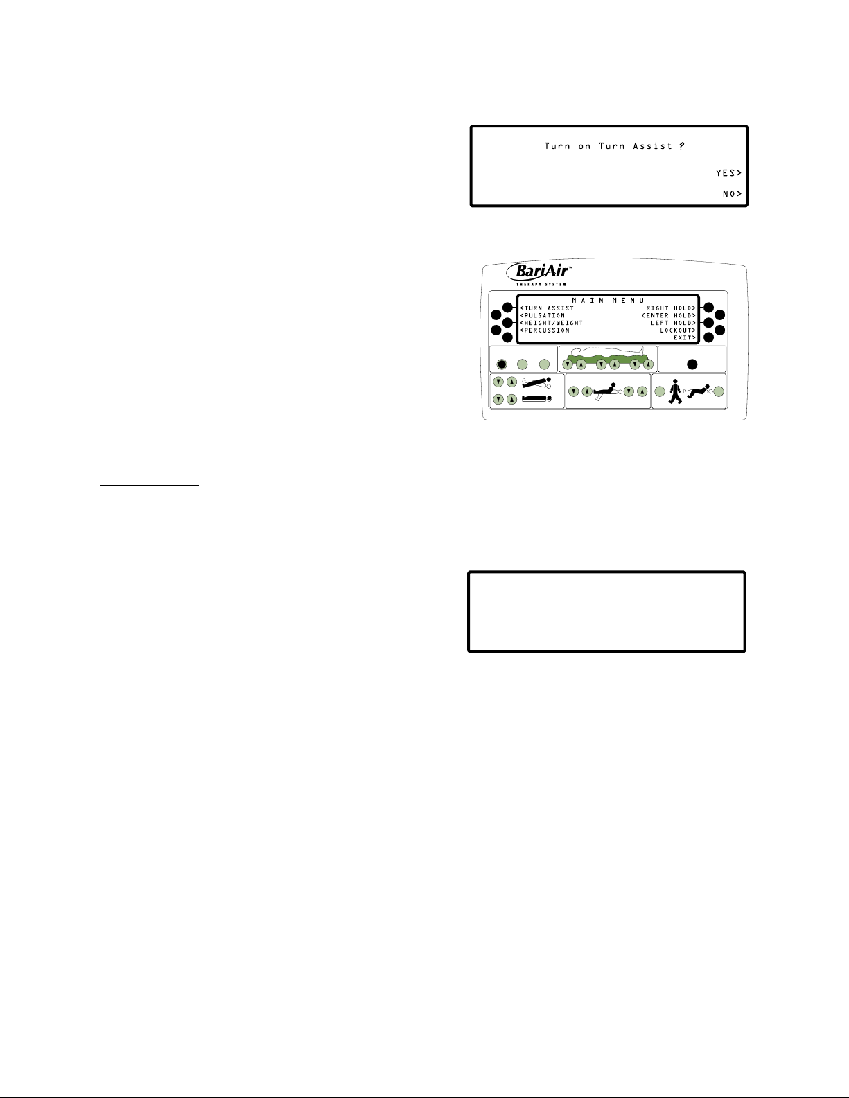
NOTE: If Turn Assist was on before bed was unplugged, five beeps will sound and the Turn On Turn Assist? menu will
appear to prompt the caregiver to reactivate Turn Assist. Pulsation will be restored if it was activated before bed
was unplugged. If percussion and exit alarm were on before the bed was unplugged, they will be deactivated.
Reactivate percussion from the Home menu. Reactivate exit alarm from the Scale menu.
Side Rail Operations
CAUTION
WARNING: Use of restraints, including side rails, can be critical to
patient safety. Serious injury or death can result from the use (potential
entrapment) or non‑use (potential patient falls) of side rails or other
restraints. See related Safety Information.
Side Rail Positions
• normal up / down position (43.25 in wide [110 cm] rail-to-rail)
• extended up / down position (53.25 in wide [135 cm] rail-to-rail)
• narrow door position (40.25 in wide [102 cm] rail-to-rail)
Adjust Side Rail to Narrow Door Position
• Grasp lower bar located in center of side rail,
as shown at right.
Rotate side rail until top of
rail is 3 in (7.5 cm) above seat
board.
• Rotate side rail until top of rail is 3 in (7.5 cm) above
seat board.
• Push rail inward until it contacts bed frame.
CAUTION
After narrow door passage, raise side rails to full up position.
Side Rail Operating Tips
• Side rails slide easiest when operator pushes or pulls lower bar in center of side rail.
• Side rails must be in down position when being adjusted to normal or extended, and full up for narrow door
position.
18
Page 27

Extension Cushion Operations
Extension Board Positions
• normal / narrow door position
• extended position
Adjust Extension Packs and Cushions to Normal Position
1. Turn extension cushion valve (located on patient left side under side rail) to stop air flow to cushions.
2. Use hands or extension board to force air from cushion.
NOTE: Cushion will deflate more rapidly if hose is disconnected.
3. Press deflated extension cushion into side of mattress and fold extension board to normal / narrow
door position.
4. Lift and remove extension pack from each side of seat section.
Adjustable Corner Post Operations
Adjustable Corner Post Positions
• Normal position (40.25 in [102 cm] wide post-to-post)
• Extended position (59.75 in [152 cm] wide post-to-post)
Set Adjustable Corner Post to Normal Position
1. Step on adjustable corner post pedal to unlock post.
2. Push adjustable corner post toward foot of bed until post locks into position near footboard.
Skin Care
1. Remove excess moisture and keep skin dry and clean.
2. Maintain proper air pressures in accordance with the Air Pressure Adjustment section in the Patient
Placement chapter of this manual.
3. Check skin regularly, particularly in areas where incontinence and drainage occur.
Incontinence / Drainage
1. Use breathable underpads.
NOTE: Breathable Dri-Flo™ Pads are recommended for incontinent patients. Do not use plastic-backed underpads.
Plastic tends to block moisture vapor transmission and air flow from mattress. Breathable Dri-Flo Pads are
absorbent and permit more air flow.
2. Watch for incontinence or drainage and provide appropriate skin care following each episode.
19
Page 28

Patient Bathing
1. Adjust bed height and level bed for ease of bathing.
2. Press InstaFlate button to create firm surface.
NOTE: Five beeps will sound when the InstaFlate Function is activated and will sound every 20 minutes until the
InstaFlate Function is canceled.
3. Lower side rail on caregiver’s side. Never leave patient unattended when side rails are lowered, unless the
decision has been made to not use the side rails.
4. Bathe patient following institution protocols. Wipe cover sheet while bathing patient.
NOTE: Avoid spilling fluids on any part of the main control panel or hand controls. Fluids remaining on the controls can
cause corrosion, which may cause the components to fail, or operate erratically, possibly producing potential
hazards to patient and staff.
5. Dry cover sheet with towel. Remaining moisture will evaporate rapidly with air flow.
6. Raise and lock side rails, unless decision has been made to not use side rails (see Safety Information).
7. Press Cancel button to deactivate the InstaFlate Function. Cushions will return to previous air
pressure settings.
8. Reactivate Turn Assist and percussion as needed. Pulsation will be restored automatically.
9. Adjust bed height to lowest position.
10. Press and hold Cardiac Chair button on main control panel to shift patient weight back and ensure against sliding.
Bedpan Placement
1. Adjust bed height and level bed for ease of bedpan placement.
2. Press Seat Deflate button on main control panel to reduce air pressures in cushions of body section by 50%.
NOTE: Five beeps will sound when seat deflate is activated.
3. Lower side rail on caregiver’s side. Never leave patient unattended when side rails are lowered, unless the
decision has been made to not use side rails.
4. Position bedpan parallel to patient’s buttocks. Roll patient toward opposite side rail.
5. Push bedpan down into cushions and position bedpan underneath patient.
6. Roll patient onto bedpan, keeping one hand on bedpan.
7. Raise and lock side rail, unless decision has been made to not use side rails (see Safety Information).
8. Adjust head and foot of bed for patient comfort.
20
Page 29

Bedpan Removal
1. Adjust bed height and level bed for ease of bedpan removal.
2. Lower side rail on caregiver’s side.
3. Grasp bedpan firmly with one hand. Roll patient toward opposite side rail.
4. Cleanse patient’s posterior.
5. Remove bedpan and finish cleaning patient.
6. Return patient to supine position in center of mattress.
7. Raise and lock side rail, unless decision has been made to not use side rails (see Safety Information).
8. Press Cancel button to deactivate seat deflate and return cushions to previous air pressure settings.
9. Reactivate Turn Assist and percussion, as needed. Pulsation will be restored automatically.
10. Adjust bed height to lowest position.
11. Press and hold Cardiac Chair button on main control panel to shift patient weight back and ensure against
sliding.
Patient Positioning
The following bed and air functions have been built into the BariAir Therapy System to accommodate numerous clinical
positioning requirements. All functions are activated from the main control panel. Head, foot, bed and Trendelenburg
positioning are also activated from the hand control.
Right Hold
Use right hold to turn patient to target right turn angle and hold bed position.
• To activate right hold, press Right Hold button in Main
menu display, shown at right.
NOTE: Turn Assist will be deactivated. If activated, pulsation
and percussion will continue.
<TURN ASSIST
<PULSATION
<HEIGHT/WEIGHT
<PERCUSSION
Center Hold
Use center hold to turn patient to a level position and hold bed position.
• To activate center hold, press Center Hold button in
Main menu display, shown at right.
NOTE: Turn Assist will be deactivated. If activated, pulsation
and percussion will continue.
<TURN ASSIST
<PULSATION
<HEIGHT/WEIGHT
<PERCUSSION
RIGHT HOLD>
CENTER HOLD>
LEFT HOLD>
LOCKOUT>
EXIT>
RIGHT HOLD>
CENTER HOLD>
LEFT HOLD>
LOCKOUT>
EXIT>
21
Page 30

Left Hold
Use left hold to turn patient to target left turn angle and hold bed position.
• To activate left hold, press Left Hold button in Main menu
display, shown at right.
NOTE: Turn Assist will be deactivated. If activated, pulsation
and percussion will continue.
<TURN ASSIST
<PULSATION
<HEIGHT/WEIGHT
<PERCUSSION
RIGHT HOLD>
CENTER HOLD>
LEFT HOLD>
LOCKOUT>
EXIT>
Trendelenburg / Reverse Trendelenburg
Use Trendelenburg / Reverse Trendelenburg to adjust patient support surface from approximately
14˚ Trendelenburg to 14˚ Reverse Trendelenburg.
• To adjust bed position, use Trend buttons on main
control panel, shown at right:
• Press down button for Trendelenburg.
• Press up button for Reverse Trendelenburg.
TREND
Cardiac Chair
Use Cardiac Chair button to position patient automatically to 25˚ head articulation, 30˚ knee articulation and
14˚ Trendelenburg.
1. Ensure footboard is locked in upright position.
2. Press and hold Cardiac Chair button, shown at right, on main control panel. Release
button at any time to stop automatic bed movement and positioning.
CARDIAC
CHAIR
General Operation
Avoid contact of sharp instruments with cover sheet and cushions. Punctures, cuts
and tears may prevent proper inflation.
22
Page 31

CARE AND CLEANING
The following are the ArjoHuntleigh recommended daily and weekly cleaning and infection control procedures for
the BariAir Therapy System while it is in use. If the product is to be purchased or utilized for long-term rentals, it is
recommended that ArjoHuntleigh be contacted for recommended infection control procedures to be used by the
facility or home user.
It is recommended that all sections of this manual be reviewed prior to product use. Carefully review the
Indications, Contraindications, Risks and Precautions and Safety Information sections in the Introduction
chapter prior to cleaning the BariAir Therapy System.
Daily Care and Cleaning of the BariAir Therapy System While In Use
NOTE: The patient need not be removed from the bed when performing daily cleaning procedures.
The patient may be bathed as the patient support surface is being cleaned.
1. Adjust bed height and level bed for ease of bathing.
2. Press InstaFlate button to create a firm surface.
NOTE: Five beeps will sound when the InstaFlate Function is activated.
3. Lower side rail on caregiver’s side. Never leave patient unattended when side rails are lowered, unless the
decision has been made to not use the side rails.
4. Bathe patient following institution protocols. Wipe cover sheet while bathing patient.
NOTE: Avoid spilling fluids on any part of the main control panel or hand controls. Fluids remaining on the controls
can cause corrosion, which may cause the components to fail, or operate erratically, possibly producing
potential hazards to patient and staff.
5. Move cover sheet for access and wipe soiled cushions, as needed.
NOTE: Replace and launder extensively soiled cover sheet or cushions.
6. Dry cover sheet with towel. Remaining moisture will evaporate rapidly with air flow.
7. Raise and lock side rails, unless decision has been made to not use side rails (see Safety Information).
8. Press Cancel button to deactivate the InstaFlate Function. Cushions will return to previous air
pressure settings.
9. Reactivate Turn Assist and percussion as needed. Pulsation will be restored automatically.
10. Adjust bed for patient comfort.
11. Press and hold the Cardiac Chair button on the main control panel to shift patient weight back and ensure
against sliding.
23
Page 32

Weekly Care and Cleaning of the BariAir Therapy System While In Use
The BariAir Cover Sheet should be replaced weekly or more often as needed. Excessively soiled mattress components
should be replaced and laundered. Contact your ArjoHuntleigh representative for infection control procedures.
Preventive Maintenance
• Monthly Cleaning ‑ The cushions should be laundered at least monthly.
• Air Filter ‑ Clean / change air filter(s) when necessary.
• Battery Inspection ‑ Inspect batteries and replace in pairs. If batteries are more than 28 months old from the
date of manufacture, dispose of batteries according to local and state regulations. Install a battery history label on
the BariAir Therapy System battery cover with the recorded date when the batteries should next be replaced. Apply
label in a visible location so that all information is displayed.
NOTE: It is recommended that all preventative and battery maintenance procedures be performed only by qualified
ArjoHuntleigh service personnel or ArjoHuntleigh-approved personnel.
NOTE: When not in service, bed must remain plugged in to maintain battery charge.
OPERATING INSTRUCTIONS
This chapter contains instructions for setting and adjusting functions of the BariAir Therapy System. It is
recommended that all sections of this manual be reviewed prior to product use. Carefully review the Indications,
Contraindications, Risks and Precautions, and Safety Information sections in the Introduction chapter prior
to operating on the BariAir Therapy System.
Power-Up Procedure
1. Plug power cord into properly grounded wall outlet.
Ensure power to this outlet is not controlled by a wall switch.
After approximately ten seconds, the display shown at right
will appear on the main control panel.
• After approximately 25 seconds, the display shown at
right will appear.
2. Press Air On / Off button, shown at right, on main control panel.
• The display shown at right will appear temporarily
and then change to the Home menu.
• Pulsation will resume automatically if activated prior to air
being deactivated.
Air Switched Off !
Press ON/OFF Button to Start
AIR
ON / OFF
Air Switched On !
Welcome to KCI’s BariAir
Therapy System
24
Page 33

Main Control Panel
AIR
ON/OFF
ALARM
SILENCE
SCALE
TREND
BED
FOOT HEAD
PATIENT
EXIT
CARDIAC
CHAIR
AIR ADJUST
CPR
The main control panel is located on an adjustable corner post at the foot of the bed.
SCALE
Press to view patient’s
current weight. Press
and hold to move
AIR ADJUST
Press to view and
adjust air pressures
in mattress.
bed to position of
prior weighing for
most accurate weight
trending.
CPR
Press and hold until
cushions deflate and
bed is level and in
ALARM SILENCE
lowest position.
Press to silence patient
bed exit alarm.
AMBULATORY
PATIENT BED EXIT
AIR ON / OFF
Press to turn air on
and off.
Press and hold to move
bed into position to
allow patient to exit at
foot of bed.
BED POSITIONING
BUTTONS
Trend / Rev Trend
Bed Up / Down
Foot Up / Down
CARDIAC CHAIR
Press and hold to move
bed into Cardiac Chair
position.
Head Up / Down
Use the main control panel to:
• Activate / deactivate the air supply to cushions and bladders on the bed.
• View, set and adjust air functions and therapies (Turn Assist, pulsation, percussion, InstaFlate Function, seat
deflate and air pressures).
• View a bar graph of and manually adjust air pressures in each section of cushions (head, body and foot).
• Activate and silence the bed exit alarm.
• View, set and adjust scale readings (zero, preset, alarm On / Off, weight hold / new weight position, delay, store
trend and show chart, exit).
• Set and adjust air function lock-outs (Turn Assist, pulsation, percussion and air pressures).
• Activate CPR.
• Position the bed (head up / down, foot up / down, bed up / down, etc.).
• Assist the patient to enter and exit the bed.
Home Menu
Use the Home menu shown at right to:
• Activate / deactivate Turn Assist, pulsation therapy and
percussion therapy.
• View the current patient angle and direction of turn.
<TURN :ON OFF
<PULSE :ON OFF
<PERCUS:ON OFF
LOW RIGHT TURN
HOME MENU
INSTAFLATE>
SEAT DEFLATE>
MENU>
STATUS>
• Activate / deactivate the InstaFlate Function and seat deflate.
• Access the Main menu and the Status menu.
1. With Home menu showing, press Turn button to activate / deactivate Turn Assist. The selection will
be highlighted.
2. With Home menu showing, press Pulse button to activate / deactivate pulsation. The selection will
be highlighted.
25
Page 34

3. With Home menu showing, press Percus button to activate / deactivate percussion. The selection will
be highlighted.
InstaFlate Function
Use the InstaFlate Function to assist in patient transfer and bathing by increasing air pressures in all cushions to create a
firm surface.
1. With Home menu showing, press InstaFlate button.
The display shown at right will appear and flash.
• Turn Assist, pulsation and percussion will be deactivated.
• Five beeps will sound when the InstaFlate Function is
activated and will sound again every 20 minutes until
the InstaFlate Function is canceled.
2. Press Cancel button. The display shown at right will appear
temporarily and then return to the Home menu.
NOTE: If Turn Assist was on before the InstaFlate Function
was activated, five beeps will sound and the display
shown at right will appear to prompt the caregiver
to reactivate Turn Assist. If pulsation was activated
before the InstaFlate Function was activated, it will be
restored. Percussion will not be restored.
Seat Deflate
Use seat deflate to assist in bedpan placement by reducing the air pressures in the cushions of the body section by 50%.
1. With Home menu showing, press Seat Deflate button.
The display shown at right will appear and flash.
• Turn Assist, pulsation and percussion will
be deactivated.
• Five beeps will sound when seat deflate is activated and
will sound continuously until seat deflate
is canceled.
2. Press Cancel button. The display shown at right will appear
temporarily and then return to the Home menu.
26
Page 35
NOTE: If Turn Assist was on before seat deflate was
activated, five beeps will sound and the display shown at
right will appear to prompt the caregiver to reactivate Turn
Assist. If pulsation was on before seat deflate was activated,
it will be restored. Percussion will not be restored.
Main Menu
Use the Main menu shown at right to access Turn Assist,
Pulsation, Height / Weight preset and Percussion menus.
Use the Main menu to turn the patient to the right / left Turn
Assist angle and to hold the patient at that angle. The patient
can also be brought to and held in a level (center) position.
The Lock-Out menu is also accessed through the Main menu.
• With Home menu showing, press Menu button. The Main menu
will appear.
ON/OFF
AIR
TREND
BED
ALARM
SILENCE SCALE
AIR ADJUST
FOOT
HEAD
PATIENT
CPR
CARDIAC
EXIT
CHAIR
NOTE: If a change is not made within approximately one minute,
the display will return automatically to the Home menu.
Turn Assist Menus
Use the Turn Assist menus to view and adjust current status, right and left turn angles and right, left and center pause times.
Use the Turn Assist menus to view the number of hours of turning the patient has received and to zero the Turn Assist hour
meter.
1. With Main menu showing, press Turn Assist button.
Turn Assist menu #1 will appear, as shown at right.
NOTE: Right and center pause times for Turn Assist
are highlighted.
RIGHT Angle:
RIGHT Pulse:
CENTER Pause:
Turn Assist Meter:
TURN ASSIST MENU #1
MEDIUM--------------ADJUST>
0,2,5,10,20,30 min---ADJUST>
0,2,5,10,20,30 min--ADJUST>
XXX.X hours-----ZERO
LEFT TURN SETTING>
NOTE: If a change is not made within approximately
one minute the display will return automatically to
the Home menu. All settings shown at the time will be
saved automatically and become the current settings.
2. Press Right Angle-Adjust button to sequentially display 0, LOW, MEDIUM or HIGH.
Right angle is the target right turn angle to which the patient will turn during Turn Assist and during right hold.
NOTE: If a right angle of 0 is selected, 0 cannot be selected for the left angle.
3. Press Right Pause-Adjust button to select and highlight 0, 2, 5, 10, 20 or 30 minutes.
Right pause is the amount of time the patient is held in place once the target right turn angle is reached.
4. Press Center Pause-Adjust button to select and highlight 0, 2, 5, 10, 20 or 30 minutes.
Center pause is the amount of time the patient is held in a level position after turning to the right or left.
27
Page 36

5. If appropriate, press Zero button to calibrate the
Turn Assist hour meter. The display shown at right
will appear.
The Turn Assist hour meter indicates the number of hours of
turning a patient has received.
• Press Yes button to calibrate the meter to 0 hours and
return to Turn Assist menu #1.
• Press No button to return to Turn Assist menu #1.
6. Press Left Turn Setting button. Turn Assist menu #2 will
appear, as shown at right.
7. Press Left Angle-Adjust button to sequentially
display 0, LOW, MEDIUM or HIGH.
Left angle is the target left turn angle to which the patient will turn during Turn Assist and during left hold.
NOTE: If a left angle of 0˚ is selected, 0 cannot be selected for the right angle.
8. Press Left Pause-Adjust button to select and highlight 0, 2, 5, 10, 20 or 30 minutes.
Left pause is the amount of time the patient is held in place once the target left turn angle is reached.
9. Press Change button to activate / deactivate Turn Assist by selecting and highlighting either on or off.
Current status indicates if Turn Assist is activated or deactivated.
10. Press Exit button to save Turn Assist settings and return to the Main menu.
Pulsation Menu
Use the Pulsation menu to view and adjust current status, intensity, cycle time, to view the number of hours of pulsation
therapy and to zero the pulse hour meter.
1. With Main menu showing, press Pulsation button. The
Pulsation menu will appear, as shown at right.
NOTE: Pulsation will be activated automatically
if activated prior to air being deactivated.
If pulsation has been deactivated, it will be reactivated
when Pulsation button is pressed.
NOTE: The current status, intensity, and cycle time for pulsation are highlighted.
NOTE: If a change is not made within approximately one minute the display will return automatically to the Home
menu. All settings shown at the time will be saved automatically and become the current settings.
2. Press Change button to activate / deactivate pulsation by selecting and highlighting either on or off.
Current status indicates if pulsation therapy is activated or deactivated.
3. Press Intensity-Adjust button to select and highlight LOW, MEDIUM or HIGH.
Intensity determines how high above and how low below the target pressure (or mid-position) cushions will
inflate / deflate during pulsation.
28
Page 37

4. Press Cycle Time-Adjust button to select and highlight 2, 5, 10, 20 or 40 minutes.
Cycle Time determines how quickly a cushion will complete a full cycle (i.e., inflate, return to mid-position,
deflate, return to mid-position) and be ready to inflate again.
5. If appropriate, press Zero button to reset the pulse hour
meter. The display shown at right will appear.
The pulse hour meter indicates the number of hours of
pulsation therapy a patient has received.
• Press Yes button to reset the meter to 0 hours and return
to the Pulsation menu.
• Press No button to return to the Pulsation menu.
6. Press Enter button to save Pulsation menu settings and then return to the Main menu.
Height / Weight Preset
Use the Height / Weight Preset menu to set air pressures in each section of cushions to target pressures based on the patient’s
height and weight. Height values can be adjusted from 4 ft 0 in (122 cm) to 6 ft 6 in (198 cm) in one inch increments. Weight
values can be adjusted from 250 lb (113 kg) to 850 lb (386 kg) in 10 lb (4.5 kg) increments.
1. With Main menu showing, press Height / Weight button.
The Height / Weight Preset menu will appear, as shown at
right.
NOTE: If a change is not made within approximately one
minute, the display will return automatically to the
Home menu. All settings shown at the time will be
saved automatically and become the current settings.
2. To adjust height values:
• Press Height-Increase button to increase height value in 1 in (2.54 cm) increments.
• Press Height-Decrease button to decrease height value in 1 in (2.54 cm) increments.
3. To adjust weight values:
• Press Weight-Increase button to increase weight value 10 lb (4.5 kg) initially; after which, if button is pressed
and held, weight increases in 20 lb (9.0 kg) increments.
• Press Weight-Decrease button to decrease weight value in 10 lb (4.5 kg) increments initially; after which, if
button is pressed and held, weight decreases in 20 lb (9.0 kg) increments.
4. Press Enter button. The display shown at right will
appear. Perform a hand check to ensure air pressures are
properly adjusted for individual patient. Press Complete
button to save adjusted height and weight values and then
return to the Home menu.
NOTE: The target air pressures based on the height / weight preset will be overridden if the target air pressures are
adjusted manually by pressing the air adjust buttons on the main control panel.
29
Page 38

NOTE: To override the manually adjusted target air pressures with the target pressures based on height / weight
preset, one of the height / weight preset values must be adjusted, then adjusted back and then saved.
Percussion Menus
Use the Percussion menus to view and adjust current status, intensity, duration, frequency, to view the number of hours of
percussion therapy the patient has received and to zero the percussion hour meter.
1. With Main menu showing, press Percussion
button.
The Percussion menu #1 will appear, as shown at right.
NOTE: The current status and intensity for percussion
are highlighted.
NOTE: If a change is not made within approximately
one minute the display will return automatically
to the home menu. All settings shown at the time
will be saved automatically and become the current settings.
2. Press Change button to activate / deactivate percussion by selecting and highlighting either on or off.
Current status indicates if percussion therapy is activated or deactivated.
3. Press Intensity-Adjust button to select and highlight LOW, MEDIUM or HIGH.
Intensity is the range of pressure exerted on the lung area during percussion therapy to aid in the mobilization of
fluids and mucous.
4. Press Duration-Adjust button to sequentially display 5 through 90 minutes, in five minute increments.
Duration is the length of time percussion therapy will be provided.
5. Press Frequency-Adjust button to sequentially display 1 through 19 beats / second, in one beat
/ second increments.
Frequency is the number of beats per second that percussion therapy will provide.
6. Press Next Menu button. Percussion menu #2 will appear,
as shown at right.
7. If appropriate, press Zero button to reset the percussion
hour meter. The display shown at right will appear.
The percussion hour meter indicates the number of
hours of percussion therapy a patient has received.
• Press Yes button to reset the meter to 0 hours and
return to Percussion menu #2.
• Press No button to return to Percussion menu #2.
8. Press Enter button to save Percussion menu settings and then return to the Main menu.
30
Page 39

Right Hold
Use right hold to turn the patient to the target right turn angle and hold bed position.
1. With Main menu showing, press Right Hold button.
RIGHT TURN
The right turn display shown at right will appear.
• The patient’s current position will be graphically
displayed and will change to reflect the patient’s
LOW RIGHT TURN
changing position.
NOTE: Allow a few moments for the air pressures in
the turning bladders to adjust before a change will be seen on the display.
• Turn Assist will be deactivated. Pulsation and percussion will continue if activated.
2. Press Exit button to deactivate right hold and then return to the Home menu.
NOTE: If Turn Assist was on before right hold was activated, it will not be restored automatically. Reactivate Turn
Assist from the Home menu.
Center Hold
Use center hold to turn the patient to a level position and hold bed position.
1. With Main menu showing, press Center Hold button.
The centering display shown at right will appear.
• The patient’s current position will be graphically
displayed and will change to reflect the patient’s
changing position.
NOTE: Allow a few moments for the air pressures in the
turning bladders to adjust before a change will be seen on the display.
• Turn Assist will be deactivated. Pulsation and percussion will continue if activated.
RIGHT>
CENTER>
LEFT>
EXIT>
2. Press Exit button to deactivate center hold and then return to the Home menu.
NOTE: If Turn Assist was on before center hold was activated, it will not be restored automatically. Reactivate Turn
Assist from the Home menu.
Left Hold
Use left hold to turn the patient to the target left turn angle and hold bed position.
1. With Main menu showing, press Left Hold button.
The left turn display shown at right will appear.
• The patient’s current position will be graphically
displayed and will change to reflect the patient’s
changing position.
NOTE: Allow a few moments for the air pressures in
the turning bladders to adjust before a change will be seen on the display.
• Turn Assist will be deactivated. Pulsation and percussion will continue if activated.
31
Page 40

2. Press Exit button to deactivate left hold and then return to the Home menu.
NOTE: If Turn Assist was on before left hold was activated, it will not be restored automatically. Reactivate Turn Assist
from the Home menu.
Lock-Out Menu
Use the Lock-Out menu to:
• Selectively disable air functions to prevent their activation
(locked-off ).
• Selectively allow air functions to be adjusted (unlock).
Lock-Out Switch
L
O
C
K
O
U
LOCK
T
HI–LO FOOT
FOOT HEAD HI–LO HEAD
PRESS FOR
RAPID
DEFLATE
C
P
R
• Selectively freeze air function settings to prevent their
adjustment (freeze).
NOTE: Refer to the air function lock-out chart at the end of this
section for additional information.
NOTE: Lock-outs for bed positioning controls on the main control
panel and hand control are set by pressing the lock-out
switch, shown at right, located in the head-end of the base
cover on the patient right side.
Service
Switches Box
NOTE:COSMETIC COVER
REMOVED FROM DRAWING FOR
IMPROVED CLARITY
Head of Bed
1. With Main menu showing, press Lock-Out button. Lock-Out
menu #1 shown at right will appear.
2. Press Change buttons to sequentially display
UNLOCK, FREEZE and LOCKED OFF settings for
Turn Assist, pulsation, air pressure adjustment
and percussion.
3. Press Enter button to save lock-out settings and then return to the Home menu.
NOTE: After lock-outs are set, a beep will sound if a
button is pressed to activate or adjust an air
function that has been locked off or frozen.
The display shown at right will appear
temporarily and then return to the Home menu.
32
Page 41

The following chart defines each air function lock-out and which air functions it will affect.
AIR FUNCTION LOCK-OUT CHART
AIR FUNCTION LOCKED-OFF UNLOCK FREEZE
Turn Assist
(Power Up Default: Off)
Turn Assist is disabled. A
beep will sound if button
is pressed.
PULSATION
(Power Up Default: On)
AIR ADJUST
(Power Up Default: Off)
PERCUSSION
(Power Up Default: OFF)
Pulsation cannot be
locked off.
Air flow into the cushions
cannot be locked off.
Percussion is disabled. A
beep will sound if button
is pressed.
Status Menu
Use the Status menu shown at right to view:
• Turn Assist current status, right turn angle and pause time
and left turn angle and pause time.
• Pulsation current status, intensity and cycle time.
• Percussion current status, intensity and frequency.
Allows normal operation
and adjustment of
Turn Assist.
Allows normal operation
and adjustment of
pulsation.
Allows normal adjustment
of air pressures using the
Air Adjust buttons on the
main control panel or
Height / Weight menu.
Allows normal operation
and adjustment of
percussion.
AIR
ALARM
ON/OFF
SILENCE SCALE
TREND
BED
FOOT
Can activate / deactivate
Turn Assist, but settings
cannot be adjusted.
Can activate / deactivate
pulsation, but settings
cannot be adjusted.
The Air Adjust buttons on
the main control panel or
Height / Weight menu
cannot manually adjust
the current air pressure
settings.
Can activate / deactivate
percussion, but settings
cannot be adjusted.
AIR ADJUST
HEAD
PATIENT
CPR
CARDIAC
EXIT
CHAIR
1. With Home menu showing, press Status button. The Status menu will appear.
NOTE: The Status menu is for viewing only. If the Exit button is not pressed within approximately one minute, the
display will return automatically to the Home menu.
2. Press Exit button and then return to the Home menu.
33
Page 42

Air Pressures Display
Use the bar graph display shown at right to view and manually
adjust pressures for each of the three sections of cushions: head, body
and leg. The bar graph display is accessed by pressing any Air Adjust
button.
ON/OFF
AIR
ALARM
SILENCE SCALE
AIR ADJUST
CPR
The following information is represented on each bar graph,
as shown at right:
• The dotted bar indicates height / weight preset target pressure
for that section of cushions.
• The solid bars indicate the target pressure in that set of cushions.
TREND
BED
Target air
pressure
FOOT
HEAD
PATIENT
EXIT
CARDIAC
CHAIR
Height / Weight
preset target
pressure
Actual air
pressure
Solid bars are manually adjusted by pressing the Air Adjust
buttons.
• The manually adjusted pressure (solid bars) will override the height / weight preset pressure (dotted bar).
• The arrows on each side of a bar graph indicate actual air pressures in that section of cushions. With pulsation
therapy activated, every other cushion inflates as the cushions in between deflate, so the arrows rise and fall as
the cushions they represent inflate and deflate.
• Press Air Adjust up buttons shown at right to manually
increase air pressures to that section of cushions.
AIR ADJUST
• Press Air Adjust down buttons shown at right to manually
decrease air pressures to that section of cushions.
• Press Exit button to save manually adjusted settings and
return to the Home menu.
NOTE: The target air pressures based on the height / weight preset will be overridden if the target air pressures are
adjusted manually by pressing Air Adjust buttons on the main control panel.
NOTE: To override the manually adjusted target air pressures with the target pressures based on height / weight
preset, one of the height / weight preset values must be adjusted, then adjusted back and then saved.
Alarm Silence
Use the Alarm Silence button on the main control panel to silence the bed exit alarm.
• Press Alarm Silence button shown at right to silence bed exit alarm.
34
ALARM
SILENCE
Page 43

Scale Menu
Use the Scale menu shown at right to access various scale
functions as described in the following sections:
• Zero • Delay
• Preset • Store Trend
• Alarm • Weight Trend Chart
<ZERO DELAY>
<PRESET STORE TREND>
<ALARM: ON OFF SHOW CHART>
<Weight Hold/New Weight POSN EXIT>
AIR
ALARM
ON/OFF
SILENCE SCALE
S C A L E M E N U
PATIENT WEIGHT: XX.X Lb/ X.X Kg
AIR ADJUST
• Weight Hold • Auxiliary CPR
TREND
BED
FOOT
HEAD
PATIENT
EXIT
1. Press and hold the Scale button to move the bed into a preset
weighing position.
2. Continue to hold the Scale button until the bed stops moving and the patient weight is no
longer highlighted.
SCALE
3. Release the Scale button, shown at right, to display patient weight.
NOTE: For most accurate weight trending, the bed should be in the same
position each time the patient is weighed.
NOTE: If a new weighing position is desired, press the Weight Hold / New Weight Position button. Move the bed to
the desired weighing position and then press the Set Weight Hold / New Weight Position button. This will reset
the weighing position to the current bed position.
NOTE: Turn Assist, pulsation and percussion will be deactivated when the Scale menu is displayed and during all
scale functions. If Turn Assist was on before the Scale button was pressed, five beeps will sound and the Turn on
Turn Assist? menu will appear, to prompt the caregiver to reactivate Turn Assist when the Scale menu is exited.
If pulsation was on before the Scale button was pressed, it will be restored. If percussion was on before the
Scale button was pressed, it will not be restored. Reactivate percussion from the Home menu.
CPR
CARDIAC
CHAIR
Zero
Use the Zero button to calibrate the scale to 0 lb (0 kg) prior to patient placement. Linens and all equipment on weighed
portion of bed should be in place.
NOTE: The two I.V. pole supports and the foley bag holders are not on the weighed portion of the bed.
1. With the Scale menu showing, press Zero button.
The display shown at right will appear.
2. Press the Yes button. The display shown at right will
appear temporarily and then return to the Scale menu.
NOTE: Do not touch the bed for 10 seconds while the
scale is being calibrated.
35
Page 44

Preset
Use preset to calibrate the scale to the patient’s weight (without weighing the patient) if the patient’s weight is known prior to
placement on the bed.
1. With Scale menu showing, press Preset button.
The display shown at right will appear.
NOTE: Weight values can be adjusted from
250 lb (113 kg) to 850 lb (386 kg) in
approximately 0.2 lb (0.1 kg) increments.
• Press Increase button to increase weight value.
• Press Decrease button to decrease weight value.
2. Press Enter button. The display shown at right will appear
temporarily and then return to Scale menu.
NOTE: Do not touch the bed for 10 seconds while the
scale is being calibrated.
NOTE: The bed exit alarm will be deactivated.
Reactivate alarm from the Scale menu.
Alarm
Use alarm to activate / deactivate the bed exit alarm. Once the bed exit alarm is set, an audible alarm will sound if a 10% or
more decrease in patient weight is detected.
CAUTION
Activation of the bed exit alarm is recommended whenever
a patient is unattended. Be sure to reactivate the bed exit alarm each
time the patient returns to bed.
• With Scale menu showing, press Alarm button to select either On or Off.
NOTE: Patient weight values must be more than 22 lb
(10 kg) to set the alarm. If weight on the bed is less
than 22 lb (10 kg), the display shown at right
will appear for approximately five seconds.
NOTE: The bed exit alarm is deactivated by recalibration
of the scale during the zero and preset. It is also
deactivated by CPR and during battery back-up. The exit alarm is active during weight hold.
NOTE: Once the exit alarm sounds, it can be:
- Canceled by the weight (patient) being returned to the bed.
- Silenced by pressing the Alarm Silence button on the main control panel.
36
Page 45

Weight Hold
Use weight hold to retain the current weight value in memory while other weight (traction, etc.) is added or removed. The
added or removed weight will not be reflected in the weight reading.
1. With Scale menu showing, press Weight Hold / New Weight
Position button. The display shown at right will appear and
flash while weight is added or removed from the bed.
2. Add or remove weight now.
• A faint beep will sound every 15 seconds until hold is canceled.
NOTE: The exit alarm is deactivated during hold but is restored when hold is canceled.
3. Press Cancel button. The display shown at right will appear
temporarily and then return to the Scale menu.
Delay
Use delay to postpone weighing for a specified amount of time while tubes, equipment, etc., are lifted; and then to hold the
resulting weight value until it is read and recorded. Delay allows the option of adding a weight reading to the weight
trend chart.
1. With Scale menu showing, press Delay button.
The display shown at right will appear.
NOTE: Delay time can be adjusted from 5 to 30 seconds in
five second increments.
• Press Increase button to increase delay time.
• Press Decrease button to decrease delay time.
2. Press Start button. The display shown at right
will appear.
3. Delay time will count down, and a beep will sound
every second. The beeps during the last five seconds
will sound longer and louder. The display shown at
right will appear and flash.
4. Press Enter button to save weight value, date and time into
the weight trend chart and then return to the Scale menu.
5. Press Exit button to return to the 8 menu.
WEIGH DELAY ACTIVATED!
Delayed Patient Weight:XXXX.XLb/XXXX.XKg
Press to Save Delayed Weight in
WEIGHT TREND CHART-----------------ENTER>
Press to Exit Weight Delay----------EXIT>
37
Page 46
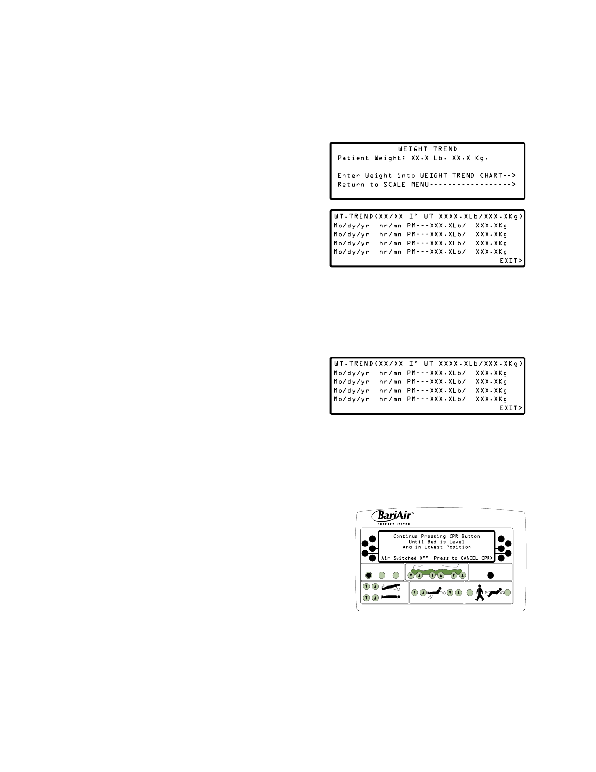
Store Trend
Use store trend to view the patient’s current weight and to enter the date, time and patient’s weight into the weight
trend chart.
1. With Scale menu showing, press Store Trend button.
The display shown at right will appear.
2. Press Weight Trend Chart button to enter current date,
time and displayed weight into the weight trend chart. The
display shown at right will appear.
3. Press Exit button to exit weight trend chart and return
to the Scale menu.
Weight Trend Chart
Use weight trend chart to view the initial weight value as well as the date, time and weight value of the four most recent
weight readings.
1. With Scale menu showing, press Show Chart button.
The display shown at right will appear.
NOTE: To save a weight reading into the weight trend chart,
use DELAY or STORE TREND on the Scale menu.
• The top line of the weight trend chart will display the
date and initial weight entered during patient placement. This line is for reference and will not change.
• The most recent weight reading will appear on the bottom line of the display. This information will move up
one line each time a new weight reading is saved into the weight trend chart and will eventually move up
and off the display.
CPR
1. Press and hold red CPR button on main control panel until
cushions deflate and bed is level and in lowest position.
The display shown at right will flash until bed is in lowest
level position.
AIR ADJUST
FOOT
HEAD
2. Lower side rails.
ALARM
AIR
SCALE
SILENCE
ON/OFF
TREND
BED
3. Begin CPR. Use of crash board is discretionary.
4. After CPR, when patient is clinically stable:
• Raise and lock side rails unless decision has been made to not use side rails (see Safety Information).
• Press the Press to Cancel CPR button on main control panel. Pulsation will resume to previous status.
• Activate Turn Assist and percussion as required.
38
CPR
PATIENT
EXIT
CARDIAC
CHAIR
Page 47

Auxiliary CPR
If main control panel is blank and bed does not respond to red CPR button:
1. Locate service switches in base cover on patient right side.
L
O
C
K
O
2. Press CPR rocker switch to turn air off and
deflate cushions.
U
T
HI–LO FOOT
LOCK
FOOT HEAD HI–LO HEAD
3. Press bed positioning rocker switches to level and
lower bed.
4. Lower side rails.
5. Begin CPR. Use of crash board is discretionary.
PRESS FOR
RAPID
DEFLATE
CPR Switch
C
P
R
Head of Bed
6. After CPR, when patient is clinically stable:
• Raise and lock side rails unless decision has been made to
not use side rails (see Safety Information).
• Call ArjoHuntleigh.
Service
Switches Box
NOTE:COSMETIC COVER
REMOVED FROM DRAWING FOR
IMPROVED CLARITY
Transport Mode
Transport mode will activate automatically if power fails or if the power cord is unplugged from the wall outlet while the bed
is still in operation.
1. Unplug power cord from wall outlet. Store cord by wrapping
it around power cord hangers on base cover. The display
shown at right will appear and flash.
• An approximate percentage of reserve power remaining
will count down in display.
• A low beep will sound when the bed is unplugged and will sound again every minute until battery back-up
is canceled.
• The bed will provide static air support for approximately 60 minutes (one hour). Use of bed functions (head
up / down, foot up / down, bed up / down, etc.) will decrease reserve power more rapidly than static air
support.
• Static air support will not be deactivated during the battery back-up.
NOTE: The bed will shut off automatically after one hour if the bed is unplugged with air off and the display on.
To restart the bed, plug the power cord into a wall outlet.
NOTE: Plug power cord into a wall outlet immediately if
the Transport Mode display at right appears. Less
than ten minutes of reserve power is left. It will
take approximately four hours to fully recharge
the battery. A protection circuit helps protect the
battery from overcharging.
39
Page 48

2. Plug power cord into a wall outlet to end transport mode when destination is reached.
NOTE: If Turn Assist was on before bed was unplugged, five beeps will sound and the Turn On Turn Assist? display will
appear to prompt the caregiver to reactivate Turn Assist. Pulsation will be restored if it was activated before bed
was unplugged. Reactivate exit alarm from the Scale menu.
Hand Control
A hand control is available to provide the patient with bed positioning options.
HEAD UP / DOWN
Adjusts head of bed
from level to +50˚
FOOT UP / DOWN
Adjusts foot of bed
from level to 72˚ angle
of support.
CAUTION WHEN RAISING HEAD
WITH INFLATABLE OVERLAYS
USE FULL TRENDELENBURG TO PREVENT SLIDING
306589
angle of support.
WARNING
Unplug hand control and do not use when using oxygen. Use of hand
control in an oxygen‑enriched environment may produce potential of
fire hazard. This equipment is not suitable for use in the presence of a
flammable anesthetic mixture with air, with oxygen or nitrous oxide.
40
Page 49

Power Down Procedure
1. Adjust bed to lowest position.
2. Allow batteries to charge fully.
3. Unplug power cord from wall outlet. The display shown
at right will appear and flash.
4. Press Cancel button to deactivate battery back-up
power to allow for bed storage.
5. Wrap power cord around power cord hangers on base cover.
NOTE: When in storage the bed must be plugged into a wall outlet to maintain battery charge.
41
Page 50

SPECIFICATIONS*
Maximum recommended patient weight, including accessories .............................................. 850 lb (386 kg)
Trapeze accessory static weight capacity designed for patients weighing up to 850 lb (386 kg patient)
Mattress ......................................................................................................................................................................................................................................................
Overall dimensions (L x W) ........................................................................................................................ 80 in L x 36 in W (203 cm x 91 cm)
Bed Width ..................................................................................................................................................................................................................................................
Overall: .................................................................................................................................................................................................................................................
With side rails in narrow door position ..........................................................................................................................40.25 in (102 cm)
With side rails in normal up / down position .............................................................................................................43.25 in (110 cm)
With Side rails in extended up / down position .......................................................................................................53.25 in (135 cm)
With adjustable corner posts in extended position ...............................................................................................59.75 in (152 cm)
Head ......................................................................................................................................................................................................................................................
Normal ......................................................................................................................................................................................................... 36 in (91 cm)
Extended ................................................................................................................................................................................................. 45 in (114 cm)
Seat
Normal ......................................................................................................................................................................................................... 36 in (91 cm)
Extended ................................................................................................................................................................................................. 45 in (114 cm)
Leg
Normal ......................................................................................................................................................................................................... 33 in (84 cm)
Extended ................................................................................................................................................................................................. 44 in (112 cm)
Bed Length ...............................................................................................................................................................................................................................................
Overall ................................................................................................................................................................................................................. 89 in (226 cm)
Patient surface ............................................................................................................................................................................................... 80 in (203 cm)
Patient surface extended (foot board down) ............................................................................................................................. 94 in (239 cm)
Radiolucency ..........................................................................................................................................................................................................................................
Material ............................................................................................................................................................................................................................Phenolic
Window size (L x W)..........................................................................................................................................34 in L x 31 in W (86 cm x 79 cm)
Bed Weight ...............................................................................................................................................................................................................................................
Total weight (includes both frame and mattress) ....................................................................................... Approximately 1210 lb (550 kg)
Bed Height (to Hard Pan Surface) .........................................................................................................................................................................................
Low.................................................................................................................................................................................................................... 21.25 in (54 cm)
High ..................................................................................................................................................................................................................... 27.5 in (70 cm)
Side Rails ....................................................................................................................................................................................................................................................
Length ................................................................................................................................................................................................................. 48 in (122 cm)
Height from floor (in up position) ......................................................................................................................................................47 in (120 cm)
Height from floor (in down position) .................................................................................................................................................27 in (69 cm)
Scale
Repeatability ......................................................................................................................................................................................................................99.3%
Accuracy ....................................................................................................................................................................................+ / - 1.0% patient weight
42
Page 51

Bed Function Articulation
Fowler ........................................................................................................................................................................................................................................... 65°
Trendelenburg ........................................................................................................................................................................................................14° + / - 2°
Reverse Trendelenburg......................................................................................................................................................................................14° + / - 2°
Leg .................................................................................................................................................................................................................................................. 72°
Cardiac Chair:
Head ....................................................................................................................................................................................................................................25°
Foot......................................................................................................................................................................................................................................30°
Trendelenburg ..............................................................................................................................................................................................................14°
Patient Exit:
Head .................................................................................................................................................................................................................60° + / - 10°
Foot...................................................................................................................................................................................................................70° + / - 10°
Reverse Trendelenburg ...........................................................................................................................................................................14° + / - 2°
Electrical
Voltage ..........................................................................................................................................................................................110 / 115 VAC (230 VAC)
Frequency ................................................................................................................................................................................................. 60 Hz (50 / 60 Hz)
Ampere rating: ................................................................................................................................................................................................................................
Normal operating .............................................................................................................................................................................. 4.5 (2.5) Amps
All circuits energized / maximum operating ......................................................................................................................... 12 (6) Amps
Start up of all circuits ................................................................................................................................................................................... 15 Amps
Maximum electrical leakage ........................................................................................................................................Less than 100 Microamps
Ground resistance ....................................................................................................................................................................Less than 0.1 Milliohms
Noise level....................................................................................................................................................................................................56 dB at 1 meter
Power cord (110V) ............................................................................................................................................ 14 ft 6 in (441 cm) hospital grade
Power cord (230V) ........................................................................................................................................... 10 ft 9 in (327 cm) hospital grade
Environmental Storage / Transport Conditions
Temperature range ................................................................................................................................................................................................. 0 to 60°C
Relative humidity range .....................................................................................................................................................................................10 to 90%
Atmospheric pressure range ............................................................................................................................................................500 to 1060 hPa
Environmental Operating Conditions
Temperature range ...................................................................................................................................................................................... +10 to + 40°C
Relative humidity range .....................................................................................................................................................................................30 to 70%
Atmospheric pressure range ............................................................................................................................................................500 to 1060 hPa
Classification
Equipment not suitable for use in the presence of a flammable anesthetic mixture with air, oxygen or nitrous
oxide
Continuous Operation
Type B Equipment
Class 1 Equipment
Ordinary Equipment
* Specifications are subject to change.
43
Page 52

ELECTROMAGNETIC COMPATIBILITY EMC
Although this equipment conforms to the intent of the 2004/108/EC EMC Directive, all medical equipment may
produce electromagnetic interference or be susceptible to electromagnetic interference. The following are guidance
and manufacturer’s declarations regarding electromagnetic compatibility for the BariAir Therapy System.
• The BariAir Therapy System needs special precautions regarding EMC and should be installed and put into service
according to the EMC information provided in the following pages.
• Portable and mobile RF communications equipment can affect the performance of the BariAir Therapy System.
Please use the guidelines and recommendations specified in Table 4 and Table 6.*
• Other medical equipment or systems can produce electromagnetic emissions and therefore can interfere with the
functionality of the BariAir Therapy System. Care should be used when operating the BariAir Therapy System adjacent
to other equipment. If adjacent use is necessary, the BariAir Therapy System should initially be observed to verify
normal operation in the configuration in which it will be used.
• The electrical cables, external power supplies and accessories listed or referenced in this manual have been shown
to comply with the test requirements listed in the following tables. Care should be taken to use only manufacturerrecommended cables, power supplies and accessories with the BariAir Therapy System.
If a third-party supplier offers cables, external power supplies and electrical accessories for use with the BariAir
Therapy System product and they are not listed or referenced in this manual, it is the responsibility of that thirdparty supplier to determine compliance with the standards and tests in the following tables.
*Note: If using IEC 60601-1-2, Edition 2.1, Table 201, Table 204 and Table 206
Table 1 [IEC 60601‑1‑2, Edition 3.0 / Table 201 [IEC 60601‑1‑2, Edition 2.1]
Guidance and Manufacturer’s Declaration ‑ Electromagnetic Emissions
The BariAir Therapy System is intended for use in the electromagnetic environment specified below. The customer or the end user of the BariAir
Therapy System should ensure that it is used in such an environment.
Emissions Test Compliance Electromagnetic Environment ‑ Guidance
RF Emissions
CISPR 11
RF Emissions
CISPR 11
Harmonic Emissions
EN / IEC 61000-3-2
Voltage Fluctuations / Flicker Emissions
EN / IEC 61000-3-3
Group 1 The BariAir Therapy System uses RF energy only for its internal function.
Therefore, its RF emissions are very low and are not likely to cause any
interference in nearby electrical equipment.
Class B
The BariAir Therapy System is suitable for use in all establishments,
Class A
Complies
including domestic establishments and those directly connected to the
public low-voltage power supply network that supplies buildings used
for domestic purposes.
44
Page 53

Table 2 [IEC 60601‑1‑2, Edition 3.0 / Table 204 [IEC 60601‑1‑2, Edition 2.1]
Guidance and Manufacturer’s Declaration ‑ Electromagnetic Immunity
The BariAir Therapy System is intended for use in the electromagnetic environment specified below. The customer or the end user of the BariAir
Therapy System should ensure that it is used in such an environment.
Immunity Test EN / IEC 60601 Test
Level
Electromagnetic Discharge (ESD)
EN / IEC 61000-4-2
Electrical Fast Transient / Burst
EN / IEC 61000-4-4
Surge
EN / IEC 61000-4-5
Voltage dips, short interruptions and
voltage variations on power supply input
lines
EN / IEC 61000-4-11
Power frequency (50 / 60 Hz) magnetic
field
EN / IEC 61000-4-8
NOTE: UT is the a.c. mains voltage prior to application of the test level.
± 6kV Contact
± 8kV Air
± 2kV for power supply
lines
± 1kV for input / output
lines
± 1kV line(s) to line(s)
± 2kV line(s) to earth
<5% UT (>95% dip in UT)
for 0,5 cycle
40% UT (60% dip in UT)
for 5 cycles
70% UT (30% dip in UT)
for 25 cycles
<5% UT (>95% dip in UT)
for 5 seconds
3A/m 3A/m Power frequency magnetic fields should
Compliance
Level
± 6kV Contact
± 8kV Air
± 2kV for power supply
lines
± 1kV for input / output
lines
± 1kV differential mode
± 2kV common mode
<5% UT (>95% dip in UT)
for 0,5 cycle
40% UT (60% dip in UT)
for 5 cycles
70% UT (30% dip in UT)
for 25 cycles
<5% UT (>95% dip in UT)
for 5 seconds
Intended Electromagnetic
Environment
Floors should be wood, concrete or
ceramic tile. If floors are covered with
synthetic material, the relative humidity
should be at least 30%.
Mains power quality should be that
of a typical commercial or hospital
environment.
Mains power quality should be that
of a typical commercial or hospital
environment.
Mains power quality should be that
of a typical commercial or hospital
environment. If the user of the BariAir™
Therapy System requires continued
operation during power mains
interruptions, it is recommended that
the BariAir™ Therapy System be powered
from an uninterruptible power supply or
a battery.
be at levels characteristic of a typical
commercial or hospital environment.
45
Page 54

Table 4 [IEC 60601-1-2, Edition 3.0 / Table 204 [IEC 60601-1-2, Edition 2.1]
Guidance and Manufacturer’s Declaration ‑ Electromagnetic Immunity
The BariAir Therapy System is intended for use in the electromagnetic environment specified below. The customer or the end user of the BariAir
Therapy System should ensure that it is used in such an environment.
Immunity Test EN / IEC 60601 Test
Level
Compliance
Level
Intended Electromagnetic
Environment
Portable and mobile RF communications
equipment should be used no closer to
any part of the BariAir Therapy System,
including cables, than the recommended
separation distance calculated from the
equation applicable to the frequency of
the transmitter.
Recommended separation distance
Conducted RF
EN / IEC 61000-4-6
Radiated RF
EN / IEC 61000-4-3
NOTE 1: At 80 MHz and 800 MHz, the higher frequency range applies.
NOTE 2: The guidelines may not apply in all situations. Electrmagnetic propagation is affected by absorption and reflection from objects,
structures and people.
a
Field strengths from fixed transmitters, such as base stations for radio (cellular / cordless) telephones and land mobile radios, amateur radio,
AM and FM radio broadcast and TV broadcast cannot be predicted theoretically with accuracy. To assess the electromagnetic environment
due to fixed RF transmitters, an electromagnetic site survey should be considered. If the measured field strength in the location in which the
BariAir Therapy System is used exceeds the applicable RF compliance level above, the BariAir Therapy System should be observed to verify normal
operation. If abnormal performance is observed, additional measures may be necessary, such as re-orienting or relocating the BariAir Therapy
System.
b
Over the frequency range 150 kHz to 80 MHz, field strengths should be less than 3V/m.
3Vrms
150 kHz to 80 MHz
3V/m
80 MHz to 2,5 GHz
3Vrms
150 kHz to 80 MHz
3V/m
80 MHz to 2,5 GHz
d = 1,2√P
d = 1,2√P 80 MHz to 800 MHz
d = 2,3√P 800 MHz to 2,5 GHz
where P is the maximum output power
rating of the transmitter in watts (W)
according to the transmitter manufacturer
and d is the recommended minimum
separation distance in meters (m).
Field strengths from fixed RF transmitters,
as determined by an electromagnetic
site surveya, should be less than the
compliance level in each frequency rangeb.
Interference may occur in the vicinity of
equipment marked with the following
symbol:
46
Page 55

Table 6 [IEC 60601‑1‑2, Edition 3.0 / Table 206 [IEC 60601‑1‑2, Edition 2.1]
Recommended Separation Distances Between Portable and Mobile RF Communication Equipment and the BariAir
The BariAir Therapy System is intended for use in an electromagnetic environment in which radiated RF disturbances are controlled. The
customer or the user of the BariAir Therapy System can help prevent electromagnetic interference by maintaining a minimum distance between
the portable and mobile RF communications equipment (transmitters) and the BariAir Therapy System as recommended below, according to the
maximum output power of the communications equipment.
Rated Maximum Output Power
of Transmitter
(W)
0.01 0,12 0,12 0,23
0.1 0,38 0,38 0,73
1 1,2 1,2 2,3
10 3,8 3,8 7,3
100 12 12 23
For transmitters rated at a maximum output power not listed above, the recommended separation distance d in meters (m) can be estimated
using the equation applicable to the frequency of the transmitter, where P is the maximum output power rating of the transmitter in watts (W)
according to the transmitter manufacturer.
NOTE 1: At 80 MHz and 800 MHz, the separation distance for the higher frequency range applies.
NOTE 2: These guidelines may not apply in all situations. Electromagnetic propagation is affected by absorption and reflection from structures,
objects and people.
150 kHz to 80 MHz
d = 1,2√P
Therapy System
Separation Distance According to Frequency of Transmitter
(m)
80 MHz to 800 MHz
d = 1,2√P
800 MHz to 2,5 GHz
d = 2,3√P
47
Page 56

DEFINITIONS OF SYMBOLS USED
XXX lb
XXX kg
Type B Equipment
Alternating Current
The BariAir Therapy System is in conformity with the Medical Devices
0086
Directive (93/42/EEC) and has been subject to the conformity
assurance procedures laid down in the Council Directive.
Maximum Safe Working Load
Manufacturer
Dangerous Voltage
Attention, Consult Accompanying Documents
CUSTOMER CONTACT INFORMATION
For questions regarding this product, supplies, maintenance or additional information about ArjoHuntleigh products
and service, please contact an ArjoHuntleigh authorized representative or visit www.ArjoHuntleigh.com.
In the US, call 1-800-343-0974.
® and ™ are trademarks belonging to the ArjoHuntleigh group of companies
© ArjoHuntleigh 2014. P/N 404832-AH Rev A 06/2014
48
Page 57

49
Page 58

Page 59

Page 60

0086
www.ArjoHuntleigh.com
Manufactured for:
ArjoHuntleigh AB
Hans Michelsensgatan 10
211 20 Malmö, Sweden
 Loading...