


 Loading...
Installationinstructions |
Decomat 8666 |
INSTALLATION |
INSTRUCTIONS |
Decomat |
8666 |
9908
Serial no. 81511-
4996859-04
|
1999 |
0301 |
Produced: |
|
1 |

Decomat 8666 |
Installationinstructions |
Contents
Safety rules ________________________________________________ 3
General safety rules _______________________________________ 3
Power cut-off device ______________________________________ 3
Caution symbols _________________________________________ 3
Installation ________________________________________________ 4
Wall-mounted model ______________________________________ 5
Electric connections ______________________________________ 6
Connection of water, steam, drain and dryer ____________________ 7
Functional check _________________________________________ 9
Technicaldata _____________________________________________ 10
Electric circuit diagram _____________________________________ 11
9908
2
Installationinstructions |
Decomat 8666 |
|
|
Safety rules
This machine is designed with a number of integrated safety devices. To avoid personal injury it is essential that the safety devices are not bypassed or in any other way put out of action.
General safety rules
•The machine should be connected according to the instructions.
•The machine may not by used by juveniles.
•Installation work and servicing should be carried out by staff trained to use this machine.
•The door switch on the machine may not be bypassed under any circumstances.
•Leakage in the system, eg, due to worn lid gasket, must be repaired immediately.
•Personnel concerned must study valid handbooks and service manuals prior to any repairs or service work.
•All plug-in leads must be unplugged from all of the circuit boards of the control system before any welding on or close to the dishwasher is started.
•The machine may not be sprayed with water.
•Caution must be observed when using corrosive detergents.
•Safety precautions must be observed when using hot water or steam.
Power cut-off device
The machine can be provided with a separate main switch in the power supply line, easily accessible on the wall.
Caution symbols
This manual contains certain warnings, instructions and advice of such importance that they are particularly emphasized. The configuration and use of the appertaining symbols are as follows:
This symbol indicates a warning in the text. It gives warning of dangers which could lead to minor or major injury to the person and even to a fatality.
It is also used in warnings to avoid damage to the machine.
9908
3

Decomat 8666 |
Installationinstructions |
|
|
|
|
Installation
•Pull the machine (standing on a transport pallet) to where it is to stand.
•Lift the machine from the transport pallet.
•Place the machine in position and set the adjusting screws of the feet to make the machine stand firm and level. Check with a spirit level as shown in figure 1 to ensure that the machine is level.
•The floor on which the machine is to stand must be horizontal and smooth.
Fig. 1. Adjusting
V769
If the machine is to be moved using a fork-lift truck:
•Position the forks of the truck as illustrated in figure 2 so as not to damage the machine.
Fig. 2. Positioning the fork-lift forks.
 Bottom frame
V318
9908
4
Installationinstructions |
Decomat 8666 |
|
|
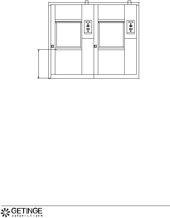
Wall-mounted model
•If the machine is fitted with two doors and is to be installed in a wall, the clearance between wall and machine must be at least 25 mm.
•If several machines are mounted in-line, they must be adjusted to the same height when being installed (especially important when a loading trolley is used)
•If a plinth plate is used, the height from the floor to the bottom of the machine must be at least 100 mm.
•Set the adjusting screws on the feet to make the machine stand firm and level. Check with a spirit level on the sides of the machine.
•The floor in front of all the machines must be level and smooth to ensure that the loading trolley works satisfactorily.
800
V768
50
Clena side |
Soiled side |
1895 |
1870 |
|
>100 |
V398
Fig. 3. Installed in wall
9908
5
Decomat 8666 |
Installationinstructions |
|
|
|
|
Electric connections
Installation may be made by authorized personnel only.
•The machine can be provided with a separate main switch, with a 3 mm gap, in the power supply line to facilitate maintenance and service.
•Position the disconnecting switch easily accessible on the wall.
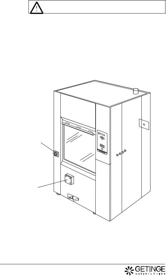
Electrical connections on the main switch located on the front of the machine are made as follows:
•The disinfector is connected to protective earth and to the supply voltage indicated on the data plate.
•Ensure that the correct size of fuse is fitted. The fuse value is stated on the data plate.
Main switch
Electrical connection
V770
Fig. 4. Electrical connection (see electric circuit diagram in the service instructions)
9908
6
Loading...