

SERVICE INSTRUCTIONS
Washer-disinfector
46-2,46-4,46-5
Mfg. no. SEV0440130-
5019675-00

Service documentation
The 46 series
Safety regulations
T echnical data
Description
Software description and
settings
Preventive maintenance
Fault indications and
troubleshooting
Repair and adjustment
We reserve the right to change our design and
material specifications without prior notice.
5019675-00 2004-10-05


Safety regulations
Safety regulations
Contents
Safety regulations __________________________________________3
General safety regulations __________________________________ 3
Product liability __________________________________________ 3
Isolator switch ___________________________________________ 3
Attention symbols ________________________________________ 3
Service instructions
5019675-00Edition 0410

Safety regulations
5019675-00 Edition 0410
Service instructions

Safety regulations
This machine is designed with a number of built-in safety devices. To avoid injury, it is very
important that these safety devices are not bypassed and thus disabled.
General safety regulations
• Take care when handling the chemical detergent used in the machine. Read the details on the
container or contact the manufacturer:
- if detergent comes into contact with operator’s eyes or skin or if the vapours are breathed
in, etc.
- about storing the detergent and disposing of empty containers.
• The machine must be connected in accordance with the installation instructions.
• The machine must only be operated by adults.
• Installation and service work must be done by personnel trained for this machine.
• Never bypass the door switch of the machine.
• Leakage in the system, for example at a worn door seal, must be repaired immediately.
• Before repair or servicing work is done, the personnel concerned must study the relevant
manuals.
• Before welding begins on or close to the machine, all wiring connected by plugs and sockets
must be disconnected from all circuit boards in the machine.
• The machine must not be hosed down with water.
• Take care when using corrosive detergents.
• Precautionary measures for hot water and steam.
• Run a process before starting servicing. If this is not possible, disinfect the machine with
disinfectant before starting servicing.
Safety regulations
Product liability
Modifications to the equipment made without the approval of the manufacturer, or incorrect
use, invalidate the manufacturer’s product liability.
Isolating device
The machine must always be fitted with a separate isolating device in the power supply,
mounted in an easily accessible position on the wall.
Attention symbols
Some of the warnings, instructions and advice in this manual are so important that we used the
following special symbols to draw attention to them. The symbols and designs used are:
This symbol indicates a warning in the text of the manual. Injury or even death
may result if you do not heed it.
It also highlights warnings to avoid damage to equipment.
This symbol highlights a warning in the text of the manual dealing with the
handling of components sensitive to ESD. The hazard that it warns about may
result in damage to hardware and/or circuit boards.
Service instructions
5019675-00Edition 0410


Technical data
Contents
Technical data______________________________________________3
Alternative connection arrangements ___________________________4
Technical data
Service instructions
5019675-00Edition 0410

Technical data
5019675-00 Edition 0410
Service instructions

Technical data
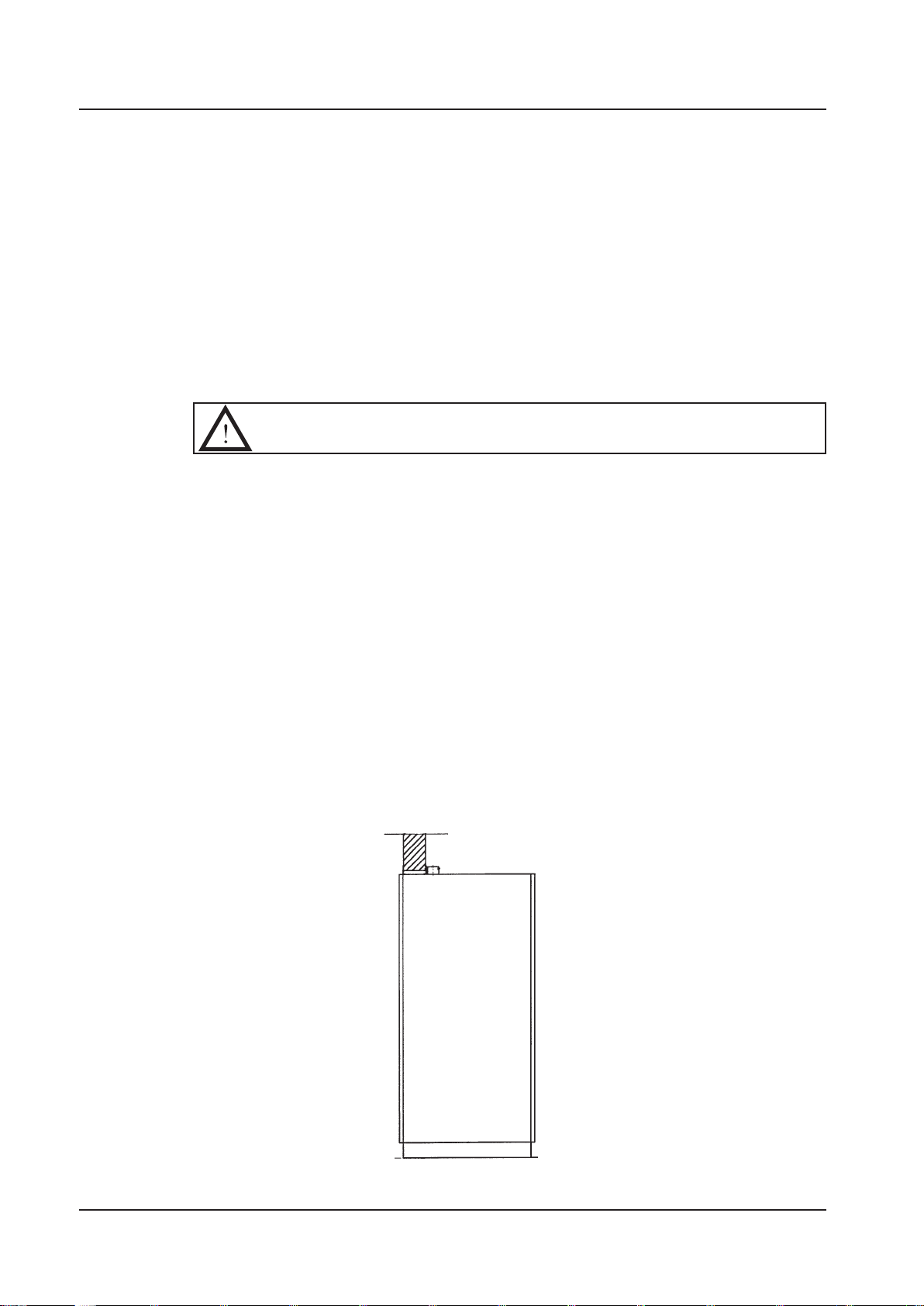
Important
Width 650 mm
Depth 690 mm
Height
Chamber size
Technical data
Machine 46-2 without dryer 1 5 0 kg
Machine 46-2 with dryer 1 50 k g
Machine 46-4 without dryer 1 5 0 kg
Machine 46-4 with dryer 1 80 k g
Machine 46-5 without dryer 1 5 5 kg
Machine 46-5 with dryer 1 85 k g
Machine 46-2 without dryer 1600 mm
Machine 46-2 with dryer 1600 mm
Machine 46-4 without dryer 1600 mm
Machine 46-4 with dryer 1860 mm
Machine 46-5 without dryer 1670 mm
Machine 46-5 with dryer 1930 mm
Machine 46-2, 46-4 H=590mm, W=550mm, D=620mm
Operational volume 201 litres
Total volume 280 litres
Machine 46-5 H=660mm, W=550mm, D=620mm
Operational volume 225 litres
Total volume 305 litres
Environmental requirements:
Air humidity max 80% at 31 °C
Room temperature: 5 - 40 °C
Water consumption approx 15 litres/phase
Cold water
Connection 15 (1/2") mm
Pressure 100-800 kPa
Flow rate min 20 l/min
Hot water
Temperature 45-60 °C
Connection 15 (1/2") mm
Pressure 100-800 kPa
Flow rate min 20 l/min
Dist./de-ion. water
Connection 20 (3/4") mm
Pressure 50-900 kPa (if the pressure is below 50 kPa a separate
feed pump must be connected)
Flow rate min 20 l/min
Steam
Connection 15 (1/2") mm
Pressure 300-500 kPa
Consumption 0. 5 kg/min at 300 kPa
Waste, water ø 50 mm Capacity 30 l/min
Waste, air ø 63 mm 125-150 m
40 sec<
Max outside temperature 5 0 °C
Sound level 60 dB (A)
Elec. supply arrangements See Alternative connection
3
/h 35°C, Humidity 100%
40% after 2 min.
Service instructions
5019675-00Edition 0410
Technical data
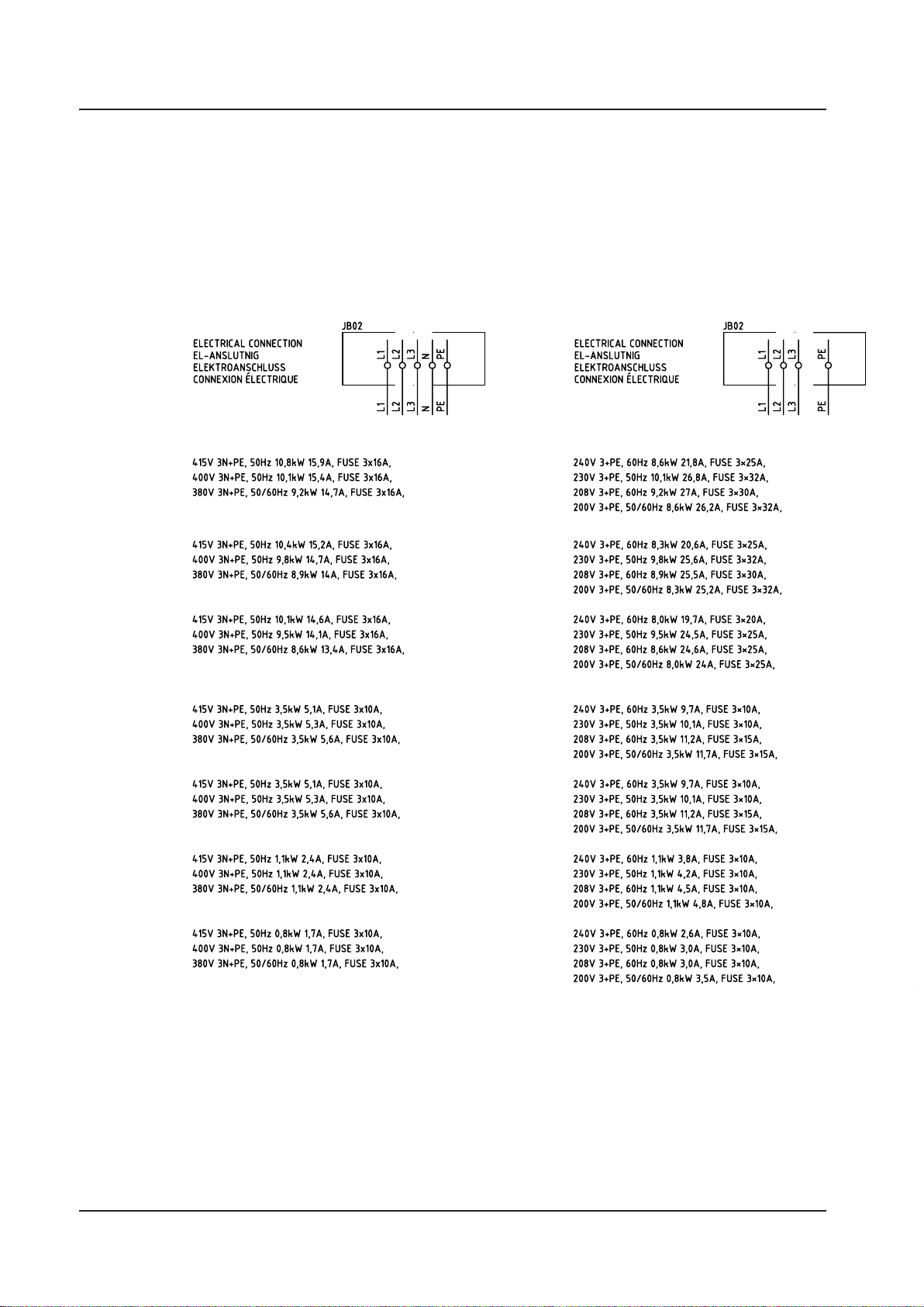
Alternative connection arrangements
46-5
Electric
heater
46-4
Electric
heater
46-2
Electric
heater
46-5
Steam
heater
with dryer
46-4
Steam
heater
with dryer
46-5
Steam
heater
without dryer
46-4
Steam
heater
without dryer
5019675-00 Edition 0410
Service instructions

Description
Contents
General ___________________________________________________3
Schem atic diagr am __________________________________________4
46-2 ___________________________________________________ 4
46-4, -5 _________________________________________________ 5
Safe and simple _____________________________________________6
Simple service and installation ________________________________6
Description
Door operation _____________________________________________6
Dosing system___________________________________________ 7
Drying (option 46-4, -5) ______________________________________8
Single drying (option 46-2) ___________________________________8
Programs _________________________________________________9
Abort at start of process __________________________________ 10
Aborting an ongoing process ______________________________ 10
Fast-stepping a program __________________________________ 11
Service instructions
5019675-00Edition 0410

General
Description
The Getinge 46-Series are large capacity Washer Disinfectors for cleaning,
disinfection and drying of moisture and temperature stable Surgical Instruments
(rigid and tubular), Hollow ware, Glass ware, Baby bottles, Suction bottles, Wash
bowls, Containers and for 46-4 and 46-5 also Anesthetic accessories.
The machine has spray arms and dockings:
• 46-2 has three spray arms and one docking:
• 46-4 has two spray arms and two dockings:
• 46-5 has two spray arms and three dockings:
The machine can be equipped with several different accessories for different cleaning
requirements. These accessories are presented in a special accessories catalogue.
There are several possible ways of installing and equipping the machine
depending on its field of application:
• 46-2 has electrical heating. 46-4 and 46-5 have electric or steam heating
• 46-2 is fitted with a single door. 46-4 and 46-5 are fitted with a single or double
door
.
• Connection of distilled or de-ionised water.
• Extra dosing pumps which allow chemical disinfection of heat-sensitive
goods.
• With or without built-in drying system.
• Audible signal on process complete, fault code, etc.
The washer-disinfector has been tested and approved to ISO 15883.
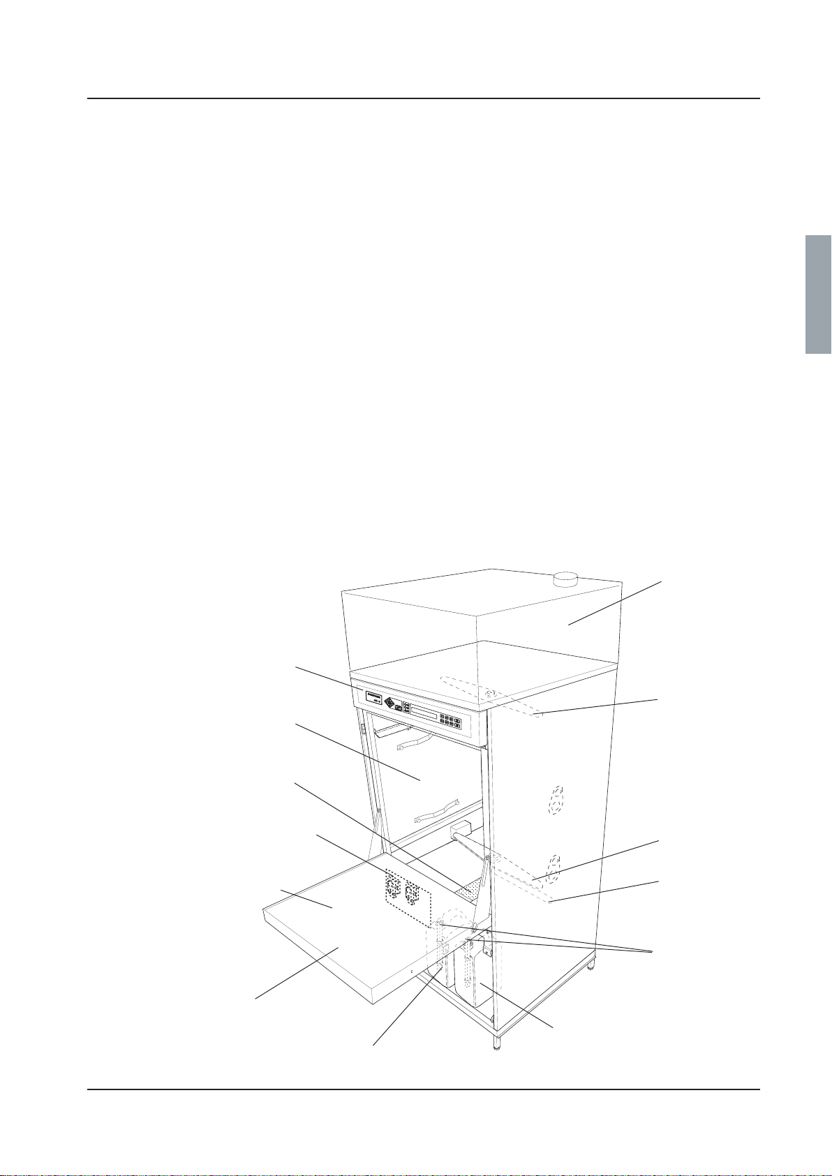
.
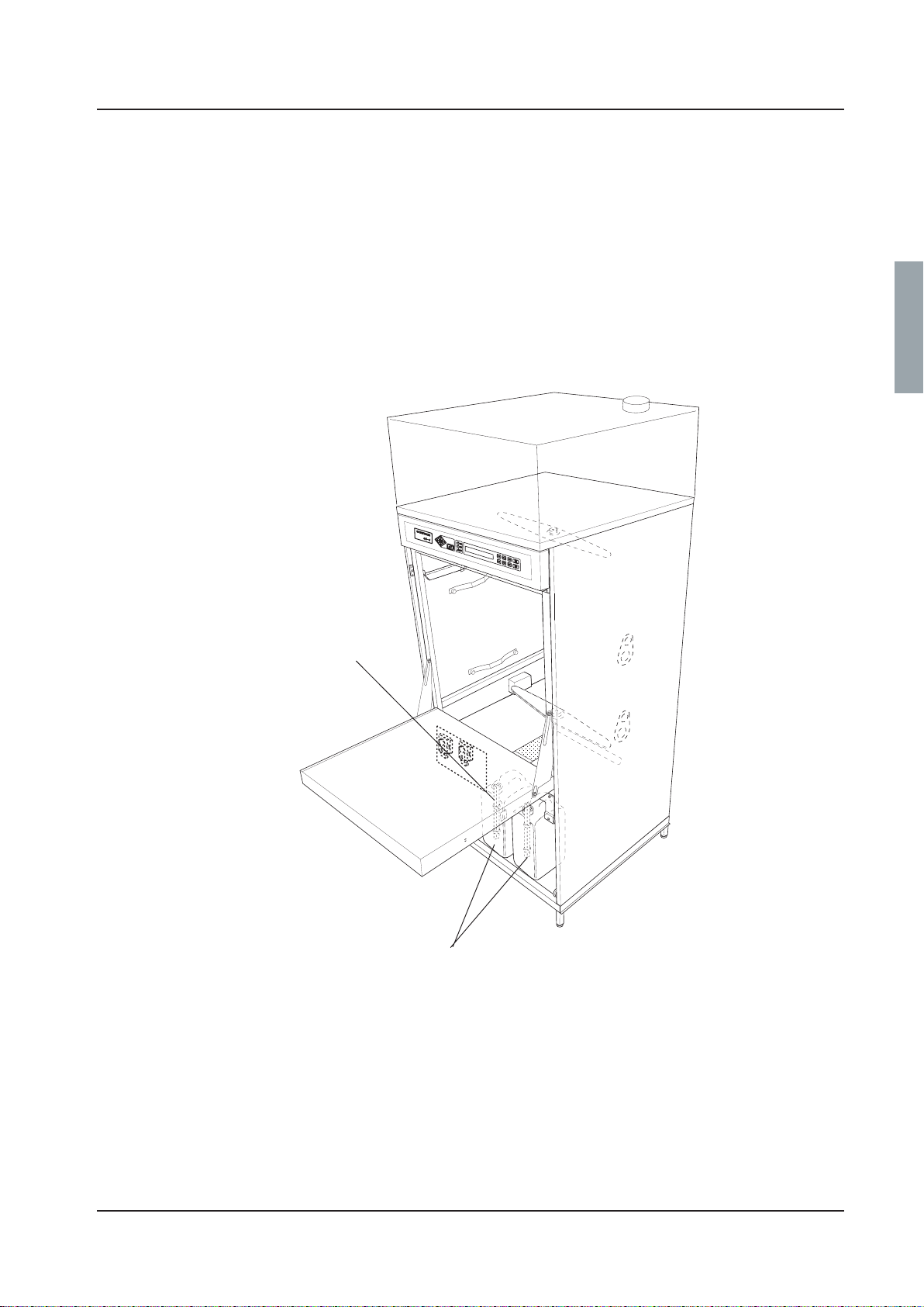
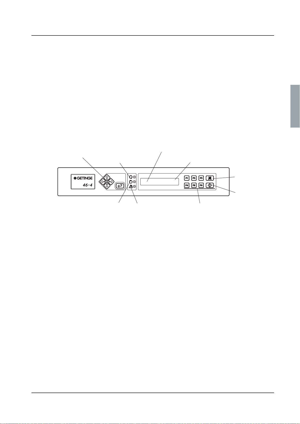
The control panel
Washing
chamber
Bottom strainer with
handle
Dosing pumps
Hinged door
Door lock
(electrically interlocked)
Container for alkaline
detergent
Dryer module
Upper spray arm
Lower spray wing
Lower spray arm
Suction pipe with
container alarm
V1627
Container for rinse-aid
or acid detergent
Service instructions
5019675-00Edition 0410

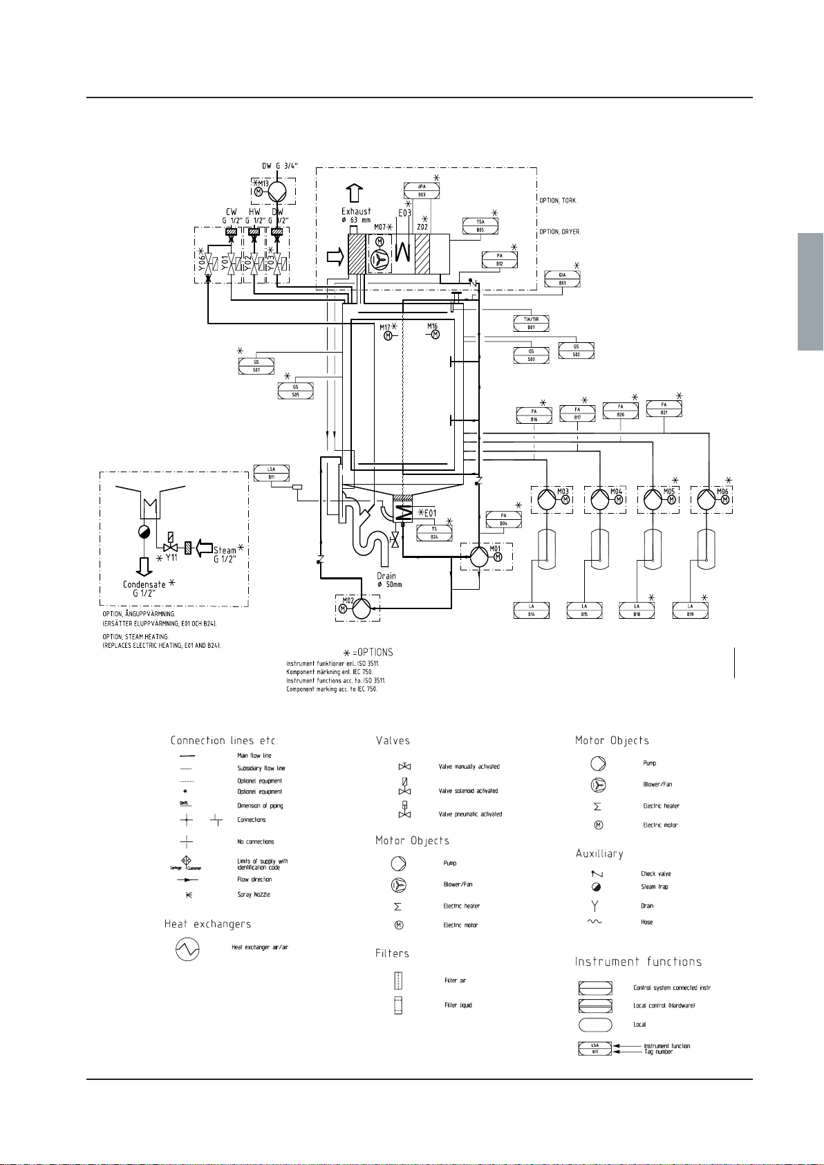
Schematic diagram
46-2
Description
5019675-00 Edition 0410
Service instructions
46-4, -5
Description
V1560
Service instructions
5019675-00Edition 0410
Description
Safe and simple
The disinfector is controlled by a microprocessor. This has several advantages:
• the built-in service program makes troubleshooting and servicing far easier
• safety and reliability can be kept high by continuous monitoring of the process
• the dosing of detergent, the temperature and the disinfection time can all be altered with
great precision to suit different conditions.
The programs can be adapted precisely to suit the needs of each user. Existing programs can be
re-programmed via a PC. As standard, the washer-disinfector has two to six programs.
The door and wash chamber are well insulated, so that the washer-disinfector is energyefficient and silent in operation.
Operation is simple and the control buttons are few and clearly marked.
Programming may only be done by authorised personnel.
Simple service and installation
Valves and electrical equipment are easily accessible from the front for inspection and service.
Door function
46-2 is fitted with a single door. 46-4 and 46-5 are fitted either with a single door or with double
doors.
Machines with double doors have a system of interlocks to ensure that only one door can be
opened at a time. This means that the clean-side door must be closed before the dirty-side door
can be opened.
When is pressed, the door is locked and a yellow lamp (process running) flashes for about
10 seconds. If you press Vagain during this “cancel time”, the dirty-side door is unlocked and
the door can be opened.
When the program is complete, a green lamp lights up on both sides (if there are double doors)
and the clean-side door is unlocked. When the door has been opened manually, the green lamp
goes out. With double doors, the clean-side door must be closed before the dirty-side door can
be unlocked.
Clean side
Dirty side
V398
5019675-00 Edition 0410
Service instructions
Dosing system
Description
In standard form, the machine has two dosing systems. One is for alkaline
detergent and one is for rinse-aid or acid detergent. The dosing amount can be
set individually for each program.
The machine cannot be started until detergent has been added. If the detergent
bottle is empty ”ADD DETERGENT” appears on the display.
A third and a fourth dosing system for chemical disinfection of heat-sensitive
goods or instrument milk, for example, can be installed.
Empty container
alarm
Container for
detergent/rinse-aid
Service instructions
5019675-00Edition 0410
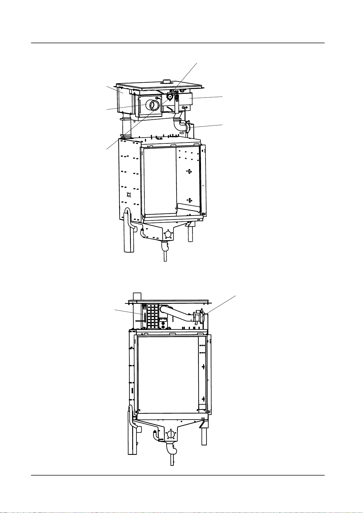
Drying (option 46-4, -5)
Heat
exchangers
Fan
Differential
pressure
switch
Description
Pressure
switch
Filter
Check valve
Single drying (option 46-2)
Fan
Check valve
5019675-00 Edition 0410
Service instructions
Program
Description
The machine has an electronically programmable control system which can hold up to 10-15
programs. Six of these programs can be started with the program selection buttons. With 1-6
you can choose up to six programs. If the control system has more programs, the subsequent
ones are chosen from a scrollable list. You can reach the list of available programs (from
standby mode), by pressing S twice and choosing a program with J or H. Confirm the
chosen program with S .
The machine comes with a number of standard programs in the programmer (see the appendix
for Standard programs). Parameters in these programs can be modified to suit the needs of
Programming buttons
(see “Service instructions”)
Yellow: Process running
V1624
Green: Process complete
individual users. Individual programs can be created with a PC. An entire standard program or
parts of one can be used as a starting point for programming.
Programming may only be done by an authorised service technician.
Programs are chosen with the program selection buttons and the process is started with V
(starting of a process is indicated by the yellow lamp at M flashing for ten seconds and then
going out).
When the process is complete, the green lamp at N lights up and the door can be opened
manually (on a machine with manual door). With an automatic door, the door opens
automatically when the process is complete.
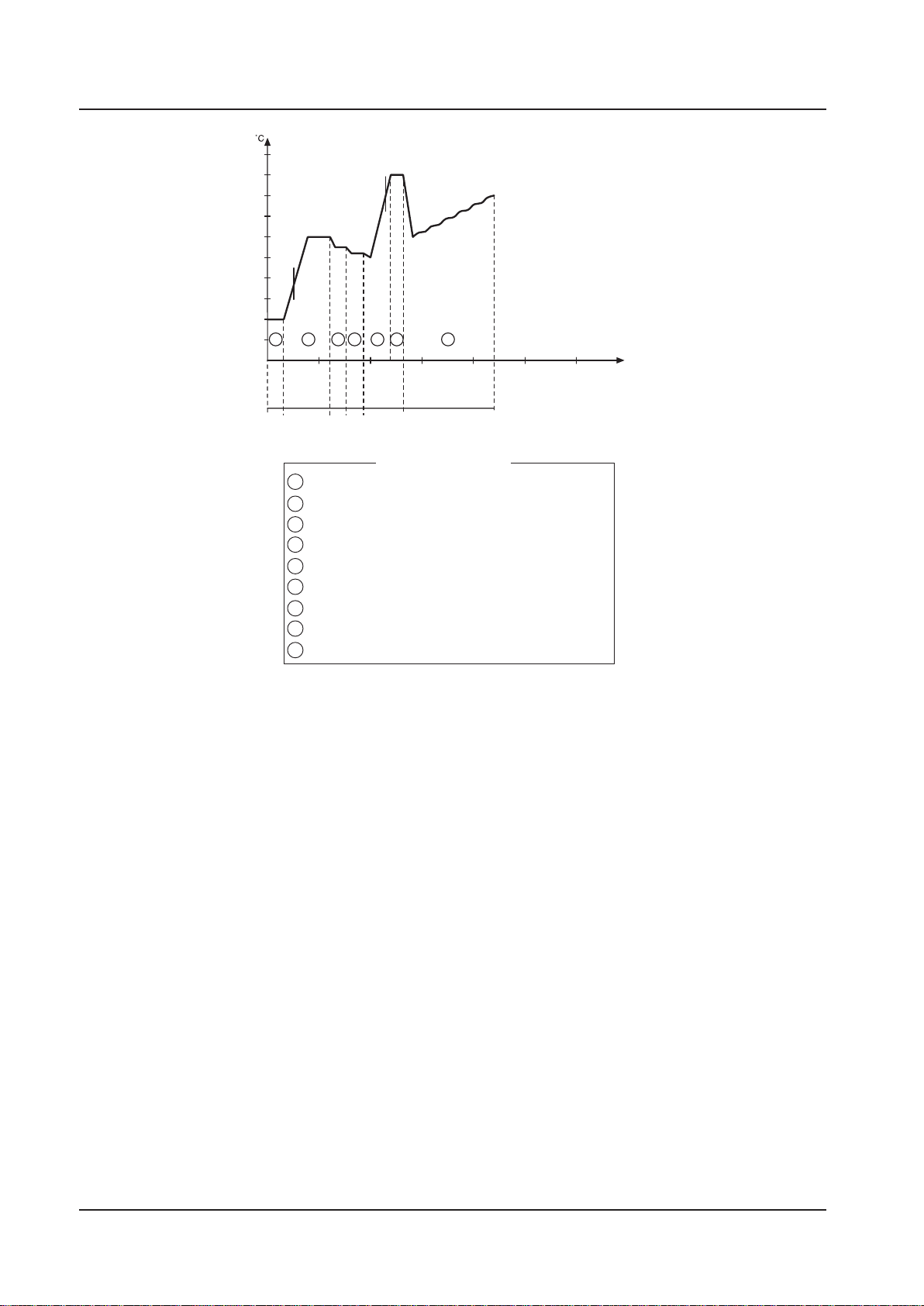
The illustration on the next page shows the program sequence in the OP-D program.
Program number
P01 OP-SHORT-D
47.0 °C
Red: Fault code
Before starting: Chosen program
While running: Program phase (eg
“Rinsing”)
Start wash
program
Program selection buttons
Service instructions
5019675-00Edition 0410
Description
n
100
90
80
70
60
50
A
40
30
20
10
3 861
10 20 30 40 50 60 mi
CW HW HW
HWCW+HW
1 Pre-rinse 1
2 Pre-rinse 2
3 Wash
4 Neutralize
5 Post-rinse 1
6 Post-rinse 2
7 Final rinse
8 Disinfection
9 Drying
(C)
B
5
7
(DW
option)
Program phases
9
V1513
A Alkaline detergent
B Neutralization
C Instrument milk (extra
equipment)
If instrument milk is
dosed, neutralization is
not dosed.
Abort at start of process
A started program can be aborted within ten seconds of the door locking. To abort a started
process, press V. During the period when the program can be aborted, a yellow lamp flashes at
M. The door is unlocked and opened automatically and the machine can be restarted in the
usual way.
Aborting an ongoing process
During a process, the machine can also be stopped with the main switch. If the power is
switched on within 60 seconds, the program continues until the end. If the power is switched
on after more than 60 seconds, error code F00 POWER FAIL is displayed. Press U to silence
the alarm signal. Pressing U again drains liquid from the machine, and the dirty side door goes
down.
5019675-00 Edition 0410
Service instructions
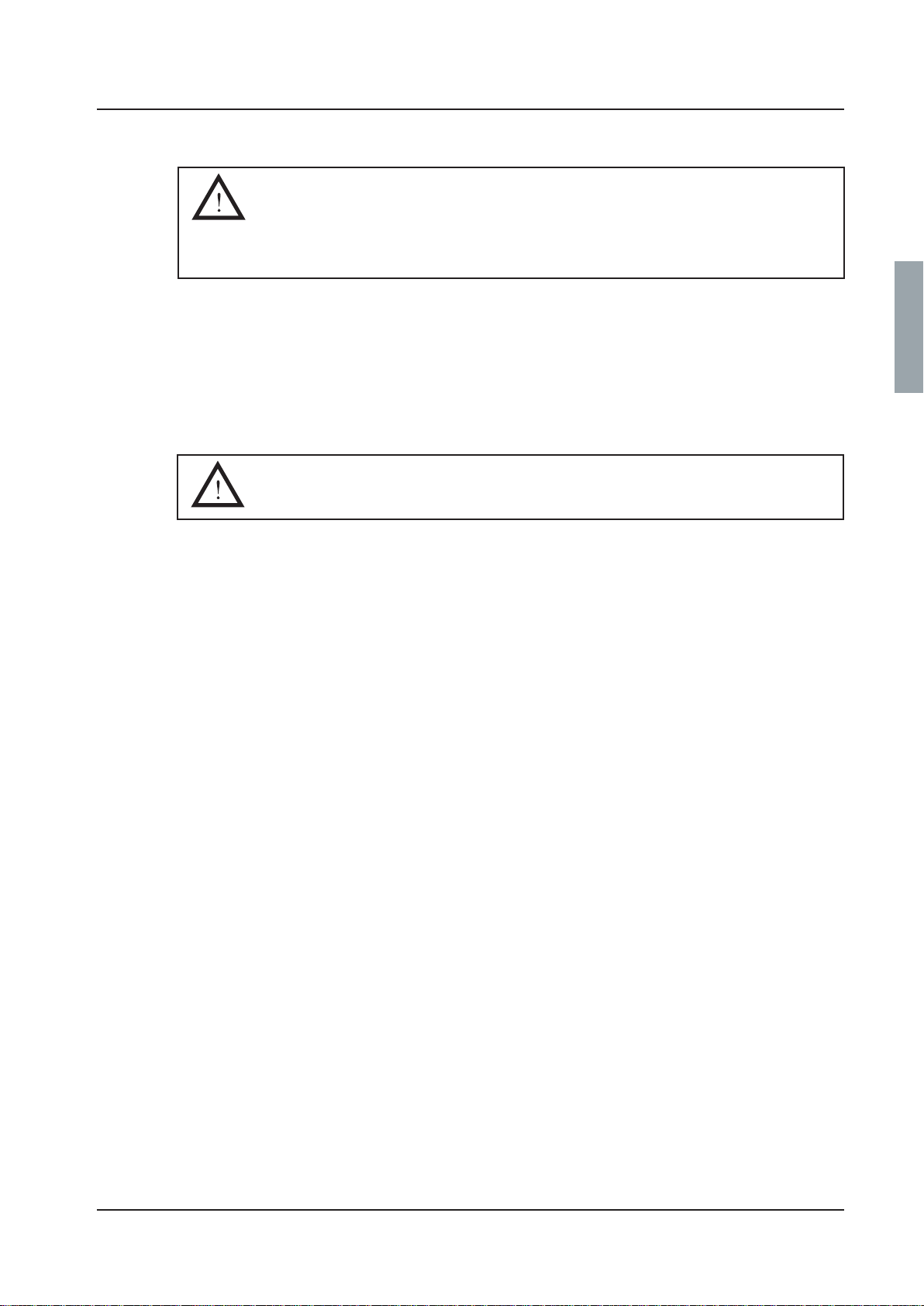
Fast-stepping a program
All safety functions are disabled for fast stepping.
Fast stepping must only be used during servicing.
Never stop fast stepping in a heating phase. If you do, the machine may
be damaged.
An ongoing program can be fast-stepped phase by phase. Fast stepping can be chosen during
an ongoing process.
1. Fast stepping is chosen in the service program; see tab 5 Software description and setting,
under DIP switches display (1.4.2.4).
2 . Set DS02 STEP in STATUS to 1 and press S . Exit the service program.
3. Fast-step with U.
4 . Reset DS02 STEP STATUS to 0 and press S . Exit the service program.
Reset DS02 STEP STATUS to 0 after completion of fast stepping.
Description
Service instructions
5019675-00Edition 0410


Software description and settings
Software description and settings
Contents
Description ________________________________________________ 3
Control panel ______________________________________________4
Display ________________________________________________ 4
Program selection buttons__________________________________ 4
Menu tree navigation buttons_______________________________ 5
Scroll in menus and lists _____________________________________5
Field editing _______________________________________________5
Password __________________________________________________ 6
Operator________________________________________________ 6
Parameter _______________________________________________ 6
Supervisor ______________________________________________6
Service _________________________________________________ 7
Programming ____________________________________________ 7
Menu tree __________________________________________ Appendix
Service instructions
5019675-00Edition 0410


Description
Software description and settings
This section describes the PACS 300 control and monitoring system. PACS 300 is an electronic
system that is used to control the various functions of the washer-disinfector. The letters
PACS stand for Programmable Autoclave Control System.
The purpose of the control system is to issue orders and send them to the executive
components of the washer-disinfector so that a number of process steps can be performed in
accordance with a predetermined template. The order signals are worked out by the computer
program of the control unit in conjunction with measurements of actual parameter values for the
current program. These are usually times, temperatures and pressures.
Several different pieces of equipment can be connected to the control unit for programming,
monitoring and documenting the disinfection processes.
The operator communicates with the control unit via a control panel or an ordinary PC.
All operator panels can be used to monitor the processes, since they display all the set
parameter values as well as actual values on request. All relevant data associated with a given
process, such as batch number, operator number, date, etc., can be entered by the operator.
Programs, system definitions and process data can be documented by connecting a printer to
the unit. A host computer can also be connected directly to the CPU of the control system.
When the need arises, a measuring and monitoring system entirely independent of the control
system can be set up by connecting a PACS SUPERVISOR system, consisting of CPU, operator
panel and connections to the control unit CPU. The measurements of the SUPERVISOR are
made by its own separate temperature and pressure sensors.
The computer contains programs for automatic calibration of the temperature and pressure
sensors. Where alternative correction constants are known, they can be entered manually. The
testing functions include means of activating analog and digital outputs and for monitoring
analog and digital inputs.
Service instructions
5019675-00Edition 0410
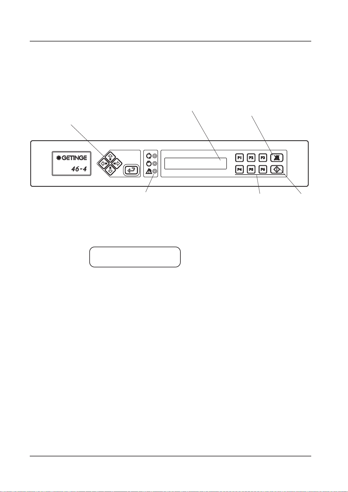
The control panel
The buttons on the control panel are used to choose programs, navigate the menu tree,
acknowledge error codes, etc.
Software description and settings
V1624
Display
Buttons for
menu tree
navigation
Display
P01 OP-SHORT-D
47.0 °C
Indicator lamps
The screen has two lines, each with a capacity of 20 characters.
Program selection buttons
P01 OP-SHORT-D
47.0 °C
Acknowledgement
of error
message
Start wash
program
Information or error messages appear on the bottom line and replace the text that would
otherwise appear here.
Program selection buttons
With 1-6 you can choose up to six programs. If the control system has more programs, the
subsequent ones are chosen from a scrollable list. You can reach the list of available programs
(from standby mode), by pressing S twice and choosing a program with J or H. Confirm
the chosen program with S .
5019675-00 Edition 0410
Service instructions

Software description and settings
Buttons for menu tree navigation
The are five buttons for navigating the panel. These fixed buttons are four arrow buttons that
control the cursor (I, K, J and H) and S.
I Used to go back one step (up one level) in menus. If the button is held down for a little
longer, you are returned to the main menu.
K Not used in menus and lists.
J Shows the next object in the list.
H Shows the previous object in the list.
S Goes to the chosen object in the list or opens a field for editing if there is an editable
field.
Scroll in menus and lists
You can use I, K, J and H to scroll through menus and lists. You can scroll either
line by line or two lines at a time, depending on what is displayed. The top line of the list may
look like the example below.
>PRINT LAST CYCLE
SYSTEM V
The angle bracket “>” to the left of the top line shows which object will be chosen if you press
S. Bottom right there is a “v” indicating that there are more objects in the list which are
displayed if you press J.
This is what you see if you are in a list. The “arrows” to the right show that there are objects
both above and below the displayed line.
When you reach the end of the object list, only one up-arrow appears at the right edge of the
display. Menus and lists are “endless”; you can reach the top of the list by pressing J at the
end of the list.
Field editing
S opens the chosen field for editing. The content of the field is changed with H or J.
These arrow keys scroll in an endless list containing numbers. When a field is opened for
editing, the first character is highlighted. To move the cursor use Ior K.
Entered values are saved when you press S. On saving, the system checks that the value is in
the permitted range.
>SYSTEM ^
ABOUT
SYSTEM ^
>ABOUT
Service instructions
5019675-00Edition 0410

Passwords
Software description and settings
There are five passwords with different levels of authorisation in the system program. The
operator password has the lowest authority; the programming password has full authority.
The password levels are as follows:
• Operator – code 558387.
• Parameter – contact service for code.
• Supervisor – contact service for code.
• Service – contact service for code.
• Programming – contact service for code.
NOTE: In the menu tree where the password must be entered there is a letter
code (between PW: A-K) which refers to the function for which the relevant
password is authorised.
When a password is entered, the top line shows “ENTER PASSWORD”. Press S to open the
entry field for editing . Each digit can be changed with J and H. I and K toggle
between the digits. Press S to confirm the entered password.
If the wrong password is entered, “WRONG PASSWORD” appears on the first line. Press S to
return to the display showing “ENTER PASSWORD”
Operator
Parameter
Supervisor
NOTE: The password cannot be changed.
Code in Authority to change
menu tree
A Parameters of type A and to see parameters of type I.
Code in Authority to change
menu tree
A Parameters of type A and to see parameters of type I.
H Process-critical configurations, parameters of type P.
Code in Authority to change
menu tree
A Parameters.
B Calendar (time and date)
H Process-critical configurations, parameters of type P.
J Password configuration
K Documentation
5019675-00 Edition 0410
Service instructions

Service
Programming
Software description and settings
Code in Authority to change
menu tree
A Parameters:
B Calendar (time and date)
C Sensor calibration
E Service messages
F. DIP switches
G Non-critical system configurations.
H Process-critical configurations, parameters of type P.
J Password configuration
K Documentation
Code in Authority to change
menu tree
A Parameters:
B Calendar (time and date)
C Sensor calibration
E Service messages
F DIP switches
G Non-critical system configurations.
H Process-critical configurations, parameters of type P.
I Programming (phases and programs)
J Password configuration
K Documentation
Service instructions
5019675-00Edition 0410

Software description and settings – Menu tree 1 (34)
Menu tree
General...............................................................................................................................................2
Main menu 1, Program name (1.1).....................................................................................................3
Select cycle (1.1.1)..........................................................................................................................3
Change parameters (1.1.2).............................................................................................................4
Main menu 2, Machine name (1.2).....................................................................................................4
Machine information (1.2) ...............................................................................................................4
Main menu 3, Cycle counter (1.3).......................................................................................................5
Variable list (1.3.1…).......................................................................................................................5
Main menu 4, Setup (1.4)...................................................................................................................6
Print selected cycles parameters (1.4.1).........................................................................................6
System display (1.4.2).....................................................................................................................6
Calendar display (1.4.2.1) ...........................................................................................................6
Time display (1.4.2.1.1) ...........................................................................................................7
Date display (1.4.2.1.2)............................................................................................................7
Calibration display (1.4.2.2).........................................................................................................8
Manual calibration display (1.4.2.2.1) ......................................................................................8
Automatic calibration display (1.4.2.2.2)..................................................................................8
Automatic calibration display (1.4.2.2.2)..................................................................................9
Calibrate selected sensor (1.4.2.2.2.1) ................................................................................9
Select sensor (1.4.2.2.2.2).................................................................................................10
Compensation table display (1.4.2.2.3) .................................................................................11
Configuration display (1.4.2.3)...................................................................................................11
Language display (1.4.2.3.1) .................................................................................................11
Date format display (1.4.2.3.2)...............................................................................................12
Pressure unit display (1.4.2.3.1.3).........................................................................................13
Temperature unit display (1.4.2.3.1.4)...................................................................................14
Printer display (1.4.2.3.2) ..........................................................................................................15
Printing mode display (1.4.2.3.2.1)........................................................................................15
Slow interval display (1.4.2.3.2.2)..........................................................................................16
Fast interval display (1.4.2.3.2.3)........................................................................................... 17
Printer baud rate display (1.4.2.3.2.4)....................................................................................18
Alarm clock display (1.4.2.3.3)...............................................................................................18
PACS address display (1.4.2.3.4)..........................................................................................19
Communication setup COM0 (1.4.2.3.5.1) ............................................................................20
Communication setup COM1 (1.4.2.3.5.2) ............................................................................21
Communication mode setup COM1 (1.4.2.3.5.3) ..................................................................22
DIP switches display (1.4.2.4)...................................................................................................23
Service display (1.4.2.5)............................................................................................................24
Error log display (1.4.2.5.1)....................................................................................................24
Service message display (1.4.2.5).........................................................................................25
Diagnostics display (1.4.2.5.3)...............................................................................................25
Test analogue input display (1.4.2.5.3.1)...........................................................................26
Test analogue output display (1.4.2.5.3.2).........................................................................27
Test digital input display (1.4.2.5.3.3).................................................................................28
Test digital output display (1.4.2.5.3.4) ..............................................................................29
Test user flag display (1.4.2.5.3.5).....................................................................................30
Test system flag display (1.4.2.5.3.6).................................................................................31
Test printer (1.4.2.5.3.7).....................................................................................................32
Test LED/buzzer display (1.4.2.5.3.8)................................................................................33
Save ram to flash display (1.4.2.6)............................................................................................34
About display (1.4.3).....................................................................................................................34
Utgåva 0402 Service instructions 5019675-00

Software description and settings – Menu tree 2 (34)
General
There are 4 main menus on the top level.
Main menu 1 (Program name) selects cycle and change parameters (1.1)
Main menu 2 (Machine name) shows information about machine name and the current
phase in the cycle. (1.2)
Main menu 3 (Cycle counter) shows a selectable variable. (1.3)
Main menu 4 (Setup) machine related setup. (1.4)
1
CYCLE COUNTER
00000
SETUP
P01 PROGRAM NAME
60.0C 0
GETINGE PACS 300
VERSION 3.5I (0283)
1.1 1.2 1.3 1.4
01 MACHINE NAME
02 PHASE NAME
SELECT PROGRAM CHANGE PARAMETERS
CALENDAR CONFIGURATION SERVICE
LANGUAGE DATE UNIT PRINTER ALARM CLOCK
LANGUAGE DATE FORMAT PRESSURE UNIT TEMP. UNIT
TEST ANALOG IN TEST ANALOG OUT TEST DIGITAL IN TEST DIGITAL OUT TEST USER FLAG TEST SYSTEM FLAG TEST PRINTER TEST LED/BUZZER
TIME HH:MM:SS DATE YYYY/MM/DD
1.1.1 1.1.2
ENTER
PASSWORD
PW: A, A+H
1.4.2.1 1.4.2.2 1.4.2.3 1.4.2.4
CALIBRATION DIP SWITCHES
PW: B PW: C PW: B,C,E,F PW: F PW: E PW: C,E,F
1.4.2.3.1 1.4.2.3.2 1.4.2.3.3
PRINTING MODE SLOW INTERNAL FAST INTERNAL
1.4.2.3.1.1
1.4.2.5.3.1 1.4.2.5.3.2 1.4.2.5.3.3 1.4.2.5.3.4 1.4.2.5.3.5 1.4.2.5.3.6 1.4.2.5.3.7 1.4.2.5.3.8
1.4.2.1.1 1.4.2.1.2
1.4.2.3.2.1 1.4.2.3.2.2 1.4.2.3.2.3 1.4.2.3.2.4
1.4.2.3.1.2 1.4.2.3.1.3 1.4.2.3.1.4
MANUAL CALIBRATION AUTO CALIBRATION COMPENSATION TABLE
PRINT LAST CYCLE SYSTEM ABOUT
1.4.2.2.1 1.4.2.2.2 1.4.2.2.3
1.4.1 1.4.2 1.4.3
ENTER
PASSWORD
1.4.2.5
PACS ADDRESS
CONTINUE 1 (32) Æ
1.4.2.2.2.1
1.4.2.3.4
COMMUNICATION
PRINTER BAUD RATE
SELECT SENSOR
1.4.2.3.5
1.4.2.2.2.2
1.4.2.6
SAVE TO RAM FLASH
ERROR LOG SERVICE MESSAGES DIAGNOSTICS
1.4.2.5.1 1.4.2.5.2 1.4.2.5.3
Utgåva 0402 Service instructions 5019675-00
-

Software description and settings – Menu tree 3 (34)
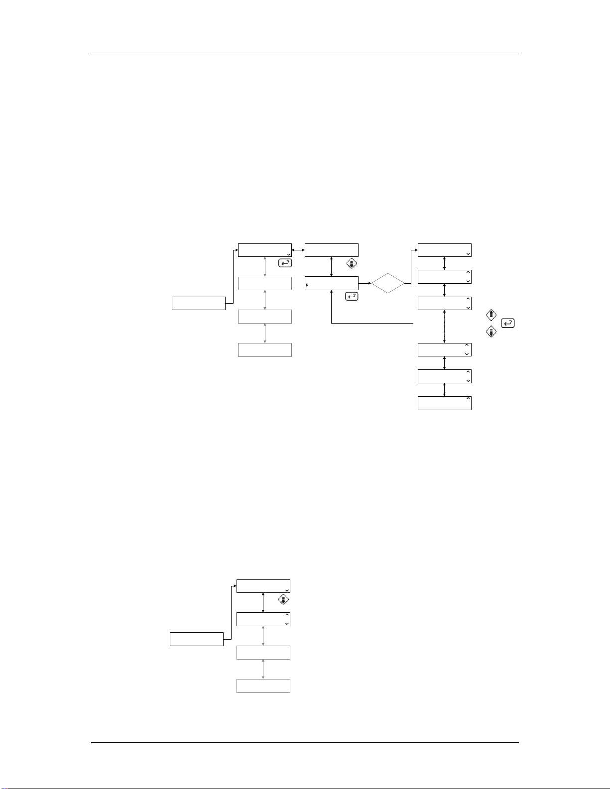
Main menu 1, Program name (1.1)
In standby mode, the display shows in top row the last selected cycle name
and in the second row two pre-selected variables, normally the temperature
in the washer and cycle counter. The main purpose of the menu is to select
a washing cycle and be able to change any changeable parameters.
There are two sub-menus in this section.
Select cycle. (1.1.1)
Change parameters. (1.1.2)
Select cycle (1.1.1)
In main menu 1 press enter to move to “SELECT PROGRAM” menu and
then press enter again to the cycle list menu. Use the up/down buttons to
mark the cycle and select the cycle by pressing the enter button. The
cycles are pre-configured in the program and cannot be changed by the
operator.
1.1.1.1
1.1.1.2
1.1.1.3
GETINGE PACS 300
VERSION 3.5I (0283)
P01 PROGRAM NAME
PARAM 1 PARAM 2
01 MACHINE NAME
02 PHASE NAME
1
CYCLE COUNTER
00000
1.1
1.2
1.3
SELECT PROGRAM
CHANGE PARAMETERS
SELECT PROGRAM
CHANGE PARAMETERS
1.1.1
1.1.2
01 PROGRAM #01
02 PROGRAM #02
02 PROGRAM #02
03 PROGRAM #03
03 PROGRAM #03
04 PROGRAM #04
SETUP
1.4
09 PROGRAM #09
10 PROGRAM #10
10 PROGRAM #10
11 PROGRAM #11
10 PROGRAM #10
11 PROGRAM #11
1.1.1.9
1.1.1.10
1.1.1.11
4FS030-01
Utgåva 0402 Service instructions 5019675-00
Software description and settings – Menu tree 4 (34)
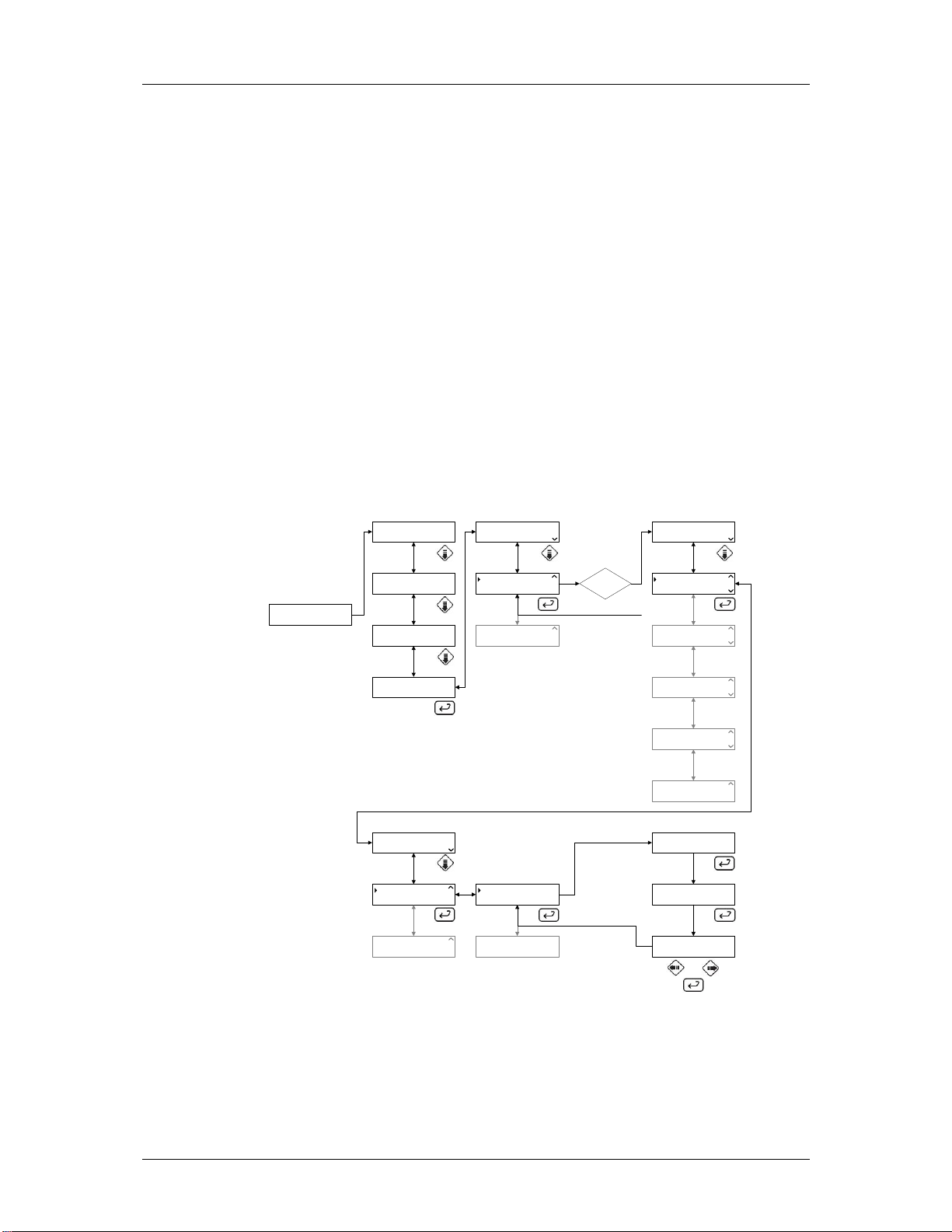
Change parameters (1.1.2)
In main menu 1 press enter to move to “SELECT PROGRAM” menu then
press down button to activate “CHANGE PARAMETERS” Press enter
again to select.
Each cycle has a set of parameters that are pre-configured. When a cycle
has been selected, explained in the previous section, the parameters will
be showed in the display. The number of parameters displayed depends on
the how the cycle was configured when it was created in the program.
The parameters that have an “A” indication on the right lower side are
adjustable. By pressing enter button the value can be changed with
password level A. If the indication is an “I” the parameter is only
P01 PROGRAM NAME
PARAM 1 PARAM 2
01 MACHINE NAME
02 PHASE NAME
GETINGE PACS 300
VERSION 3.5I (0283)
1
CYCLE COUNTER
00000
SETUP
information. P parameters can be changed if password level A+H.
Main menu 2, Machine name (1.2)
Main menu 2 shows information about machine and the current phase. The
information is not changeable.
1.1
1.2
1.3
1.4
SELECT PROGRAM
CHANGE PARAMETERS
SELECT PROGRAM
CHANGE PARAMETERS
1.1.1
1.1.2
ENTER
PASSWORD
PW: A, A+H
WASH DOS TEMP
035.0C A
PARAMETER #02
PARAMETER #03
RETURN
PARAMETER #57
PARAMETER #58
PARAMETER #59
1.1.2.1
1.1.2.2
1.1.2.3
1.1.2.57
1.1.2.58
1.1.2.59
4FS031-01
Machine information (1.2)
The top row displays the disinfections name/ID and the lower row shows
the current phase.
P01 PROGRAM NAME
PARAM 1 PARAM 2
01 MACHINE NAME
02 PHASE NAME
GETINGE PACS 300
VERSION 3.5I (0283)
Utgåva 0402 Service instructions 5019675-00
1
CYCLE COUNTER
00000
SETUP
1.1
1.2
1.3
1.4
4FS032-01

Software description and settings – Menu tree 5 (34)
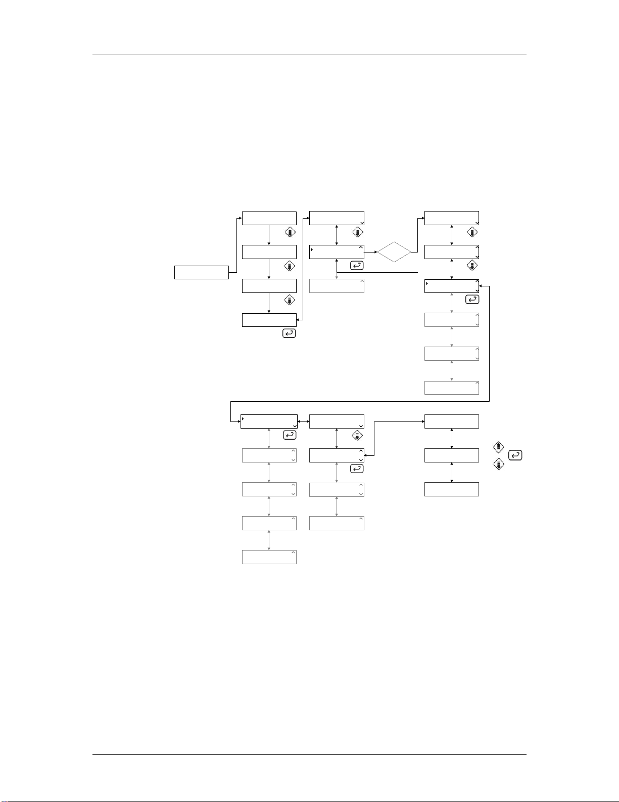
Main menu 3, Cycle counter (1.3)
In this menu a selectable variable can be displayed. The top row displays
the variable name and the lower row displays the value.
Variable list (1.3.1…)
There are a configured number of variables available for each cycle. This
list is for information only. To select a variable to display scroll down/up and
then press enter to select the variable.
GETINGE PACS 300
VERSION 3.5I (0283)
P01 PROGRAM NAME
PARAM 1 PARAM 2
01 MACHINE NAME
02 PHASE NAME
1
CYCLE COUNTER
00000
1.1
1.2
1.3
CYCLE COUNTER
00000
VARIABLE 02
VALUE #02
VARIABLE 03
VALUE #03
1.3.1
1.3.2
1.3.3
1.3.42
1.3.43
1.3.44
SETUP
1.4
VARIABLE 42
VALUE #42
VARIABLE 43
VALUE #43
NO VARIABLE 44
>
4FS033-01
Utgåva 0402 Service instructions 5019675-00

Software description and settings – Menu tree 6 (34)
Main menu 4, Setup (1.4)
Main menu 4 is the machine set-up menu. The set-up menu has 3 submenus.
Print last selected cycle parameters. (1.4.1)
System configuration menus. (1.4.2)
About the system. (1.4.3)
Print selected cycles parameters (1.4.1)
When a cycle is selected, in main menu 1, the cycle’s parameters can be
printed to the printer.
Press down the button three times to get to the set-up menu, then press the
enter button to select set-up. By pressing enter one more time the
confirmation screen for printout opens. Use the left/right buttons to select
“YES” or “NO” to start printing or exit without printing the parameters for the
selected cycle.
GETINGE PACS 300
VERSION 3.5I (0283)
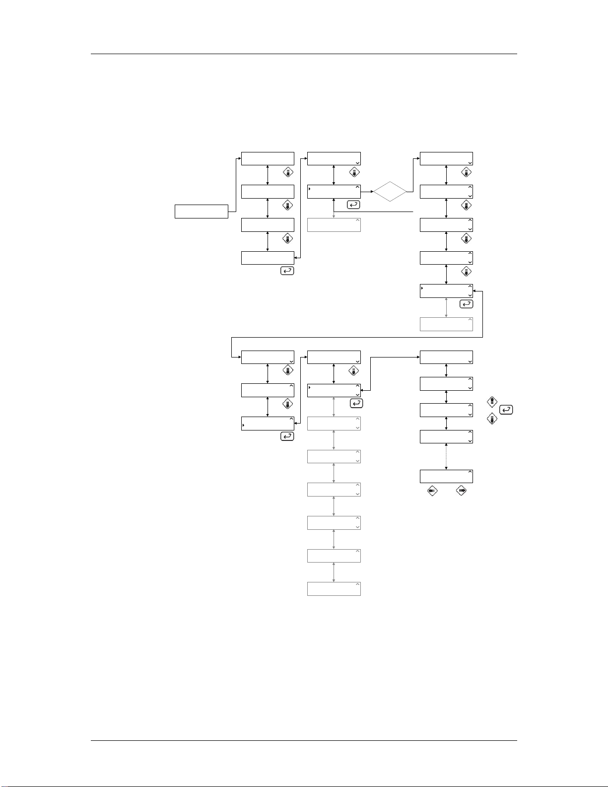
System display (1.4.2)
In the system configuration menu there are six sub-menus.
Calendar where time and date can be entered. (1.4.2.1)
Calibration of analogy input values. (1.4.2.2)
Configuration to set units, printer, alarm clocks and node address.
(1.4.2.3)
DIP switches. (1.4.2.4)
Service menu with error log, service message and diagnostics. (1.4.2.5)
P01 PROGRAM NAME
PARAM 1 PARAM 2
01 MACHINE NAME
02 PHASE NAME
1
CYCLE COUNTER
00000
SETUP
1.1
1.2
1.3
1.4
PRINT LAST CYCLE
SYSTEM
SYSTEM
ABOUT
SYSTEM
ABOUT
1.4.1
1.4.2
1.4.3
PRINT LAST CYCLE
YES NO
4FS034-01
1.4.1.1
Save ram to flash. (1.4.2.6)
Calendar display (1.4.2.1)
The time and date can be set in this menu. There is one sub-menu for each
function.
Set time. (1.4.2.1.1)
Set date. (1.4.2.1.2)
Utgåva 0402 Service instructions 5019675-00

Software description and settings – Menu tree 7 (34)
Time display (1.4.2.1.1)
To set the time follow the path in the figure, enter the password and press
enter when calendar menu is selected. To edit the time press the enter
button. Change the time by pressing the up/down buttons for the value and
using the left/right buttons to select the different fields. When the time is
GETINGE PACS 300
VERSION 3.5I (0283)
correct press the enter button to confirm the change.
Date display (1.4.2.1.2)
To set the date follow the path in the figure, enter the password and press
enter when calendar menu is selected. To edit the date press the enter
button. Change the date by pressing the up/down buttons for the value and
using the left/right buttons to select the different fields. When the date is
P01 PROGRAM NAME
PARAM 1 PARAM 2
01 MACHINE NAME
02 PHASE NAME
1
CYCLE COUNTER
00000
SETUP
1.1
1.2
1.3
1.4
PRINT LAST CYCLE
SYSTEM
SYSTEM
ABOUT
SYSTEM
ABOUT
1.4.1
1.4.2
1.4.3
ENTER
PASSWORD
PW: B
CALENDAR
CALIBRATION
CALIBRATION
CONFIGURATION
RETURN
CONFIGURATION
DIP SWITCHES
DIP SWITCHES
SERVICE
SERVICE
SAVE TO RAM FLASH
SERVICE
SAVE TO RAM FLASH
1.4.2.1
1.4.2.2
1.4.2.3
1.4.2.4
1.4.2.5
1.4.2.6
TIME HH:MM:SS
15:45:50
DATE YYYY/MM/DD
2003-05-19
4FS035-01
1.4.2.1.1
1.4.2.1.2
GETINGE PACS 300
VERSION 3.5I (0283)
P01 PROGRAM NAME
PARAM 1 PARAM 2
01 MACHINE NAME
02 PHASE NAME
1
CYCLE COUNTER
00000
SETUP
1.1
1.2
1.3
1.4
PRINT LAST CYCLE
SYSTEM
SYSTEM
ABOUT
SYSTEM
ABOUT
1.4.1
1.4.2
1.4.3
ENTER
PASSWORD
PW: B
CALENDAR
CALIBRATION
CALIBRATION
CONFIGURATION
RETURN
CONFIGURATION
DIP SWITCHES
DIP SWITCHES
SERVICE
SERVICE
SAVE TO RAM FLASH
SERVICE
SAVE TO RAM FLASH
1.4.2.1
1.4.2.2
1.4.2.3
1.4.2.4
1.4.2.5
1.4.2.6
correct press the enter button to confirm the change.
Utgåva 0402 Service instructions 5019675-00
TIME HH:MM:SS
15:45:50
DATE YYYY/MM/DD
2003-05-19
1.4.2.1.1
1.4.2.1.2
4FS036-01

Software description and settings – Menu tree 8 (34)
Calibration display (1.4.2.2)
Calibration menu is used to calibrate analogy input values. There are three
sub-menus in the calibration.
Manual calibration. (1.4.2.2.1)
Automatic calibration. (1.4.2.2.2)
Adjust the compensation table. N/A. (1.4.2.2.3)
Manual calibration display (1.4.2.2.1)
In manual calibration the two (2) values for offset and span can be
manually entered. To get to the manual calibrations follow the path in the
figure below. Change the value by pressing the up/down buttons and using
the left/right buttons to select the different fields. When the value is correct
press the enter button to confirm the changes.
P01 PROGRAM NAME
PARAM 1 PARAM 2
1.1
PRINT LAST CYCLE
SYSTEM
1.4.1
CALENDAR
CALIBRATION
1.4.2.1
GETINGE PACS 300
VERSION 3.5I (0283)
01 MACHINE NAME
02 PHASE NAME
1
CYCLE COUNTER
00000
SETUP
MANUAL CALIBRATION
AUTO CALIBRATION
AUTO CALIBRATION
COMPENSATION TABLE
AUTO CALIBRATION
COMPENSATION TABLE
1.4.2.2.1
1.4.2.2.2
1.4.2.2.3
1.2
SYSTEM
ABOUT
1.3
> SYSTEM
ABOUT
1.4
1.4.3
1.4.2
ENTER
PASSWORD
PW: C
CALIBRATION
CONFIGURATION
RETURN
CONFIGURATION
DIP SWITCHES
DIP SWITCHES
SERVICE
SERVICE
SAVE TO RAM FLASH
SERVICE
SAVE TO RAM FLASH
00 CALIBRATION TYPE
OFFSET SPAN
01 CALIBRATION TYPE
OFFSET SPAN
02 CALIBRATION TYPE
OFFSET SPAN
31 CALIBRATION TYPE
OFFSET SPAN
1.4.2.2
1.4.2.3
1.4.2.4
1.4.2.5
1.4.2.6
1.4.2.2.1.1
1.4.2.2.1.2
1.4.2.2.1.3
1.4.2.2.1.32
Utgåva 0402 Service instructions 5019675-00
4FS037-01
Software description and settings – Menu tree 9 (34)
Automatic calibration display (1.4.2.2.2)
This menu has two sub-menus.
Continue. (1.4.2.2.2.1)
Select sensor. (1.4.2.2.2.2)
In automatic calibration a sensor has to be selected for calibration. This is
done in the select sensor menu. When a sensor(s) is/are selected for
calibration the continue menu indicates the number of sensors selected and
an arrow appears in the right side of the display. When leaving the
calibration menu all selected sensors are disabled.
Calibrate selected sensor (1.4.2.2.2.1)
When one or more similar sensor(s) is/are selected (see 1.4.2.2.2.2) is this
indicated with an arrow at the right side of the display beside the continue
word on the first row. By pressing enter lo reference value is displayed.
When the value is stabile the value is entered and confirmed by pressing
enter. Now the high reference display appears and when this value is
stable the value is entered followed by the enter button. It is now possible
to print the calibration value by setting the cursor at “YES” and pressing the
enter button or “NO” to reject the printing.
P01 PROGRAM NAME
PARAM 1 PARAM 2
1.1
PRINT LAST CYCLE
SYSTEM
1.4.1
CALENDAR
CALIBRATION
1.4.2.1
GETINGE PACS 300
VERSION 3.5I (0283)
01 MACHINE NAME
02 PHASE NAME
1
CYCLE COUNTER
00000
SETUP
MANUAL CALIBRATION
AUTO CALIBRATION
AUTO CALIBRATION
COMPENSATION TABLE
AUTO CALIBRATION
COMPENSATION TABLE
1.4.2.2.1
1.4.2.2.2
1.4.2.2.3
1.2
1.3
1.4
SYSTEM
ABOUT
SYSTEM
ABOUT
CONTINUE 1 (32) Æ
SELECT SENSOR
CONTINUE 1 (32) Æ
SELECT SENSOR
1.4.2.2.2.1
1.4.2.2.2.2
1.4.2
1.4.3
ENTER
PASSWORD
PW: C
CALIBRATION
CONFIGURATION
RETURN
CONFIGURATION
DIP SWITCHES
DIP SWITCHES
SERVICE
SERVICE
SAVE TO RAM FLASH
SERVICE
SAVE TO RAM FLASH
LOW REF
VALUE %
HIGH REF
VALUE %
PRINT CALIBRATION
YES NO
1.4.2.2
1.4.2.3
1.4.2.4
1.4.2.5
1.4.2.6
1.4.2.2.2.1.1
1.4.2.2.2.1.2
1.4.2.2.2.1.3
Utgåva 0402 Service instructions 5019675-00
4FS038-01

Software description and settings – Menu tree 10 (34)
Select sensor (1.4.2.2.2.2)
Press the enter button on the sensor list to select for automatic calibration.
Then press confirm by setting the cursor on “YES” and press enter again.
The sensor is now selected. Note that several sensors can be selected at
the same time. If more then one sensor is selected they have to be of
similar type.
P01 PROGRAM NAME
PARAM 1 PARAM 2
1.1
PRINT LAST CYCLE
SYSTEM
1.4.1
CALENDAR
CALIBRATION
1.4.2.1
GETINGE PACS 300
VERSION 3.5I (0283)
01 MACHINE NAME
02 PHASE NAME
1
CYCLE COUNTER
00000
SETUP
MANUAL CALIBRATION
AUTO CALIBRATION
AUTO CALIBRATION
COMPENSATION TABLE
AUTO CALIBRATION
COMPENSATION TABLE
1.4.2.2.1
1.4.2.2.2
1.4.2.2.3
1.2
1.3
1.4
SYSTEM
ABOUT
SYSTEM
ABOUT
CONTINUE 1 (32) Æ
SELECT SENSOR
CONTINUE 1 (32) Æ
SELECT SENSOR
1.4.2.2.2.1
1.4.2.2.2.2
1.4.2
1.4.3
ENTER
PASSWORD
PW: C
CALIBRATION
CONFIGURATION
RETURN
CONFIGURATION
DIP SWITCHES
DIP SWITCHES
SERVICE
SERVICE
SAVE TO RAM FLASH
SERVICE
SAVE TO RAM FLASH
00 CALIBRATION TYPE
VALUE % CAL NO
01 CALIBRATION TYPE
VALUE % CAL NO
02 CALIBRATION TYPE
VALUE % CAL NO
1.4.2.2.2.2.32
31 CALIBRATION TYPE
VALUE % CAL NO
1.4.2.2
1.4.2.3
1.4.2.4
1.4.2.5
1.4.2.6
1.4.2.2.2.2.1
1.4.2.2.2.2.2
1.4.2.2.2.2.3
Utgåva 0402 Service instructions 5019675-00
4FS039-01

Software description and settings – Menu tree 11 (34)
Compensation table display (1.4.2.2.3)
This menu is not applicable on this machine.
Configuration display (1.4.2.3)
The configuration display is used to set the language, unit format. Also the
printer is configured. Alarm clock setting and finally the PACS address.
There are four sub-menus.
Language. (1.4.2.3.1)
Date format. (1.4.2.3.2)
Pressure units. (1.4.2.3.3)
Temperature units. (1.4.2.3.4)
Language display (1.4.2.3.1)
The language for the different displays is set in this display. To select the
different languages press enter and select the appropriate language.
Confirm the selection by pressing the enter button.
GETINGE PACS 300
VERSION 3.5I (0283)
P01 PROGRAM NAME
PARAM 1 PARAM 2
01 MACHINE NAME
02 PHASE NAME
1
CYCLE COUNTER
00000
SETUP
LANGUAGE DATE FORMAT
PRINTER
PRINTER
ALARM CLOCK
ALARM CLOCK
PACS ADDRESS
1.4.2.3.1
1.4.2.3.2
1.4.2.3.3
1.1
1.2
1.3
1.4
PRINT LAST CYCLE
SYSTEM
SYSTEM
ABOUT
SYSTEM
ABOUT
LANGUAGE
ENGLISH
DATE FORMAT
DD/MM/YYYY
PRESSURE UNIT
KPA
1.4.1
1.4.2
1.4.3
1.4.2.3.1.1
1.4.2.3.1.2
1.4.2.3.1.3
ENTER
PASSWORD
PW: B,C,E,F
CALENDAR
CALIBRATION
CALIBRATION
CONFIGURATION
RETURN
CONFIGURATION
DIP SWITCHES
DIP SWITCHES
SERVICE
SERVICE
SAVE TO RAM FLASH
SERVICE
SAVE TO RAM FLASH
1.4.2.1
1.4.2.2
1.4.2.3
1.4.2.4
1.4.2.5
1.4.2.6
PACS ADDRESS
COMMUNICATION
PACS ADDRESS
COMMUNICATION
1.4.2.3.4
1.4.2.3.5
TEMP UNIT
C
1.4.2.3.1.4
4FS041-01
Utgåva 0402 Service instructions 5019675-00
Software description and settings – Menu tree 12 (34)
Date format display (1.4.2.3.2)
The date format is selected from a list in this display. There are three
different formats. To change the unit press the enter button to display the
different format and select the appropriate format. Confirm the selection by
pressing the enter button.
YYYY/MM/DD. (1.4.2.3.2.1)
MM/DD/YYYY. (1.4.2.3.2.2)
DD/MM/YYYY. (1.4.2.3.2.3)
GETINGE PACS 300
VERSION 3.5I (0283)
P01 PROGRAM NAME
PARAM 1 PARAM 2
01 MACHINE NAME
02 PHASE NAME
1
CYCLE COUNTER
00000
SETUP
LANGUAGE DATE FORMAT
PRINTER
PRINTER
ALARM CLOCK
ALARM CLOCK
PACS ADDRESS
1.4.2.3.1
1.4.2.3.2
1.4.2.3.3
1.1
1.2
1.3
1.4
PRINT LAST CYCLE
SYSTEM
SYSTEM
ABOUT
SYSTEM
ABOUT
LANGUAGE
ENGLISH
DATE FORMAT
DD/MM/YYYY
PRESSURE UNIT
KPA
1.4.1
1.4.2
1.4.3
1.4.2.3.1.1
1.4.2.3.1.2
1.4.2.3.1.3
ENTER
PASSWORD
PW: B,C,E,F
CALENDAR
CALIBRATION
CALIBRATION
CONFIGURATION
RETURN
CONFIGURATION
DIP SWITCHES
DIP SWITCHES
SERVICE
SERVICE
SAVE TO RAM FLASH
SERVICE
SAVE TO RAM FLASH
DATE FORMAT
YYYY/MM/DD 1(3)
DATE FORMAT
MM/DD/YYYY 2(3)
DATE FORMAT
DD/MM/YYYY 3(3)
1.4.2.3.1.2.1
1.4.2.3.1.2.2
1.4.2.3.1.2.3
1.4.2.1
1.4.2.2
1.4.2.3
1.4.2.4
1.4.2.5
1.4.2.6
PACS ADDRESS
COMMUNICATION
PACS ADDRESS
COMMUNICATION
1.4.2.3.4
1.4.2.3.5
TEMP UNIT
C
1.4.2.3.1.4
Utgåva 0402 Service instructions 5019675-00
4FS042-01

Software description and settings – Menu tree 13 (34)
Pressure unit display (1.4.2.3.1.3)
Three different pressure units are available. To change the unit press enter
to display the different units and select the appropriate unit. Confirm the
selection by pressing the enter button. Note. This is only to display the
appropriate units, the value will not be recalculated.
BAR. (1.4.2.3.1.3.1)
KPA. (1.4.2.3.1.3.2)
PSI. (1.4.2.3.1.3.3)
GETINGE PACS 300
VERSION 3.5I (0283)
P01 PROGRAM NAME
PARAM 1 PARAM 2
01 MACHINE NAME
02 PHASE NAME
1
START-INFO
00:00:00
SETUP
LANGUAGE DATE FORMAT
PRINTER
PRINTER
ALARM CLOCK
ALARM CLOCK
PACS ADDRESS
PACS ADDRESS
COMMUNICATION
1.4.2.3.1
1.4.2.3.2
1.4.2.3.3
1.4.2.3.4
1.1
1.2
1.3
1.4
PRINT LAST CYCLE
SYSTEM
SYSTEM
ABOUT
SYSTEM
ABOUT
LANGUAGE
ENGLISH
DATE FORMAT
DD/MM/YYYY
PRESSURE UNIT
KPA
TEMP UNIT
C
1.4.1
1.4.2
1.4.3
1.4.2.3.1.1
1.4.2.3.1.2
1.4.2.3.1.3
1.4.2.3.1.4
ENTER
PASSWORD
PW: B,C,E,F
CALENDAR
CALIBRATION
CALIBRATION
CONFIGURATION
RETURN
CONFIGURATION
DIP SWITCHES
DIP SWITCHES
SERVICE
SERVICE
SAVE TO RAM FLASH
SERVICE
SAVE TO RAM FLASH
PRESSURE UNIT
BAR 1(3)
PRESSURE UNIT
KPA 2(3)
PRESSURE UNIT
PSI 3(3)
1.4.2.3.1.3.1
1.4.2.3.1.3.2
1.4.2.3.1.3.3
1.4.2.1
1.4.2.2
1.4.2.3
1.4.2.4
1.4.2.5
1.4.2.6
PACS ADDRESS
COMMUNICATION
1.4.2.3.5
Utgåva 0402 Service instructions 5019675-00
4FS043-01

Software description and settings – Menu tree 14 (34)
Temperature unit display (1.4.2.3.1.4)
Two different units can be displayed. To change the unit press enter to
display the different units and select the appropriate unit. Confirm the
selection by pressing enter. Note. This is only to display the appropriate
units, the value will not be recalculated
Celsius. (1.4.2.3.1.4.1)
Fahrenheit. (1.4.2.3.1.4.2)
GETINGE PACS 300
VERSION 3.5I (0283)
P01 PROGRAM NAME
PARAM 1 PARAM 2
01 MACHINE NAME
02 PHASE NAME
1
CYCLE COUNTER
00000
SETUP
LANGUAGE DATE FORMAT
PRINTER
PRINTER
ALARM CLOCK
ALARM CLOCK
PACS ADDRESS
1.4.2.3.1
1.4.2.3.2
1.4.2.3.3
1.1
1.2
1.3
1.4
PRINT LAST CYCLE
SYSTEM
SYSTEM
ABOUT
SYSTEM
ABOUT
LANGUAGE
ENGLISH
DATE FORMAT
DD/MM/YYYY
PRESSURE UNIT
KPA
1.4.1
1.4.2
1.4.3
1.4.2.3.1.1
1.4.2.3.1.2
1.4.2.3.1.3
ENTER
PASSWORD
PW: B,C,E,F
CALENDAR
CALIBRATION
CALIBRATION
CONFIGURATION
RETURN
CONFIGURATION
DIP SWITCHES
DIP SWITCHES
SERVICE
SERVICE
SAVE TO RAM FLASH
SERVICE
SAVE TO RAM FLASH
TEMP UNIT
C 1(2)
1.4.2.3.1.4.1
1.4.2.1
1.4.2.2
1.4.2.3
1.4.2.4
1.4.2.5
1.4.2.6
PACS ADDRESS
COMMUNICATION
PACS ADDRESS
COMMUNICATION
1.4.2.3.4
1.4.2.3.5
TEMP UNIT
C
1.4.2.3.1.4
TEMP UNIT
F 2(2)
1.4.2.3.1.4.2
Utgåva 0402 Service instructions 5019675-00
4FS044-01

Software description and settings – Menu tree 15 (34)
Printer display (1.4.2.3.2)
All settings for printer and logging are made in this section. There are 4
sub-menus:
Printer mode N/A. (1.4.2.3.2.1)
Slow interval. (1.4.2.3.2.2)
Fast interval. (1.4.2.3.2.3)
Baud rate for printer. (1.4.2.3.2.4)
Printing mode display (1.4.2.3.2.1)
This menu only have mode 1. Only process values printed.
GETINGE PACS 300
VERSION 3.5I (0283)
P01 PROGRAM NAME
PARAM1 PARAM 2
01 MACHINE NAME
02 PHASE NAME
1
CYCLE COUNTER
00000
SETUP
LANGUAGE DATE FORMA T
PRINTER
PRINTER
ALARM CLOCK
ALARM CLOCK
PACS ADDRESS
1.4.2.3.1
1.4.2.3.2
1.4.2.3.3
1.1
1.2
1.3
1.4
PRINT LAST CYCLE
SYSTEM
SYSTEM
ABOUT
SYSTEM
ABOUT
PRINTING MODE
4
SLOW INTERVAL
01:00
FAST INTERVAL
20:00
1.4.1
1.4.2
1.4.3
1.4.2.3.2.1
1.4.2.3.2.2
1.4.2.3.2.3
ENTER
PASSWORD
PW: B,C,E,F
CALENDAR
CALIBRATION
CALIBRATION
CONFIGURATION
RETURN
CONFIGURATION
DIP SWITCHES
DIP SWITCHES
SERVICE
SERVICE
SAVE TO RAM FLASH
SERVICE
SAVE TO RAM FLASH
1.4.2.1
1.4.2.2
1.4.2.3
1.4.2.4
1.4.2.5
1.4.2.6
PACS ADDRESS
COMMUNICATION
PACS ADDRESS
COMMUNICATION
1.4.2.3.4
1.4.2.3.5
PRINTER BAUD RATE
2400
1.4.2.3.2.4
4FS045-01
Utgåva 0402 Service instructions 5019675-00

Software description and settings – Menu tree 16 (34)
Slow interval display (1.4.2.3.2.2)
This is the slow interval-logging time rate. Which phases are using this time
rate is pre-configured in the program for each phase.
P01 PROGRAM NAME
PARAM 1 PARAM 2
1.1
PRINT LAST CYCLE
SYSTEM
1.4.1
CALENDAR
CALIBRATION
1.4.2.1
GETINGE PACS 300
VERSION 3.5I (0283)
01 MACHINE NAME
02 PHASE NAME
1
CYCLE COUNTER
00000
SETUP
LANGUAGE DATE FORMA T
PRINTER
PRINTER
ALARM CLOCK
ALARM CLOCK
PACS ADDRESS
PACS ADDRESS
COMMUNICATION
1.4.2.3.1
1.4.2.3.2
1.4.2.3.3
1.4.2.3.4
1.2
1.3
1.4
SYSTEM
ABOUT
SYSTEM
ABOUT
PRINTING MODE
4
SLOW INTERVAL
20:00
FAST INTERVAL
01:00
PRINTER BAUD RATE
2400
1.4.2
1.4.3
1.4.2.3.2.1
1.4.2.3.2.2
1.4.2.3.2.3
1.4.2.3.2.4
ENTER
PASSWORD
PW: B,C,E,F
CALIBRATION
CONFIGURATION
RETURN
CONFIGURATION
DIP SWITCHES
DIP SWITCHES
SERVICE
SERVICE
SAVE TO RAM FLASH
SERVICE
SAVE TO RAM FLASH
1.4.2.2
1.4.2.3
1.4.2.4
1.4.2.5
1.4.2.6
PACS ADDRESS
COMMUNICATION
1.4.2.3.5
4FS046-01
Utgåva 0402 Service instructions 5019675-00

Software description and settings – Menu tree 17 (34)
Fast interval display (1.4.2.3.2.3)
This is the fast interval-logging time rate. Which phases are using this time
rate is pre-configured in the program for each phase.
P01 PROGRAM NAME
PARAM 1 PARAM 2
1.1
PRINT LAST CYCLE
SYSTEM
1.4.1
CALENDAR
CALIBRATION
1.4.2.1
GETINGE PACS 300
VERSION 3.5I (0283)
01 MACHINE NAME
02 PHASE NAME
1
CYCLE COUNTER
00000
SETUP
LANGUAGE DATE FORMAT
PRINTER
PRINTER
ALARM CLOCK
ALARM CLOCK
PACS ADDRESS
PACS ADDRESS
COMMUNICATION
1.4.2.3.1
1.4.2.3.2
1.4.2.3.3
1.4.2.3.4
1.2
1.3
1.4
SYSTEM
ABOUT
SYSTEM
ABOUT
PRINTING MODE
4
SLOW INTERVAL
20:00
FAST INTERVAL
01:00
PRINTER BAUD RATE
2400
1.4.2
1.4.3
1.4.2.3.2.1
1.4.2.3.2.2
1.4.2.3.2.3
1.4.2.3.2.4
ENTER
PASSWORD
PW: B,C,E,F
CALIBRATION
CONFIGURATION
RETURN
CONFIGURATION
DIP SWITCHES
DIP SWITCHES
SERVICE
SERVICE
SAVE TO RAM FLASH
SERVICE
SAVE TO RAM FLASH
1.4.2.2
1.4.2.3
1.4.2.4
1.4.2.5
1.4.2.6
PACS ADDRESS
COMMUNICATION
1.4.2.3.5
Figur 1 4FS047-01
Utgåva 0402 Service instructions 5019675-00

Software description and settings – Menu tree 18 (34)
Printer baud rate display (1.4.2.3.2.4)
The baud rate for the printer is selected in this menu. There are seven
different baud rates.
1200. (1.4.2.3.2.4.1)
2400. (1.4.2.3.2.4.2)
4800. (1.4.2.3.2.4.3)
9600. (1.4.2.3.2.4.4)
19200. (1.4.2.3.2.4.5)
38400. (1.4.2.3.2.4.6)
57600. (1.4.2.3.2.4.7)
P01 PROGRAM NAME
PARAM 1 PARAM 2
1.1
PRINT LAST CYCLE
SYSTEM
1.4.1
CALENDAR
CALIBRATION
1.4.2.1
GETINGE PACS 300
VERSION 3.5I (0283)
01 MACHINE NAME
02 PHASE NAME
1
CYCLE COUNTER
00000
SETUP
LANGUAGE DATE FORMAT
PRINTER
PRINTER
ALARM CLOCK
ALARM CLOCK
PACS ADDRESS
PACS ADDRESS
COMMUNICATION
PACS ADDRESS
COMMUNICATION
1.4.2.3.1
1.4.2.3.2
1.4.2.3.3
1.4.2.3.4
1.4.2.3.5
1.2
1.3
1.4
SYSTEM
ABOUT
SYSTEM
ABOUT
PRINTING MODE
4
SLOW INTERVAL
20:00
FAST INTERVAL
01:00
PRINTER BAUD RATE
2400
1.4.2
1.4.3
1.4.2.3.2.1
1.4.2.3.2.2
1.4.2.3.2.3
1.4.2.3.2.4
ENTER
PASSWORD
PW: B,C,E,F
CALIBRATION
CONFIGURATION
RETURN
CONFIGURATION
DIP SWITCHES
DIP SWITCHES
SERVICE
SERVICE
SAVE TO RAM FLASH
SERVICE
SAVE TO RAM FLASH
PRINTER BAUD RATE
1200
PRINTER BAUD RATE
2400
PRINTER BAUD RATE
4800
PRINTER BAUD RATE
9600
PRINTER BAUD RATE
19200
PRINTER BAUD RATE
38400
PRINTER BAUD RATE
57600
1.4.2.2
1.4.2.3
1.4.2.4
1.4.2.5
1.4.2.6
1.4.2.3.2.4.1
1.4.2.3.2.4.2
1.4.2.3.2.4.3
1.4.2.3.2.4.4
1.4.2.3.2.4.5
1.4.2.3.2.4.6
1.4.2.3.2.4.7
Alarm clock display (1.4.2.3.3)
This is not applicable on this machine.
Utgåva 0402 Service instructions 5019675-00
4FS048-01

Software description and settings – Menu tree 19 (34)
PACS address display (1.4.2.3.4)
The node address for the PACS is entered in this display.
P01 PROGRAM NAME
PARAM 1 PARAM 2
1.1
PRINT LAST CYCLE
SYSTEM
1.4.1
CALENDAR
CALIBRATION
1.4.2.1
GETINGE PACS 300
VERSION 3.5I (0283)
01 MACHINE NAME
02 PHASE NAME
1
CYCLE COUNTER
00000
SETUP
LANGUAGE DATE FORMAT
PRINTER
PRINTER
ALARM CLOCK
ALARM CLOCK
PACS ADDRESS
PACS ADDRESS
COMMUNICATION
1.4.2.3.1
1.4.2.3.2
1.4.2.3.3
1.4.2.3.4
1.2
SYSTEM
ABOUT
1.3
SYSTEM
ABOUT
1.4
1.4.2
1.4.3
ENTER
PASSWORD
PW: B,C,E,F
CALIBRATION
CONFIGURATION
RETURN
CONFIGURATION
DIP SWITCHES
DIP SWITCHES
SERVICE
SERVICE
SAVE TO RAM FLASH
SERVICE
SAVE TO RAM FLASH
ENTER PACS ID
01
1.4.2.2
1.4.2.3
1.4.2.4
1.4.2.5
1.4.2.6
1.4.2.3.4.1
PACS ADDRESS
COMMUNICATION
1.4.2.3.5
4FS050-01
Utgåva 0402 Service instructions 5019675-00

Software description and settings – Menu tree 20 (34)
Communication setup COM0 (1.4.2.3.5.1)
The protocol type and communication mode is entered in this display.
P01 PROGRAM NAME
PARAM 1 PARAM 2
1.1
PRINT LAST CYCLE
SYSTEM
1.4.1
CALENDAR
CALIBRATION
1.4.2.1
GETINGE PACS 300
VERSION 3.5I (0283)
01 MACHINE NAME
02 PHASE NAME
1
CYCLE COUNTER
00000
SETUP
LANGUAGE DATE FORMA T
PRINTER
PRINTER
ALARM CLOCK
ALARM CLOCK
PACS ADDRESS
PACS ADDRESS
COMMUNICATION
1.4.2.3.1
1.4.2.3.2
1.4.2.3.3
1.4.2.3.4
1.2
1.3
1.4
SYSTEM
ABOUT
SYSTEM
ABOUT
COM0 PROTOCOL
COMLI PROTOCOL
COM1 PROTOCOL
PRINTER
COM1 MODE
RS232
1.4.2
1.4.3
1.4.2.3.5.1
1.4.2.3.5.2
1.4.2.3.5.3
ENTER
PASSWORD
PW: B,C,E,F
COM0 PROTOCOL
COMLI PROTOCOL
COM0 PROTOCOL
PRINTER
COM0 PROTOCOL
SCANNER
CALIBRATION
CONFIGURATION
RETURN
CONFIGURATION
DIP SWITCHES
DIP SWITCHES
SERVICE
SERVICE
SAVE TO RAM FLASH
SERVICE
SAVE TO RAM FLASH
1.4.2.3.5.1.1
1.4.2.3.5.1.2
1.4.2.3.5.1.3
1.4.2.2
1.4.2.3
1.4.2.4
1.4.2.5
1.4.2.6
PACS ADDRESS
COMMUNICATION
1.4.2.3.5
4FS050A-00
Utgåva 0402 Service instructions 5019675-00

Software description and settings – Menu tree 21 (34)
Communication setup COM1 (1.4.2.3.5.2)
The protocol type is entered in this display.
P01 PROGRAM NAME
PARAM 1 PARAM 2
1.1
PRINT LAST CYCLE
SYSTEM
1.4.1
CALENDAR
CALIBRATION
1.4.2.1
GETINGE PACS 300
VERSION 3.5I (0283)
01 MACHINE NAME
02 PHASE NAME
1
CYCLE COUNTER
00000
SETUP
LANGUAGE DATE FORMA T
PRINTER
PRINTER
ALARM CLOCK
ALARM CLOCK
PACS ADDRESS
PACS ADDRESS
COMMUNICATION
1.4.2.3.1
1.4.2.3.2
1.4.2.3.3
1.4.2.3.4
1.2
1.3
1.4
SYSTEM
ABOUT
SYSTEM
ABOUT
COM0 PROTOCOL
COMLI PROTOCOL
COM1 PROTOCOL
PRINTER
COM1 MODE
RS232
1.4.2
1.4.3
1.4.2.3.5.1
1.4.2.3.5.2
1.4.2.3.5.3
ENTER
PASSWORD
PW: B,C,E,F
COM0 PROTOCOL
COMLI PROTOCOL
COM0 PROTOCOL
PRINTER
COM0 PROTOCOL
SCANNER
CALIBRATION
CONFIGURATION
RETURN
CONFIGURATION
DIP SWITCHES
DIP SWITCHES
SERVICE
SERVICE
SAVE TO RAM FLASH
SERVICE
SAVE TO RAM FLASH
1.4.2.3.5.2.1
1.4.2.3.5.2.2
1.4.2.3.5.2.3
1.4.2.2
1.4.2.3
1.4.2.4
1.4.2.5
1.4.2.6
PACS ADDRESS
COMMUNICATION
1.4.2.3.5
4FS050B-00
Utgåva 0402 Service instructions 5019675-00

Software description and settings – Menu tree 22 (34)
Communication mode setup COM1 (1.4.2.3.5.3)
The communication mode is entered in this display.
GETINGE PACS 300
VERSION 3.5I (0283)
P01 PROGRAM NAME
PARAM 1 PARAM 2
01 MACHINE NAME
02 PHASE NAME
1
CYCLE COUNTER
00000
SETUP
LANGUAGE DATE FORMAT
PRINTER
PRINTER
ALARM CLOCK
ALARM CLOCK
PACS ADDRESS
1.4.2.3.1
1.4.2.3.2
1.4.2.3.3
1.1
1.2
1.3
1.4
PRINT LAST CYCLE
SYSTEM
SYSTEM
ABOUT
SYSTEM
ABOUT
COM0 PROTOCOL
COMLI PROTOCOL
COM1 PROTOCOL
PRINTER
COM1 MODE
RS232
1.4.1
1.4.2
1.4.3
1.4.2.3.5.1
1.4.2.3.5.2
1.4.2.3.5.3
ENTER
PASSWORD
PW: B,C,E,F
COM1 MODE
RS232
CALENDAR
CALIBRATION
CALIBRATION
CONFIGURATION
RETURN
CONFIGURATION
DIP SWITCHES
DIP SWITCHES
SERVICE
SERVICE
SAVE TO RAM FLASH
SERVICE
SAVE TO RAM FLASH
1.4.2.3.5.3.1
1.4.2.1
1.4.2.2
1.4.2.3
1.4.2.4
1.4.2.5
1.4.2.6
PACS ADDRESS
COMMUNICATION
PACS ADDRESS
COMMUNICATION
1.4.2.3.4
1.4.2.3.5
COM1 MODE
RS485
1.4.2.3.5.3.2
4FS050C-00
Utgåva 0402 Service instructions 5019675-00

Software description and settings – Menu tree 23 (34)
DIP switches display (1.4.2.4)
Dipswitches are used to enable/disable different options. The different
options are pre-configured in the program. There are 16 dipswitches as
total. Se section Fel! Hittar inte referenskälla..
GETINGE PACS 300
VERSION 3.5I (0283)
P01 PROGRAM NAME
PARAM 1 PARAM 2
01 MACHINE NAME
02 PHASE NAME
1
CYCLE COUNTER
00000
SETUP
DS00 XXXXXXXXXX
STATUS 0
DS01 XXXXXXXXXX
STATUS 0
DS02 XXXXXXXXXX
STATUS 0
DS03 XXXXXXXXXX
STATUS 0
DS04 XXXXXXXXXX
STATUS 0
DS05 XXXXXXXXXX
STATUS 0
DS06 XXXXXXXXXX
STATUS 0
DS07 XXXXXXXXXX
STATUS 0
1.4.2.4.1
1.4.2.4.2
1.4.2.4.3
1.4.2.4.4
1.4.2.4.5
1.4.2.4.6
1.4.2.4.7
1.4.2.4.8
1.1
1.2
1.3
1.4
PRINT LAST CYCLE
SYSTEM
SYSTEM
ABOUT
SYSTEM
ABOUT
DS08 XXXXXXXXXX
STATUS 0
DS09 XXXXXXXXXX
STATUS 0
DS10 XXXXXXXXXX
STATUS 0
DS11 XXXXXXXXXX
STATUS 0
DS12 XXXXXXXXXX
STATUS 0
DS13 XXXXXXXXXX
STATUS 0
DS14 XXXXXXXXXX
STATUS 0
DS15 XXXXXXXXXX
STATUS 0
1.4.1
1.4.2
1.4.3
1.4.2.4.9
1.4.2.4.10
1.4.2.4.11
1.4.2.4.12
1.4.2.4.13
1.4.2.4.14
1.4.2.4.15
1.4.2.4.16
ENTER
PASSWORD
PW: F
CALENDAR
CALIBRATION
CALIBRATION
CONFIGURATION
RETURN
CONFIGURATION
DIP SWITCHES
DIP SWITCHES
SERVICE
SERVICE
SAVE TO RAM FLASH
SERVICE
SAVE TO RAM FLASH
1.4.2.1
1.4.2.2
1.4.2.3
1.4.2.4
1.4.2.5
1.4.2.5
4FS051-01
Utgåva 0402 Service instructions 5019675-00

Software description and settings – Menu tree 24 (34)
Service display (1.4.2.5)
In the service menu the different error messages, service messages and
diagnostic are displayed.
Error log. (1.4.2.5.1)
Service messages. (1.4.2.5.2)
Diagnostic. (1.4.2.5.3)
Error log display (1.4.2.5.1)
The last 20 error messages are displayed. The errors are acknowledge by
the acknowledge buttons on the PACS. Error messages see section 3.
P01 PROGRAM NAME
PARAM 1 PARAM 2
1.1
PRINT LAST CYCLE
SYSTEM
1.4.1
CALENDAR
CALIBRATION
1.4.2.1
GETINGE PACS 300
VERSION 3.5I (0283)
01 MACHINE NAME
02 PHASE NAME
1
CYCLE COUNTER
00000
SETUP
ERROR LOG
SERVICE MESSAGES
SERVICE MESSAGES
DIAGNOSTICS
SERVICE MESSAGES
DIAGNOSTICS
1.4.2.5.1
1.4.2.5.2
1.4.2.5.3
1.2
SYSTEM
ABOUT
1.3
SYSTEM
ABOUT
1.4
1.4.3
1.4.2
ENTER
PASSWORD
PW: E
CALIBRATION
CONFIGURATION
RETURN
CONFIGURATION
DIP SWITCHES
DIP SWITCHES
SERVICE
SERVICE
SAVE TO RAM FLASH
SERVICE
SAVE TO RAM FLASH
01 FXX XXXXXXXXXXX
02 FXX XXXXXXXXXXX
02 FXX XXXXXXXXXXX
03 FXX XXXXXXXXXXX
19 FXX XXXXXXXXXXX
20 FXX XXXXXXXXXXX
1.4.2.2
1.4.2.3
1.4.2.4
1.4.2.5
1.4.2.6
1.4.2.5.1.1
1.4.2.5.1.2
1.4.2.5.1.X
4FS052-01
Utgåva 0402 Service instructions 5019675-00

Software description and settings – Menu tree 25 (34)
Service message display (1.4.2.5)
Service messages are used to notify the operator that something has to be
done. Service messages se section 3.
P01 PROGRAM NAME
PARAM 1 PARAM 2
1.1
PRINT LAST CYCLE
SYSTEM
1.4.1
CALENDAR
CALIBRATION
1.4.2.1
GETINGE PACS 300
VERSION 3.5I (0283)
01 MACHINE NAME
02 PHASE NAME
1
CYCLE COUNTER
00000
SETUP
ERROR LOG
SERVICE MESSAGES
SERVICE MESSAGES
DIAGNOSTICS
SERVICE MESSAGES
DIAGNOSTICS
1.4.2.5.1
1.4.2.5.2
1.4.2.5.3
1.2
SYSTEM
ABOUT
1.3
SYSTEM
ABOUT
1.4
1.4.2
1.4.3
ENTER
PASSWORD
PW: E
CALIBRATION
CONFIGURATION
RETURN
CONFIGURATION
DIP SWITCHES
DIP SWITCHES
SERVICE
SERVICE
SAVE TO RAM FLASH
SERVICE
SAVE TO RAM FLASH
RESET SERVICE MSG?
YES NO
1.4.2.2
1.4.2.3
1.4.2.4
1.4.2.5
1.4.2.6
1.4.2.5.2.1
4FS053-01
Diagnostics display (1.4.2.5.3)
The diagnostic menu is for testing inputs/outputs and flags. There are eight
different sub-menus.
Test analogue input. (1.4.2.5.3.1)
Test analogue outputs. (1.4.2.5.3.2)
Test digital inputs. (1.4.2.5.3.3)
Test digital outputs. (1.4.2.5.3.4)
Test user flags. (1.4.2.5.3.5)
Test system flags. (1.4.2.5.3.6)
Test printer. (1.4.2.5.3.7)
Test LED/Buzzer. (1.4.2.5.3.8)
Utgåva 0402 Service instructions 5019675-00

Software description and settings – Menu tree 26 (34)
Test analogue input display (1.4.2.5.3.1)
These values are read-only. The state of each input is displayed. The
different inputs are pre-configured in the program. Analogue inputs see
section 4.
GETINGE PACS 300
VERSION 3.5I (0283)
P01 PROGRAM NAME
PARAM 1 PARAM 2
01 MACHINE NAME
02 PHASE NAME
1
CYCLE COUNTER
00000
SETUP
ERROR LOG
SERVICE MESSAGES
SERVICE MESSAGES
DIAGNOSTICS
SERVICE MESSAGES
DIAGNOSTICS
1.4.2.5.1
1.4.2.5.2
1.4.2.5.3
1.1
1.2
1.3
1.4
PRINT LAST CYCLE
SYSTEM
SYSTEM
ABOUT
SYSTEM
ABOUT
TEST ANALOG IN
TEST ANALOG OUT
TEST ANALOG OUT
TEST DIGITAL IN
TEST DIGITAL IN
TEST DIGITAL OUT
TEST DIGITAL OUT
TEST USER FLAGS
TEST USER FLAGS
TEST SYSTEM FLAGS
1.4.2.5.3.1
1.4.2.5.3.2
1.4.2.5.3.3
1.4.2.5.3.4
1.4.2.5.3.5
1.4.1
1.4.2
1.4.3
ENTER
PASSWORD
PW: E
CALENDAR
CALIBRATION
CALIBRATION
CONFIGURATION
RETURN
CONFIGURATION
DIP SWITCHES
DIP SWITCHES
SERVICE
SERVICE
SAVE TO RAM FLASH
SERVICE
SAVE TO RAM FLASH
00 XXXXXXXX
XXX.X
01 XXXXXXXX
XXX.X
02 XXXXXXXX
XXX.X
03 XXXXXXXX
XXX.X
31 XXXXXXXX
XXX.X
1.4.2.1
1.4.2.2
1.4.2.3
1.4.2.4
1.4.2.5
1.4.2.6
1.4.2.5.3.1.1
1.4.2.5.3.1.2
1.4.2.5.3.1.3
1.4.2.5.3.1.4
1.4.2.5.3.1.32
TEST SYSTEM FLAGS
TEST PRINTER
TEST PRINTER
TEST LED/BUZZER
TEST PRINTER
TEST LED/BUZZER
1.4.2.5.3.6
1.4.2.5.3.7
1.4.2.5.3.8
4FS05401
Utgåva 0402 Service instructions 5019675-00
Software description and settings – Menu tree 27 (34)
Test analogue output display (1.4.2.5.3.2)
These values are read-write. The state of each output is displayed. Each
output can also be set in a manual mode and a value entered to the output.
The different outputs are pre-configured in the program. Analogue outputs
see section 4.
P01 PROGRAM NAME
PARAM 1 PARAM 2
1.1
PRINT LAST CYCLE
SYSTEM
1.4.1
CALENDAR
CALIBRATION
1.4.2.1
GETINGE PACS 300
VERSION 3.5I (0283)
01 MACHINE NAME
02 PHASE NAME
1
CYCLE COUNTER
00000
SETUP
ERROR LOG
SERVICE MESSAGES
SERVICE MESSAGES
DIAGNOSTICS
SERVICE MESSAGES
DIAGNOSTICS
1.4.2.5.1
1.4.2.5.2
1.4.2.5.3
1.2
1.3
1.4
SYSTEM
ABOUT
SYSTEM
ABOUT
TEST ANALOG IN
TEST ANALOG OUT
TEST ANALOG OUT
TEST DIGITAL IN
TEST DIGITAL IN
TEST DIGITAL OUT
TEST DIGITAL OUT
TEST USER FLAGS
TEST USER FLAGS
TEST SYSTEM FLAGS
1.4.2.5.3.1
1.4.2.5.3.2
1.4.2.5.3.3
1.4.2.5.3.4
1.4.2.5.3.5
1.4.2
1.4.3
ENTER
PASSWORD
PW: E
CALIBRATION
CONFIGURATION
RETURN
CONFIGURATION
DIP SWITCHES
DIP SWITCHES
SERVICE
SERVICE
SAVE TO RAM FLASH
SERVICE
SAVE TO RAM FLASH
00 XXXXXXXX
XXX.X
01 XXXXXXXX
XXX.X
02 XXXXXXXX
XXX.X
03 XXXXXXXX
XXX.X
07 XXXXXXXX
XXX.X
1.4.2.2
1.4.2.3
1.4.2.4
1.4.2.5
1.4.2.6
1.4.2.5.3.2.1
1.4.2.5.3.2.2
1.4.2.5.3.2.3
1.4.2.5.3.2.4
1.4.2.5.3.1.8
TEST SYSTEM FLAGS
TEST PRINTER
TEST PRINTER
TEST LED/BUZZER
TEST PRINTER
TEST LED/BUZZER
1.4.2.5.3.6
1.4.2.5.3.7
1.4.2.5.3.8
Utgåva 0402 Service instructions 5019675-00
4FS055-01

Software description and settings – Menu tree 28 (34)
Test digital input display (1.4.2.5.3.3)
These values are read-only. The state of each input is displayed. The
different inputs are pre-configured in the program. Digital inputs see section
4.
GETINGE PACS 300
VERSION 3.5I (0283)
P01 PROGRAM NAME
PARAM 1 PARAM 2
01 MACHINE NAME
02 PHASE NAME
1
CYCLE COUNTER
00000
SETUP
ERROR LOG
SERVICE MESSAGES
SERVICE MESSAGES
DIAGNOSTICS
SERVICE MESSAGES
DIAGNOSTICS
1.4.2.5.1
1.4.2.5.2
1.4.2.5.3
1.1
1.2
1.3
1.4
PRINT LAST CYCLE
SYSTEM
SYSTEM
ABOUT
SYSTEM
ABOUT
TEST ANALOG IN
TEST ANALOG OUT
TEST ANALOG OUT
TEST DIGITAL IN
TEST DIGITAL IN
TEST DIGITAL OUT
TEST DIGITAL OUT
TEST USER FLAGS
TEST USER FLAGS
TEST SYSTEM FLAGS
1.4.2.5.3.1
1.4.2.5.3.2
1.4.2.5.3.3
1.4.2.5.3.4
1.4.2.5.3.5
1.4.1
1.4.2
1.4.3
ENTER
PASSWORD
PW: E
CALENDAR
CALIBRATION
CALIBRATION
CONFIGURATION
RETURN
CONFIGURATION
DIP SWITCHES
DIP SWITCHES
SERVICE
SERVICE
SAVE TO RAM FLASH
SERVICE
SAVE TO RAM FLASH
00 XXXXXXXX
XXX.X
01 XXXXXXXX
XXX.X
02 XXXXXXXX
XXX.X
03 XXXXXXXX
XXX.X
63 XXXXXXXX
XXX.X
1.4.2.1
1.4.2.2
1.4.2.3
1.4.2.4
1.4.2.5
1.4.2.6
1.4.2.5.3.3.1
1.4.2.5.3.3.2
1.4.2.5.3.3.3
1.4.2.5.3.3.4
1.4.2.5.3.3.64
TEST SYSTEM FLAGS
TEST PRINTER
TEST PRINTER
TEST LED/BUZZER
TEST PRINTER
TEST LED/BUZZER
1.4.2.5.3.6
1.4.2.5.3.7
1.4.2.5.3.8
4FS056-01
Utgåva 0402 Service instructions 5019675-00

Software description and settings – Menu tree 29 (34)
Test digital output display (1.4.2.5.3.4)
These values are read-write. The state of each input is displayed. Each
output can also be set in a manual mode and the state can be toggled
on/off. The different outputs are pre-configured in the program. Digital
outputs see section 4.
P01 PROGRAM NAME
PARAM 1 PARAM 2
1.1
PRINT LAST CYCLE
SYSTEM
1.4.1
CALENDAR
CALIBRATION
1.4.2.1
GETINGE PACS 300
VERSION 3.5I (0283)
01 MACHINE NAME
02 PHASE NAME
1
CYCLE COUNTER
00000
SETUP
ERROR LOG
SERVICE MESSAGES
SERVICE MESSAGES
DIAGNOSTICS
SERVICE MESSAGES
DIAGNOSTICS
1.4.2.5.1
1.4.2.5.2
1.4.2.5.3
1.2
1.3
1.4
SYSTEM
ABOUT
SYSTEM
ABOUT
TEST ANALOG IN
TEST ANALOG OUT
TEST ANALOG OUT
TEST DIGITAL IN
TEST DIGITAL IN
TEST DIGITAL OUT
TEST DIGITAL OUT
TEST USER FLAGS
TEST USER FLAGS
TEST SYSTEM FLAGS
1.4.2.5.3.1
1.4.2.5.3.2
1.4.2.5.3.3
1.4.2.5.3.4
1.4.2.5.3.5
1.4.2
1.4.3
ENTER
PASSWORD
PW: E
CALIBRATION
CONFIGURATION
RETURN
CONFIGURATION
DIP SWITCHES
DIP SWITCHES
SERVICE
SERVICE
SAVE TO RAM FLASH
SERVICE
SAVE TO RAM FLASH
00 XXXXXXXX
AUT S:0 A:0
01 XXXXXXXX
AUT S:0 A:0
02 XXXXXXXX
AUT S:0 A:0
03 XXXXXXXX
AUT S:0 A:0
63 XXXXXXXX
AUT S:0 A:0
1.4.2.5.3.4.1
1.4.2.5.3.4.2
1.4.2.5.3.4.3
1.4.2.5.3.4.4
1.4.2.5.3.4.64
1.4.2.2
1.4.2.3
1.4.2.4
1.4.2.5
1.4.2.6
TEST SYSTEM FLAGS
TEST PRINTER
TEST PRINTER
TEST LED/BUZZER
TEST PRINTER
TEST LED/BUZZER
1.4.2.5.3.6
1.4.2.5.3.7
1.4.2.5.3.8
Utgåva 0402 Service instructions 5019675-00
4FS057-01

Software description and settings – Menu tree 30 (34)
Test user flag display (1.4.2.5.3.5)
These values are read-only. The state of each flag is displayed. The
different flags are pre-configured in the program. User flags see SwDS.
P01 PROGRAM NAME
PARAM 1 PARAM 2
1.1
PRINT LAST CYCLE
SYSTEM
1.4.1
CALENDAR
CALIBRATION
1.4.2.1
GETINGE PACS 300
VERSION 3.5I (0283)
01 MACHINE NAME
02 PHASE NAME
1
CYCLE COUNTER
00000
SETUP
ERROR LOG
SERVICE MESSAGES
SERVICE MESSAGES
DIAGNOSTICS
SERVICE MESSAGES
DIAGNOSTICS
1.4.2.5.1
1.4.2.5.2
1.4.2.5.3
1.2
1.3
1.4
SYSTEM
ABOUT
SYSTEM
ABOUT
TEST ANALOG IN
TEST ANALOG OUT
TEST ANALOG OUT
TEST DIGITAL IN
TEST DIGITAL IN
TEST DIGITAL OUT
TEST DIGITAL OUT
TEST USER FLAGS
TEST USER FLAGS
TEST SYSTEM FLAGS
1.4.2.5.3.1
1.4.2.5.3.2
1.4.2.5.3.3
1.4.2.5.3.4
1.4.2.5.3.5
1.4.2
1.4.3
ENTER
PASSWORD
PW: E
CALIBRATION
CONFIGURATION
RETURN
CONFIGURATION
DIP SWITCHES
DIP SWITCHES
SERVICE
SERVICE
SAVE TO RAM FLASH
SERVICE
SAVE TO RAM FLASH
000 XXXXXXXX
0
001 XXXXXXXX
0
002 XXXXXXXX
0
003 XXXXXXXX
0
127 XXXXXXXX
0
1.4.2.2
1.4.2.3
1.4.2.4
1.4.2.5
1.4.2.6
1.4.2.5.3.5.1
1.4.2.5.3.5.2
1.4.2.5.3.5.3
1.4.2.5.3.5.4
1.4.2.5.3.5.128
TEST SYSTEM FLAGS
TEST PRINTER
TEST PRINTER
TEST LED/BUZZER
TEST PRINTER
TEST LED/BUZZER
1.4.2.5.3.6
1.4.2.5.3.7
1.4.2.5.3.8
4FS058-01
Utgåva 0402 Service instructions 5019675-00
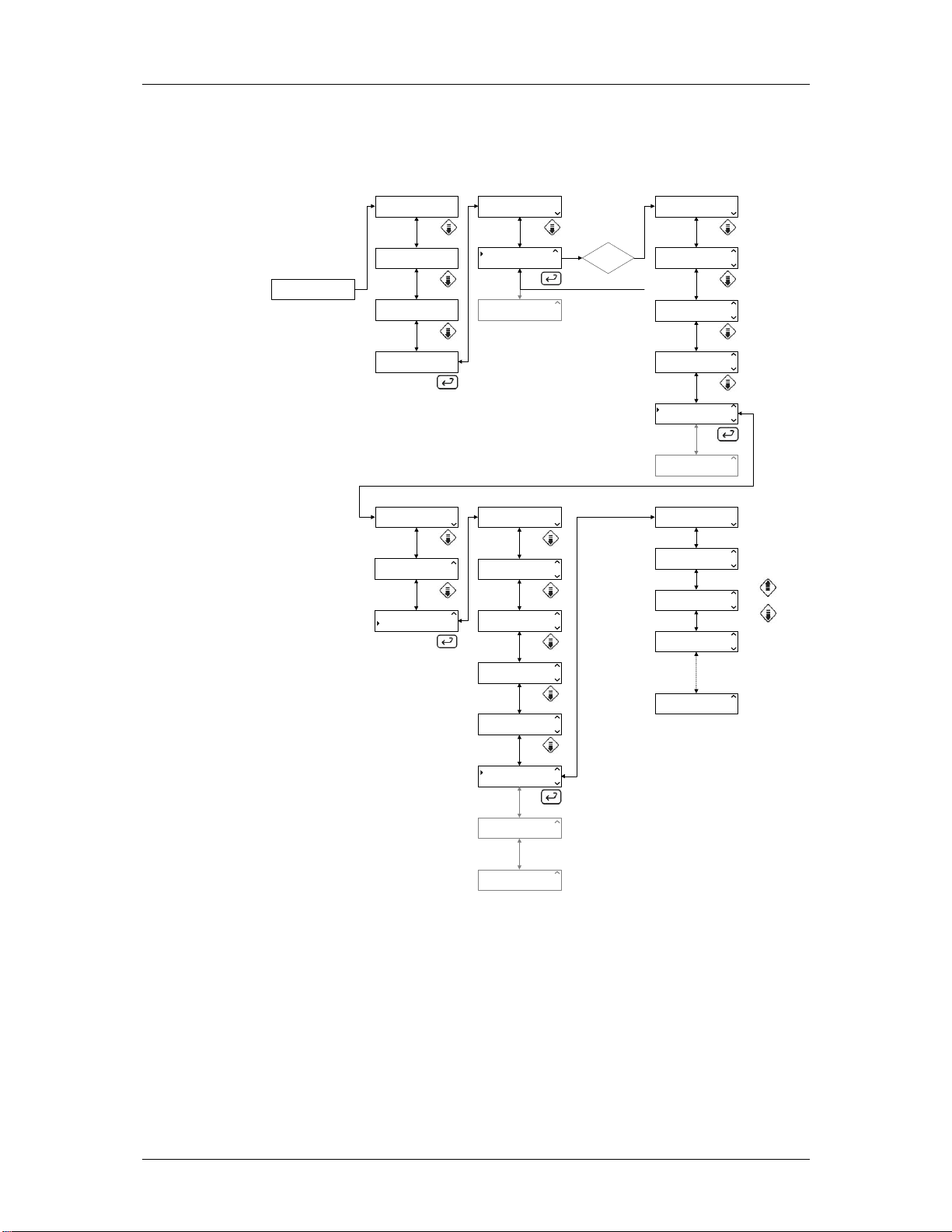
Software description and settings – Menu tree 31 (34)
Test system flag display (1.4.2.5.3.6)
These values are read-only. The state of each flag is displayed. The
different flags are pre-configured in the program. System flags see SwDS.
P01 PROGRAM NAME
60.0C
1.1
PRINT LAST CYCLE
SYSTEM
1.4.1
CALENDAR
CALIBRATION
1.4.2.1
GETINGE PACS 300
VERSION 3.5I (0283)
01 MACHINE NAME
02 PHASE NAME
1
START-INFO
00:00:00
SETUP
ERROR LOG
SERVICE MESSAGES
SERVICE MESSAGES
DIAGNOSTICS
SERVICE MESSAGES
DIAGNOSTICS
1.4.2.5.1
1.4.2.5.2
1.4.2.5.3
1.2
1.3
1.4
SYSTEM
ABOUT
SYSTEM
ABOUT
TEST ANALOG IN
TEST ANALOG OUT
TEST ANALOG OUT
TEST DIGITAL IN
TEST DIGITAL IN
TEST DIGITAL OUT
TEST DIGITAL OUT
TEST USER FLAGS
TEST USER FLAGS
TEST SYSTEM FLAGS
1.4.2.5.3.1
1.4.2.5.3.2
1.4.2.5.3.3
1.4.2.5.3.4
1.4.2.5.3.5
1.4.2
1.4.3
ENTER
PASSWORD
PW: E
CALIBRATION
CONFIGURATION
RETURN
CONFIGURATION
DIP SWITCHES
DIP SWITCHES
SERVICE
SERVICE
SAVE TO RAM FLASH
SERVICE
SAVE TO RAM FLASH
000 XXXXXXXX
0
001 XXXXXXXX
0
002 XXXXXXXX
0
003 XXXXXXXX
0
255 XXXXXXXX
0
1.4.2.2
1.4.2.3
1.4.2.4
1.4.2.5
1.4.2.6
1.4.2.5.3.6.1
1.4.2.5.3.6.2
1.4.2.5.3.6.3
1.4.2.5.3.6.4
1.4.2.5.3.6.257
TEST SYSTEM FLAGS
TEST PRINTER
TEST PRINTER
TEST LED/BUZZER
TEST PRINTER
TEST LED/BUZZER
1.4.2.5.3.6
1.4.2.5.3.7
1.4.2.5.3.8
4FS059-01
Utgåva 0402 Service instructions 5019675-00
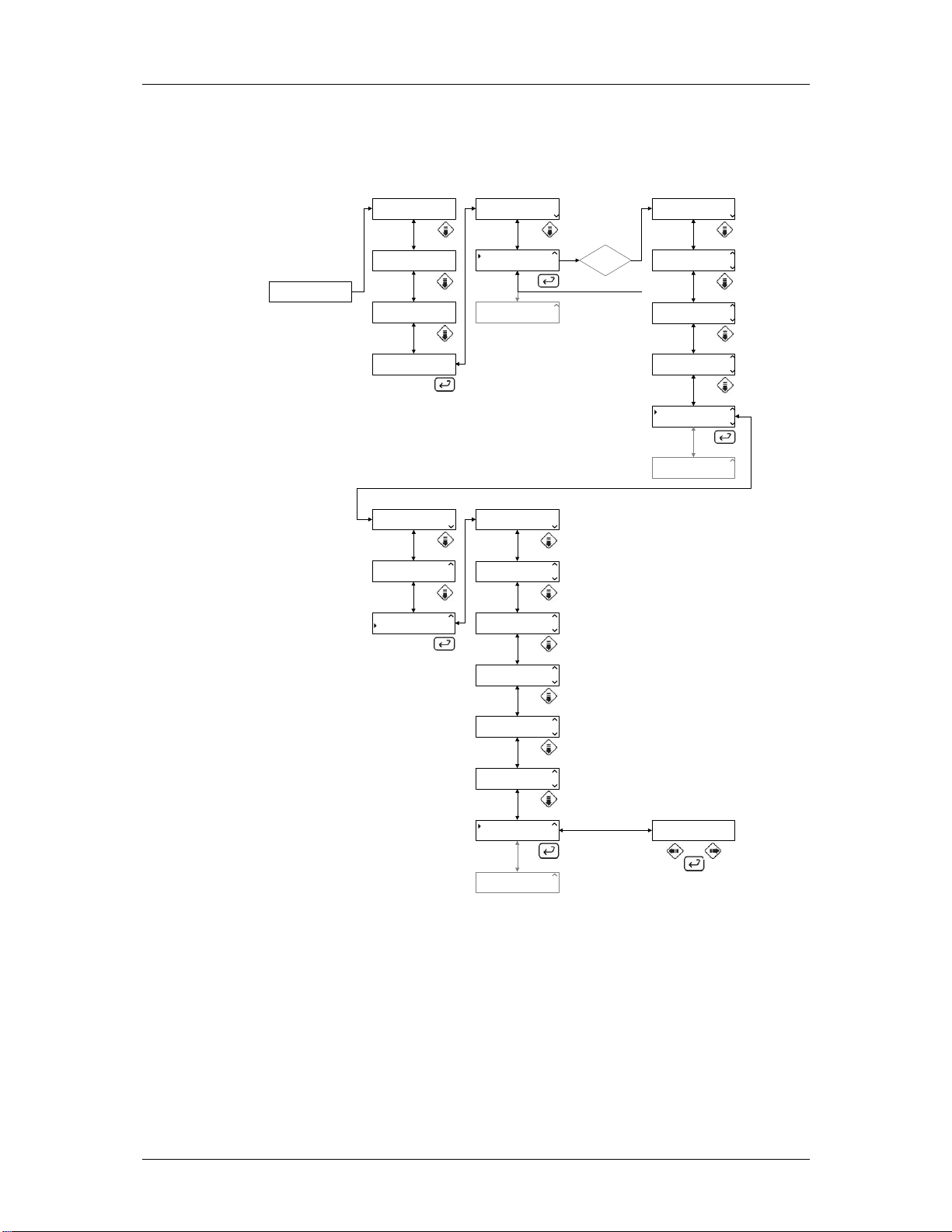
Software description and settings – Menu tree 32 (34)
Test printer (1.4.2.5.3.7)
When the printer is tested the printer writes characters on the paper.
GETINGE PACS 300
VERSION 3.5I (0283)
P01 PROGRAM NAME
PARAM 1 PARAM 2
01 MACHINE NAME
02 PHASE NAME
1
CYCLE COUNTER
00000
SETUP
ERROR LOG
SERVICE MESSAGES
SERVICE MESSAGES
DIAGNOSTICS
SERVICE MESSAGES
DIAGNOSTICS
1.4.2.5.1
1.4.2.5.2
1.4.2.5.3
1.1
1.2
1.3
1.4
PRINT LAST CYCLE
SYSTEM
SYSTEM
ABOUT
SYSTEM
ABOUT
TEST ANALOG IN
TEST ANALOG OUT
TEST ANALOG OUT
TEST DIGITAL IN
TEST DIGITAL IN
TEST DIGITAL OUT
1.4.1
1.4.2
1.4.3
1.4.2.5.3.1
1.4.2.5.3.2
1.4.2.5.3.3
ENTER
PASSWORD
PW: E
CALENDAR
CALIBRATION
CALIBRATION
CONFIGURATION
RETURN
CONFIGURATION
DIP SWITCHES
DIP SWITCHES
SERVICE
SERVICE
SAVE TO RAM FLASH
SERVICE
SAVE TO RAM FLASH
1.4.2.1
1.4.2.2
1.4.2.3
1.4.2.4
1.4.2.5
1.4.2.6
TEST DIGITAL OUT
TEST USER FLAGS
TEST USER FLAGS
TEST SYSTEM FLAGS
TEST SYSTEM FLAGS
TEST PRINTER
TEST PRINTER
TEST LED/BUZZER
TEST PRINTER
TEST LED/BUZZER
1.4.2.5.3.4
1.4.2.5.3.5
1.4.2.5.3.6
1.4.2.5.3.7
1.4.2.5.3.8
TEST PRINTER?
YES NO
4FS060-01
Utgåva 0402 Service instructions 5019675-00
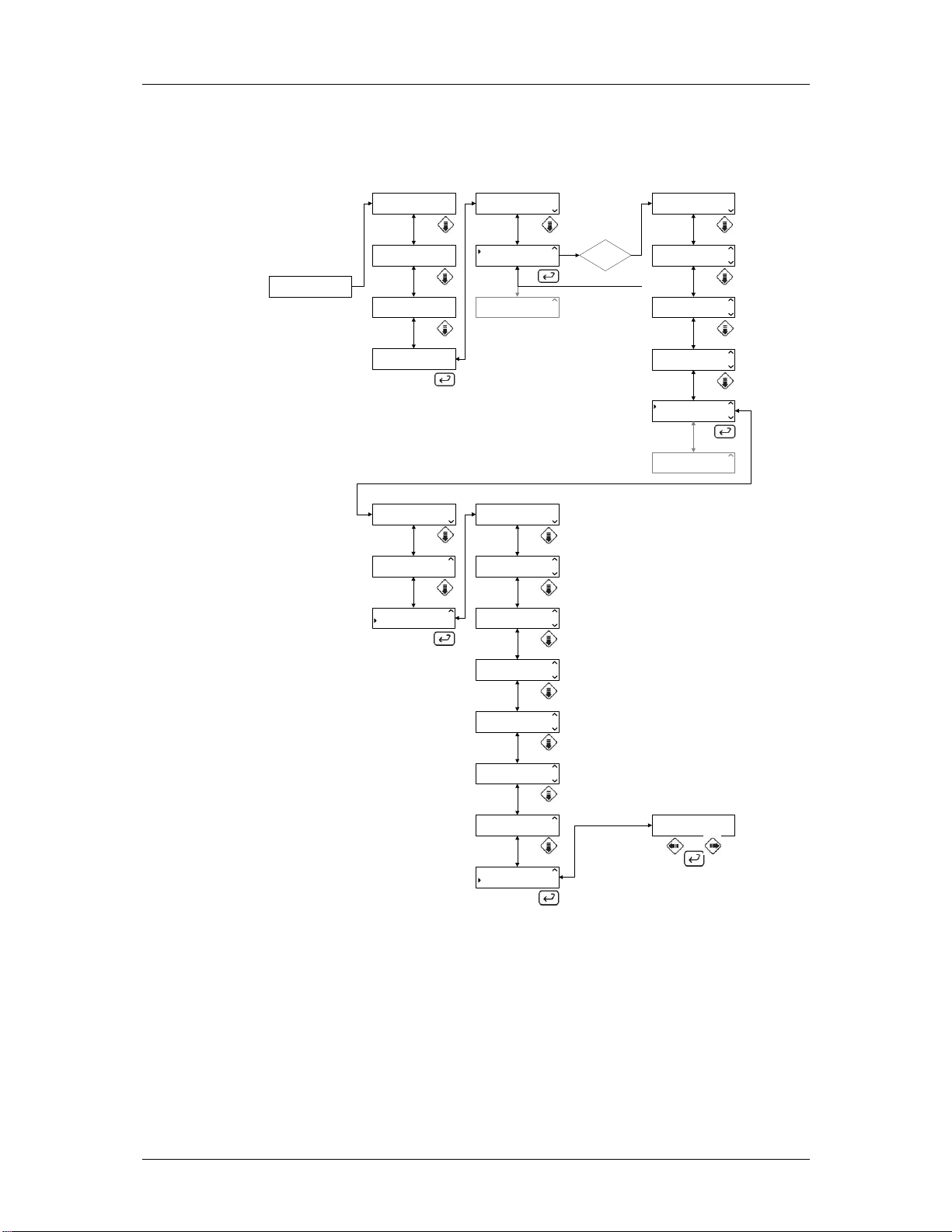
Software description and settings – Menu tree 33 (34)
Test LED/buzzer display (1.4.2.5.3.8)
All LED’s and the buzzer is turned on during the test.
GETINGE PACS 300
VERSION 3.5I (0283)
P01 PROGRAM NAME
PARAM 1 PARAM 2
01 MACHINE NAME
02 PHASE NAME
1
CYCLE COUNTER
00000
SETUP
ERROR LOG
SERVICE MESSAGES
SERVICE MESSAGES
DIAGNOSTICS
SERVICE MESSAGES
DIAGNOSTICS
1.4.2.5.1
1.4.2.5.2
1.4.2.5.3
1.1
1.2
1.3
1.4
PRINT LAST CYCLE
SYSTEM
SYSTEM
ABOUT
SYSTEM
ABOUT
TEST ANALOG IN
TEST ANALOG OUT
TEST ANALOG OUT
TEST DIGITAL IN
TEST DIGITAL IN
TEST DIGITAL OUT
1.4.1
1.4.2
1.4.3
1.4.2.5.3.1
1.4.2.5.3.2
1.4.2.5.3.3
ENTER
PASSWORD
PW: E
CALENDAR
CALIBRATION
CALIBRATION
CONFIGURATION
RETURN
CONFIGURATION
DIP SWITCHES
DIP SWITCHES
SERVICE
SERVICE
SAVE TO RAM FLASH
SERVICE
SAVE TO RAM FLASH
1.4.2.1
1.4.2.2
1.4.2.3
1.4.2.4
1.4.2.5
1.4.2.6
TEST DIGITAL OUT
TEST USER FLAGS
TEST USER FLAGS
TEST SYSTEM FLAGS
TEST SYSTEM FLAGS
TEST PRINTER
TEST PRINTER
TEST LED/BUZZER
TEST PRINTER
TEST LED/BUZZER
1.4.2.5.3.4
1.4.2.5.3.5
1.4.2.5.3.6
1.4.2.5.3.7
1.4.2.5.3.8
TEST LED/BUZZER?
YES NO
1.4.2.5.3.8.1
4FS061-01
Utgåva 0402 Service instructions 5019675-00

Software description and settings – Menu tree 34 (34)
Save ram to flash display (1.4.2.6)
The ram has battery backup, but during a could start the Pac’s reads from
the flash memory to ram and all changed done after the last save will be
lost.
GETINGE PACS 300
VERSION 3.5I (0283)
About display (1.4.3)
This displays the version of the different program parts in the PACS.
P01 PROGRAM NAME
PARAM 1 PARAM 2
01 MACHINE NAME
02 PHASE NAME
1
CYCLE COUNTER
00000
SETUP
P01 PROGRAM NAME
PARAM 1 PARAM 2
1.1
1.2
1.3
1.4
1.1
PRINT LAST CYCLE
SYSTEM
SYSTEM
ABOUT
SYSTEM
ABOUT
PRINT LAST CYCLE
SYSTEM
1.4.1
1.4.3
1.4.2
1.4.1
ENTER
PASSWORD
PW: C,E,F
CALENDAR
CALIBRATION
CALIBRATION
CONFIGURATION
RETURN
CONFIGURATION
DIP SWITCHES
DIP SWITCHES
SERVICE
SERVICE
SAVE TO RAM FLASH
SERVICE
SAVE RAM TO FLASH
PACS VERSION
3.5I (283)
1.4.2.1
1.4.2.2
1.4.2.3
1.4.2.4
1.4.2.5
1.4.2.6
1.4.3.1
SAVE CONFIRMATION?
YES NO
4FS062-01
1.4.2.6.1
1.4.3.2
1.4.3.3
1.4.3.4
GETINGE PACS 300
VERSION 3.5I (0283)
01 MACHINE NAME
02 PHASE NAME
1
CYCLE COUNTER
00000
SETUP
1.2
SYSTEM
ABOUT
1.3
SYSTEM
ABOUT
1.4
1.4.2
1.4.3
DISPLAY VERSION
3.4
LANGUAGE VERSI ON
8.1
DATABASE VERSION
1179-61F DB 3.21
Utgåva 0402 Service instructions 5019675-00
4FS063-01


Preventive maintenance
Preventive maintenance
Contents
General ___________________________________________________3
Periodic maintenance ________________________________________3
Function check _____________________________________________ 4
Instructions, cable, switch__________________________________ 4
Filter and valves _________________________________________ 4
Controls ________________________________________________ 4
Insert for goods __________________________________________ 4
Door___________________________________________________ 5
Detergent dosing _________________________________________ 5
Flush system ____________________________________________ 5
Temperature check _______________________________________ 5
Dryer __________________________________________________ 5
Printer (extra equipment) ___________________________________ 5
Service instructions
5019675-00Edition 0410


Preventive maintenance
General
The required maintenance interval will depend largely on the quality of the incoming water and
how often the machine is used. The maintenance interval will have to be determined in each
individual case. We recommend that the stated maintenance operations are done at the
specified intervals. We also recommend that a function check is done once or twice a year.
For repairs or adjustments, see under Repair and adjustment.
Periodic maintenance
This may only be done by authorised personnel.
The machine is connected to the electric power supply and voltage is present
on certain components.
Component Interval
Check Replace if Replace Replace every Replace every
yearly necessary every year other year 1000 hours
Door seal ••
Hoses between
dosing pump and detergent ••
container
Hose between dosing ••
pump and machine
Filter in incoming ••
media
Overheat protection ••
Hose in hose pump ••
Spray arm wings ••
Sterile filter in dryer ••
Hoses to dryer ••
Check valve in dryer ••
Check valve in waste outlet ••
Fan to dryer ••
Ink ribbon for printer ••
Spring •
on door closing
Dampers on door closing •
Service instructions
5019675-00Edition 0410

Function check
This must only be done by authorised personnel.
The machine is connected to the electric power supply and voltage is present
on certain components.
Instructions, cable, switch
• Check that a goods placing sign has been put up on the wall behind the disinfector.
• Check that the isolator switch on the wall is working and that the connecting cable is
undamaged and free from defects.
Filter and valves
• Check that level switches and manual shutoff valves are working properly.
• Check the filters in the supply line (see under Cleaning the filters in the supply line). Clean
when necessary.
• Check all pipe couplings. Tighten and seal if necessary.
Preventive maintenance
Controls
• The machine is operated with the buttons on the control panel.
• Check that the control buttons are working. If the buttons are working, a beep will be heard.
• While a program is running check that the yellow lamp at M is lit. When the program is
Insert for goods
• Check that the inserts for the machine dock properly with the water outlets.
• Check that spray arms (if fitted) rotate and are not clogged.
• Check that the goods to be cleaned are retained in the insert.
V190
Container
alarm
complete, the green lamp at N should light up.
5019675-00 Edition 0410
Service instructions

Door
Check that the door seal closes tight and is undamaged and that there is no leakage while a
program is running. Clean or replace the seal if necessary.
Detergent dosing
Check that the suction hose and pump are full of detergent or rinse-aid before running a
program. When the pre-programmed amount of detergent is changed, the consumption must be
checked with a measuring glass.
Flush system
• Check that the spray arms can rotate freely.
• Check that the holes in the washing arms are not blocked. Clean when necessary.
• Check that the coarse strainer in the bottom of the washing chamber is correctly installed.
Clean when necessary.
• Check that all couplings connecting the washing system to the pump and chamber are
leaktight. Tighten and seal if necessary.
Preventive maintenance
All supply lines must be closed when working on the pipe system.
Temperature check
• Check the temperature during a program run. Compare time and temperature with the program
sheet. Time and temperature are especially important in the disinfection phase.
The measuring equipment must be capable of registering temperature and time continuously.
High-performance equipment is essential for reliable measuring results, because of the
relatively rapid temperature changes.
Only one measuring point in the centre of the machine is need for the function check.
Note:
Washer-disinfectors that have been shown not to meet the requirements in terms
of temperature, sequence, washing system and safety must not be used until the
faults have been corrected.
Dryer
• Check seals and hoses for leaks once a year.
• Replace the sterile filter if necessary or in the event of an alarm.
Printer (extra equipment)
• Check ink ribbon cartridge
• Check the printout quality.
Service instructions
5019675-00Edition 0410


Fault indications and troubleshooting
Fault indications and troubleshooting
Contents
Fault indications ____________________________________________ 3
A red lamp lights up ______________________________________ 3
Messages ______________________________________________ 3
Fault codes _____________________________________________ 4
Acknowledging a fault code ________________________________ 4
Troubleshooting ____________________________________________5
Service instructions
5019675-00Edition 0410


Fault indications
Red lamp: Fault code
Fault indications and troubleshooting
Handling alarm or fault code
P01
Add detergent 1
V1624
A red lamp lights up
If the red lamp at O lights up, the process has been aborted because of a fault. If a handling
alarm is given, see below for the action to take. For other alarms, call service personnel.
Handling alarms
Messages appear in plain text on the display. The machine cannot be started until the fault has
been put right. The following messages can be displayed:
Dose 1 low level Empty container alarm 1. If detergent 1 is finished, a handling code is
Dose 2 low level Empty container alarm 2. If detergent 2 is finished, a handling code is
Dose 3 low level Empty container alarm 3. If detergent 3 is finished, an operation
Dose 4 low level Empty container alarm 4. If detergent 4 is finished, an operation
P02 OP-D
DOSE 1 LOW LEVEL
generated.
The alarm is reset automatically when detergent is added.
generated.
Reset av larm sker automatiskt när medel fylls på.
code is generated. The alarm is reset automatically when detergent is added.
code is generated. The alarm is reset automatically when detergent is added.
Note:
The last process had access to detergent. A message is displayed for future
processes.
Service instructions
5019675-00Edition 0410

Fault indications and troubleshooting
Error codes
P02 OP-D
F00 POWER FAIL
Fault codes indicate that a serious fault has occurred in the washing process. The fault must be
put right by an authorised service technician.
Acknowledging a fault code
Reset the fault code by:
1. pressing U. The alarm signal is silenced.
2 . Correct the fault.
3 . The machine is still locked but the current process has been aborted. Pressing V again
drains liquid from the machine and the dirty side door goes down.
Note:
If the draining pump is faulty, the water is not drained from the machine.
NOTE:
The goods in the machine are not clean. Start a new process.
5019675-00 Edition 0410
Service instructions

Fault indications and troubleshooting
Troubleshooting
The table below describes the fault codes that may be generated and a possible action for each
fault code.
This may only be done by authorised personnel.
The machine is connected to the electric power supply and voltage is present
on certain components.
Fault codeFault Comment
F00 Power failure If the power failure lasts for more than 59 seconds, the process is aborted. The
fault code is generated when the power returns.
F01 The motor cutout has tripped. The motor cutout (–F01) for the circulation pump has tripped.
Possible action:
a. Check that there is power on all phases from the circulation pump.
b. Check that the motor cutout is correctly set (see electrical diagram).
c. Check that the pump impeller rotates easily.
d. Check the direction of rotation (see installation instructions).
F02 Water filling too slow. The water level sensor (-B11) is not activated within ten minutes of filling starting.
Possible action:
a. Check that the shutoff valves are open and that water is reaching the
machine.
b. Check that the solenoid valves open and that their filters are not clogged.
c. Check that the strainer in the machine is not clogged.
F03 Emptying time too long Emptying takes longer than five minutes or the water level sensor (-B11) is still
activated when the emptying phase is complete.
Possible action:
a. Check that the waste pump pumps out water.
b. Check that the pressure switch changes over.
c. Check that the solenoid valve closes (water does not leak in).
d. Check that the strainer in the machine is not clogged.
F04 Water leakage in the dryer Switch to water level sensor (-B12) open.
Possible action:
a. Check that the check valves to the drying connection close.
F05 Fault door, dirty side Door does not lock (-S02) within 10 seconds or opens while a program is
running.
Possible action:
a. Check whether the microswitch (-S02) for the “door locked” limit position has
been activated within 10 seconds on door locking.
b. Check that the motor (-M16) and the switch (-S03) for door locking are
working.
Service instructions
5019675-00Edition 0410

Fault indications and troubleshooting
Fault codeFa ult Comment
F06 Door fault, dirty side The door does not unlock (-S02) within 10 seconds.
Possible action:
a. Check whether the microswitch (-S02) for the “door locked” limit position has
been activated within 10 seconds on door locking.
b. Check that the motor (-M16) and the switch (-S02) for door unlocking are
working.
F09 Faulty door, dirty side Door does not lock (-S05) within 10 seconds or opens while a program is
running.
Possible action:
a. Check whether the microswitch (-S05) for the “door locked” limit position has
been activated within 10 seconds on door locking.
b. Check that the motor (-M17) and the switch (-S07) for door locking are
working.
F10 Faulty door, dirty side The door does not unlock (-S05) within 10 seconds.
Possible action:
a. Check whether the microswitch (-S05) for the “door locked” limit position has
been activated within 10 seconds on door locking.
b. Check that the motor (-M17) and the switch (-S05) for door unlocking are
working.
F15 Flowmeter, dosing 1 Not enough detergent 1 dosed (-B16).
Possible action:
a. Check operation of the dosing pump.
b. Check that there is detergent in the container.
c. Check whether an empty container alarm has occurred.
d. Check that there is no air in the flowmeter and that it is rotating.
e. Check that the hoses are not blocked.
F16 Flowmeter, dosing 2 Not enough detergent 2 dosed (-B17)
Possible action:
a. Check operation of the dosing pump.
b. Check that there is detergent in the container.
c. Check whether an empty container alarm has occurred.
d. Check that there is no air in the flowmeter and that it is rotating.
e. Check that the hoses are not blocked.
F19 Flowmeter, dosing 3 Not enough detergent 3 dosed (-B20)
Possible action:
a. Check operation of the dosing pump.
b. Check that there is detergent in the container.
c. Check whether an empty container alarm has occurred.
d. Check that there is no air in the flowmeter and that it is rotating.
5019675-00 Edition 0410
Service instructions

Fault indications and troubleshooting
e. Check that the hoses are not blocked.
Fault codeFault Comment
F20 Flowmeter, dosing 4 Not enough detergent 4 dosed (-B21)
Possible action:
a. Check operation of the dosing pump.
b. Check that there is detergent in the container.
c. Check whether an empty container alarm has occurred.
d. Check that there is no air in the flowmeter and that it is rotating.
e. Check that the hoses are not blocked.
F23 High conductivity The conductivity (-U01) is higher than the set value after the third repeat rinse.
Possible action:
a. Check that the correct type of water is connected.
F24 Low pressure in dryer The differential pressure (-B03) is <150 Pa .
Possible action:
a. Check whether the fan, hoses or filter(s) are faulty.
b. When changing a filter, check that the new filter is correctly installed.
F25 High pressure in dryer The differential pressure (-B03) is > 750 Pa .
Possible action:
a. Check whether the filter is clogged.
F26 Low pressure from circulation pump The pressure (-B04) is <30 kPa.
Possible action:
a. Check the docking between machine and wash rack.
b. Check that the pump impeller rotates easily.
c. Check the direction of rotation (see installation instructions).
d. Check that the detergent is not foaming.
F27 High pressure from circulation pump The pressure (-B04) is > 130 kPa.
Possible action:
a. Check that no nozzles in the washing arms are blocked.
F28 Low temperature in dryer The temperature (-B05) has not risen to 20 degrees C below the set value after
two minutes.
Possible action:
a. Check that there is power on all phases up to the element.
F30 Faulty temperature sensor in washing chamber The temperature (-B07) is <0 °C or >130 °C.
Possible action:
a. Check the temperature sensor (for open-circuit or short-circuit)
Service instructions
5019675-00Edition 0410

Fault indications and troubleshooting
Fault codeFa ult Comment
F31 Faulty temperature sensor in washing Independent. The temperature (-B07) is <0 °C or >130 °C.
chamber Possible action:
a. Check the temperature sensor (for open-circuit or short-circuit)
F32 Faulty temperature sensor in dryer The temperature (-B05) is <0 °C or >130 °C.
Possible action:
a. Check the temperature sensor (for open-circuit or short-circuit)
F33 Incorrect temperature in washing chamber Wash temperature (-B07) has not risen by at least 10 degrees C after eight
minutes’ washing.
Possible action for electrically heated machine:
a. Check that there is power on all phases up to the elements.
b. Check the overheat protection of the elements.
Possible action for steam heated machine:
a. Check the steam valve.
b. Check that the ball valve is open and that the filter in the incoming steam is
clean.
c. Check steam pressure (see installation instructions).
d. Check condensate drain.
e. Check that there is no back pressure in the condensate drain.
F34 Faulty temperature sensor in washing chamber Wash temperature (-B07) dependent and independent differs by more than
±3 degrees C.
Possible action:
a. Check the calibration of the temperature sensor (see Calibration under
Repair and adjustment)
b. Check the temperature sensor.
F36 Error message from independent
monitoring system
5019675-00 Edition 0410
Service instructions

Repair and adjustment
Repair and adjustment
Contents
Connecting a PC____________________________________________ 3
Loading a program to flash memory_____________________________ 4
Load system program _____________________________________ 4
Load language files _______________________________________ 6
Cold start _________________________________________________9
Calibration _______________________________________________10
Conductivity meter ______________________________________ 1 0
Check the output signal from the conductivity meter _________ 10
Set the cell constant___________________________________ 10
Calibration __________________________________________ 11
Pressure sensor for circulation pump ________________________ 14
Temperature sensor – with resistor __________________________ 16
Temperature sensors – with ice bath and oil bath _______________ 18
Differential pressure gauge for dryer _________________________ 20
Replacing a temperature sensor ______________________________ 23
In wash chamber and dryer ________________________________ 23
Door ____________________________________________________24
Position and operation, door switches _______________________ 24
Remove panel __________________________________________ 2 5
Remove side panel_______________________________________ 26
Door switch ____________________________________________ 27
Replacing door switch _________________________________ 2 7
Adjusting door switches _______________________________ 27
Replacing the door seal ___________________________________ 28
Adjusting the closing pressure _____________________________ 29
Removing the door ______________________________________ 30
Separating the door (inner/outer door) _______________________ 30
Diagonal adjustment of the machine _________________________ 3 1
Adjusting docking to the wash trolley _______________________ 32
Resetting the overheat cutout ______________________________ 33
Cleaning the filters for incoming water. _______________________ 3 4
Dryer _________________________________________________ 35
Setting detergent and rinse-aid quantities_____________________ 36
Printer ________________________________________________ 36
Replacing the paper roll ________________________________ 3 6
Shutting down the printer ______________________________ 37
Activating the printer__________________________________ 37
Ribbon cartridge replacement ___________________________ 3 7
Jumpering an expansion card ________________________________38
Replacing a hose to a hose pump ______________________________ 39
Conductivity measurement ___________________________________40
Function in washing process ____________________________ 40
Measuring range _____________________________________ 40
Calibration __________________________________________ 40
Removing a measuring cell _____________________________ 4 0
Calibrating the conductivity equipment ______________________ 4 1
List of components _________________________________________42
Service instructions
5019675-00Edition 0410

Repair and adjustment
5019675-00 Edition 0410
Service instructions

Connecting a PC
An RS-232 cable is needed to connect a PC to the washer-disinfector.
Proceed as follows:
1 . Connect a cable between the PC and port X24 or X25 as shown below.
- X24 is mainly used for a PC and (for example) a scanner.
- X25 is used mainly for T-doc (RS485) and printer (RS232 or RS485).
Repair and adjustment
2 . Set type of communication. The communication settings are done in the service program; see
under tab 5 Software description and settings. Proceed as follows if the PC is:
connected to port X24
- Go into Communication setup COM 0 (1.4.2.3.5.1); see tab 5 Software description and
settings.
- Choose COMLI PROTOCOL and press S. Exit the service program.
connected to port X25
- Go into Communication setup COM 1 (1.4.2.3.5.2); see tab 5 Software description and
settings.
- Choose COMLI PROTOCOL and press S.
- Go into Communication setup COM 1 (1.4.2.3.5.3); see tab 5 Software description and
settings.
- Depending on the distance between the computer and the washer-disinfector, choose
communication speed RS232 (<5 m) or RS485 (>5 m)and press S. Exit the service
program.
Service instructions
5019675-00Edition 0410

Repair and adjustment
Loading a program to flash memory
The flash memory can be loaded with new wash programs or new system programs. Loading
new wash programs requires the CS-1000 program, which can be purchased from Getinge.
Instructions are supplied with CS-1000. System programs and language versions are loaded
with Flashloader.
Load system program
Note:
Always make a backup copy before starting work on updating system programs.
1 . Connect a PC to the machine; see under Connecting a PC.
2 . Check that the machine is in STANDBY mode.
3 . Make a backup copy by starting CS 1000 and choosing Tools/PACS RAM/Upload To File...
V1577
4 . Save the *.prm file in your chosen location.
The program will report an error during conversion. Disregard this. To check that
conversion was successful, check the size of the *.prm file. The size of the file should be
84416 bytes.
5 . Switch off the power to the machine with the main switch.
6 . Change the jumper (X29) on the board for the PACS 300 control system from Normal to Test.
X30
ON OFF
Norma
X29
TEST
X28
5019675-00 Edition 0410
Service instructions
Prom
Flash
V1544

Repair and adjustment
7 . Switch on the power to the machine with the main switch. The display should now show:
GETINGE
Ram OK
or
GETINGE PACS 300
Version X.XX (XXXX)
8 . Start Flashloader from PC.
9. Set up as shown.
File name Choose the right program file (*.a37).
Com Port The port to which you connected the data cable to your PC.
Baudrate Choose 57600
All Sectors and Verbose must be checked (=selected).
10. Start loading by pressing Program !. The following image appears.
V1578
V1579
Service instructions
5019675-00Edition 0410

Repair and adjustment
11. When loading is complete, the following image appears. Press OK.
V1580
12. Now the display shows:
SW Update 0x2497
Updating CRC....
A beep is heard and the display shows:
SW Update 0x2497
CRC OK
13. Check that the battery jumper (X30) is set to ON.
14. Switch off the power to the machine with the main switch.
15 . Change the jumper (X29) to Normal.
16. Switch on the power to the machine with the main switch. The display should now show:
P00
17 . Close Flashloader.
18 . Start CS-1000 and load wash programs; see instructions for CS-1000.
Load language files
Note:
Always make a backup copy before starting work on updating system programs.
1 . Connect a PC to the machine; see under Connecting a PC.
2 . Check that the machine is in STANDBY mode.
3 . Make a backup copy by starting CS 1000 and choosing Tools/PACS RAM/Upload To File...
4 . Save the *.prm file in your chosen location.
The program will report an error during conversion. Disregard this. To check that
conversion was successful, check the size of the *.prm file. The size of the file should be
84416 bytes.
5 . Switch off the power to the machine with the main switch.
V1577
5019675-00 Edition 0410
Service instructions

Repair and adjustment
6 . Change the jumper (X29) on the board for the PACS 300 control system from Normal to Test.
X30
ON OFF
Norma
X29
TEST
X28
7. Set up as shown.
Filename Choose the right program file (*.a37).
Com Port The port to which you connected the data cable to your PC.
Baudrate Choose 57600
All Sectors and Verbose must be checked (=selected).
Prom
Flash
V1544
V1578
Service instructions
5019675-00Edition 0410

Repair and adjustment
8. Choose the Language tab.
9 . Choose the relevant files:
- Language support file,
- Language file for PACS database.
10. Set Flash Sector for Language to 8 and 10 (as shown).
11 . Check (select) Transfer.
11 . Click Transfer->. The language files are now transferred to PACS 300.
12 . Close Flashloader.
V1581
5019675-00 Edition 0410
Service instructions

Cold start
Repair and adjustment
Do a cold start when the machine has hung and you cannot proceed with the program.
1 Switch off the power to the machine.
2 Move the battery jumper (X30) to Off.
3 Move the programming jumper (X29) from Normal to Cold.
4 Switch on the power.
5 Wait until CRC OK appears on the display.
6 Move the battery jumper (X30) back to On. Note: The power is still on.
7 Switch off the power.
8 Move the programming jumper (X29) from Cold to Normal.
9 Switch on the power.
10 Set the doors to the home position using the service program (tab 5 Software description
and settings, Test digital output display (1.4.2.5.3.4)) or CS1000.
Home position for the doors:
Soiled side = door unlocked and open
Clean side = door closed and locked
X29
Norma
TEST
X28
X30
ON OFF
Prom
Flash
Service instructions
V1544
5019675-00Edition 0410

Repair and adjustment
Calibration
Conductivity meter
Check the output signal from conductivity meter
To check the output signal, proceed as follows.
1. Press [ on the conductivity meter.
2 . Enter code 22 with Y and Z.
3. Press [. Setup 1 appears.
4 . Choose Output with Y and Z.
5. Press [. Sel. Type appears on the lower line.
6 . Choose with Y and Z. Lin appears on the top line.
7. Press [.
8 . Choose 4-20 mA with Y and Z.
9. Press [.
10 .Set with Y and Z so that 0/4 mA =0.000 µS/cm.
11 .Press [.
12 .Set with Y and Z so that 20 mA = 200 µS/cm.
13 .Press [.
14.Press Y and Z at the same time to log out.
Set the cell constant
To set the cell constant, proceed as follows:
1. Press [.
2 . Enter code 22 with Y and Z.
3. Press [. Setup 1 appears.
4. Press [ until the display shows Cellconst.
5. With Y and Z, set the relevant cell constant; see the calibration certificate.
6. Press [.
7. Press Y and Z at the same time to log out.
5019675-00 Edition 0410
Service instructions
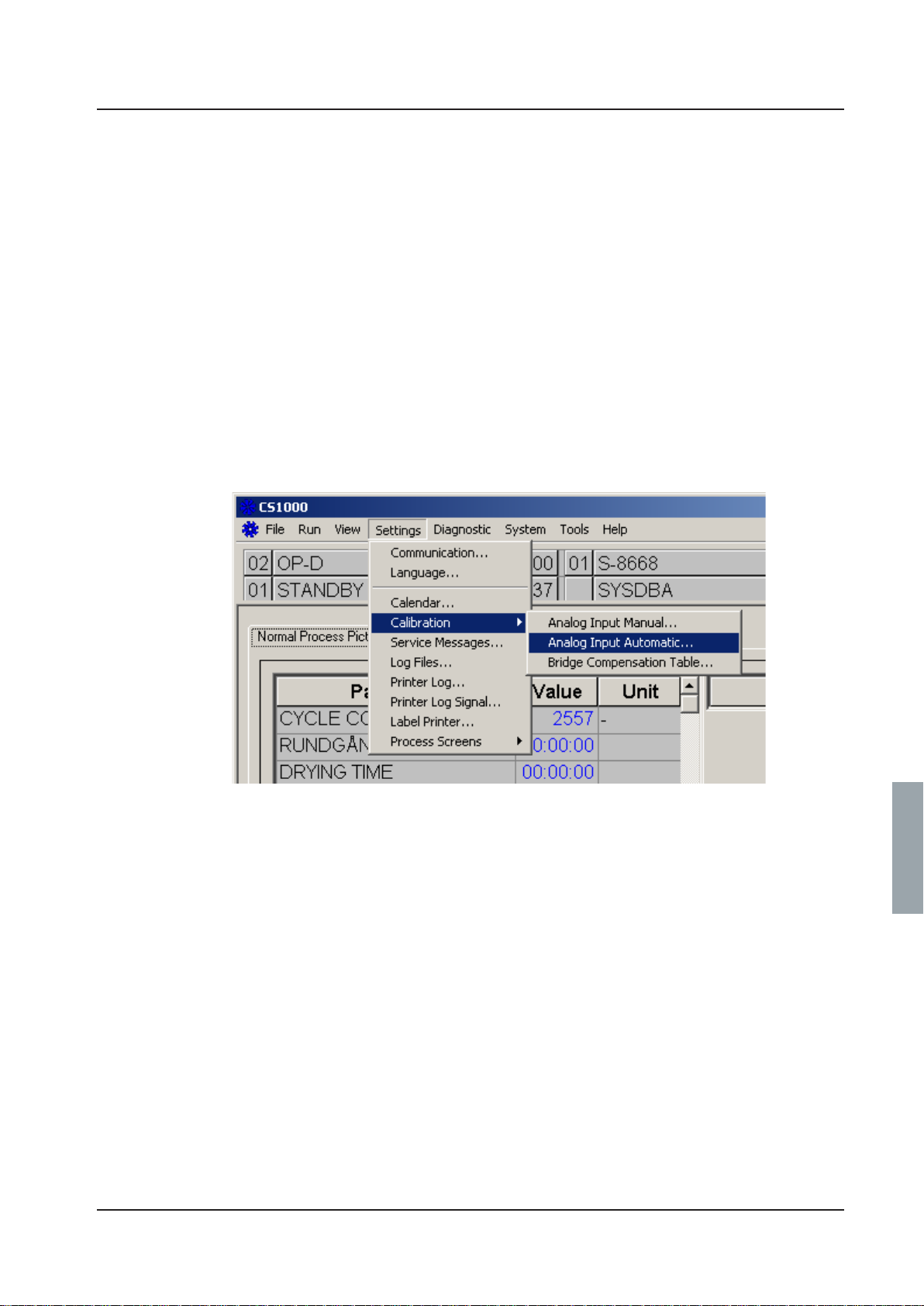
Calibration
Repair and adjustment
To calibrate the conductivity meter, proceed as follows.
1 . Connect a PC with the CS 1000 program installed to the disinfector.
2. Press [ on the conductivity meter.
3 . Enter code 22 with Y and Z.
4. Press [. Setup 1 appears.
5 . Choose Output with Y and Z.
6. Press [. Sel. Type appears.
7 . Choose SIM with Y and Z.
8. Press [.
9 . Choose to 0…22 mA with Y and Z.
10 . Set 4 mA.
11. Start CS 1000 and choose Settings/Calibration/Analog Input Automatic...
Service instructions
V1563
5019675-00Edition 0410

Repair and adjustment
12 .Click Conductivity (A) and then Calibrate (B).
A
V1564
B
13 .Enter the value 0 (A) and click Set Low.
V1565
5019675-00 Edition 0410
Service instructions
A

Repair and adjustment
14 . Set 20 mA on the conductivity meter with Y and Z.
15 . Enter 200 (A) in CS 1000 and click Set High.
A
V1566
B
16. Check that the value (B) rises to 200.
17 . Log off CS 1000.
18. Press Y and Z at the same time. Output appears on the display.
19. Press [. Sel. Type appears.
20 . Choose Lin. with Z.
21 . Press [.
22. Press Y and Z at the same time twice to log out of the conductivity meter.
Service instructions
5019675-00Edition 0410

Repair and adjustment
Pressure sensor for circulation pump
To calibrate the pressure sensor for the circulation pump, proceed as follows.
1. Connect a PC with the CS 1000 program installed to the disinfector.
2 . Connect a process simulator to A01-X2;
+ to 2
- to 5.
3 . Set the process simulator to 4 mA.
4 . Start CS 1000 and choose Settings/Calibration/Analog Input Automatic...
V1563
5 . Click Pump pressure (A) and then Calibrate (B).
A
B
V1567
5019675-00 Edition 0410
Service instructions

Repair and adjustment
6 . Enter the value 0 (A) and click Set Low.
A
7 . Set the process simulator to 20 mA.
8 . Enter 160 (A) in CS 1000 and click Set High.
V1568
A
B
9 . Check that the value (B) rises to 160.
10. Log off CS 1000.
Service instructions
V1569
5019675-00Edition 0410

Repair and adjustment
Temperature sensor – with resistor
Proceed as follows to calibrate the temperature sensors with the aid of resistors:
1. Connect a PC with the CS 1000 program installed to the disinfector.
2. Insert resistors for 20 ºC at the following places:
A01-X7 Chamber temperature (two sensors)
A01-X6 Booster tank
A01-X5 Dryer
3 . Start CS 1000 and choose Settings/Calibration/Analog Input Automatic...
V1563
4 . Click Temp booster, Temp chamber and Temp chamb indep(A), then click Calibrate (B).
B
A
V1571
5019675-00 Edition 0410
Service instructions

Repair and adjustment
5 Enter the value 20 (A) and click Set Low.
A
B
6 Check that the value (B) rises to 20.
7 Replace resistors for 20 ºC with resistors for 90 ºC.
8 Enter 90 (A) in CS 1000 and click Set High.
V1571
B
9 . Check that the value (B) rises to 90.
10. Log off CS 1000.
11. Remove the resistors and reinstate the temperature sensors.
Service instructions
A
V1572
5019675-00Edition 0410

Repair and adjustment
Temperature sensors – with ice bath and oil bath
Proceed as follows to calibrate the temperature sensors with the aid of resistors:
1. Connect a PC with the CS 1000 program installed to the disinfector.
2 . Prepare an ice bath and an oil bath.
The ice bath must consist of crushed ice in a bowl of cold water. The bath must stand for at
least 20 minutes so that the temperature can stabilise.
The oil bath must be switched on for at least 45 minutes at the set temperature (100 ºC) to
stabilise the temperature.
3. Remove the temperature sensors from the disinfector. Tape the sensors together.
4 . Lower the temperature sensors into the ice bath together with an external thermometer.
5 . Start CS 1000 and choose Settings/Calibration/Analog Input Automatic...
V1563
6 . Click Temp booster, Temp chamber and Temp chamb indep(A), then click Calibrate (B).
B
A
V1570
5019675-00 Edition 0410
Service instructions

Repair and adjustment
7 Check that the reading of the external thermometer stabilises. Enter the reading of the external
thermometer (A) and click Set Low.
A
V1571
B
8 Check that the value (B) rises to the set value.
9 Move the temperature sensors and the external thermometer to the oil bath. Check that the
reading of the external thermometer stabilises. Enter the reading of the external thermometer
(A) and click Set High.
B
10.Check that the value (B) rises to the set value.
11 .Log off CS 1000.
12. Re-instate the temperature sensors.
Service instructions
A
V1572
5019675-00Edition 0410
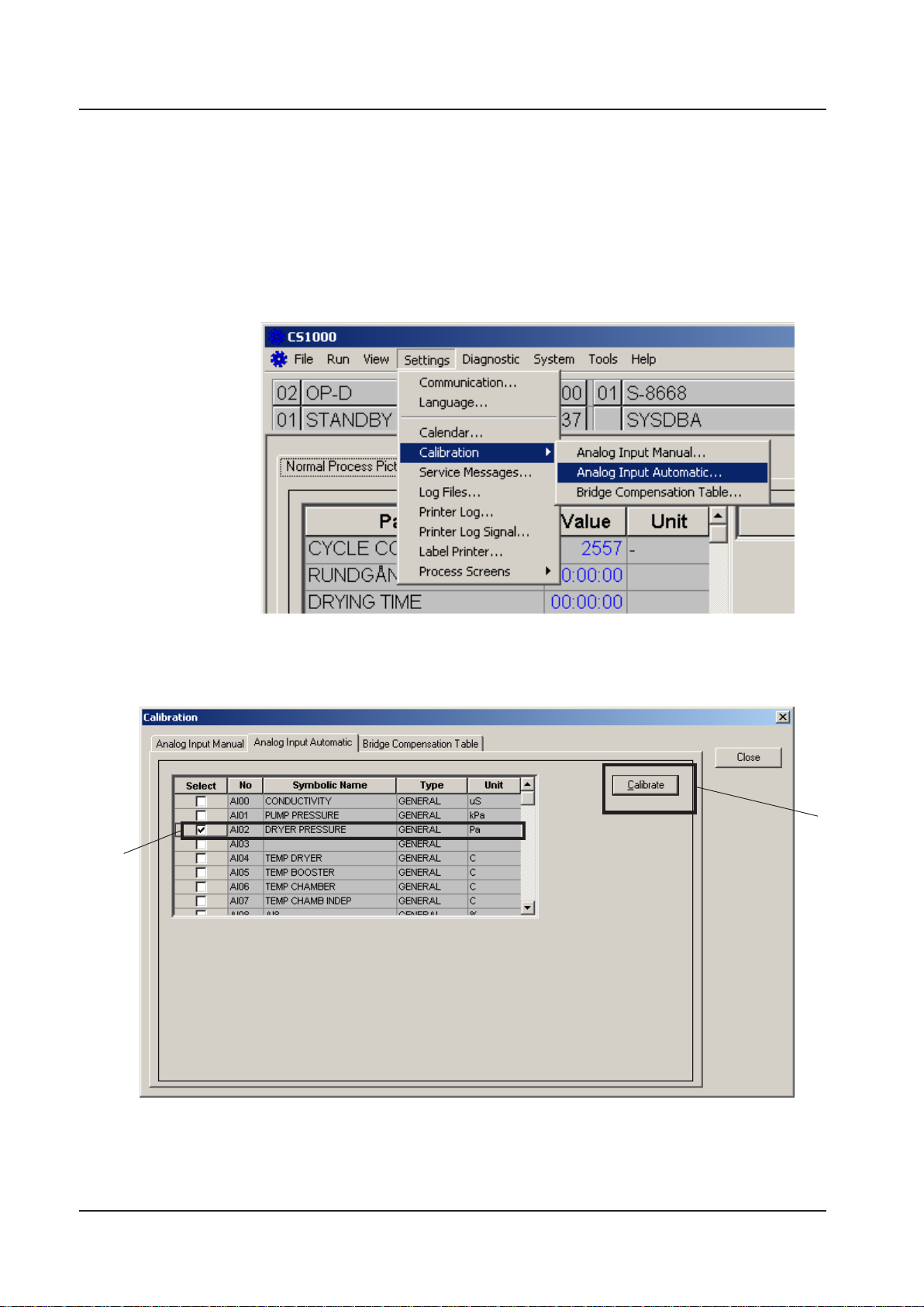
Repair and adjustment
Differential pressure gauge for drying unit
To calibrate the differential pressure gauge for the dryer, proceed as follows.
1 . Connect a PC with the CS 1000 program installed to the disinfector.
2 . Close the machine doors.
3 . Connect an external differential pressure gauge in parallel with the existing gauge on the
machine. Zero the external differential pressure gauge.
4 . Start CS 1000 and choose Settings/Calibration/Analog Input Automatic...
V1563
5 . Click Dryer pressure (A) and then Calibrate (B).
B
A
V1573
5019675-00 Edition 0410
Service instructions
 Loading...