

Page 1

SETUP & OPERATION MANUAL
FEATURES
On/off safety switch with lock-out key to prevent
unauthorized use.
Helical cutter head for superior finish and quieter operation.
Built-in 2 1/2” dust collection outlet.
Powerful 1 HP, 120 V, 10 amp motor.
4” x 19 5/8” adjustable, tilting fence with 45° and
90° stops.
Spring-loaded cutter head guard.
Two safety push blocks included.
Easy to set-up and operate.
Front-mounted infeed table lock.
6″ BENCH-TOP JOINTER
-
WITH HELICAL CUTTER HEAD
SPECIFICATIONS
• Table size
29 7/8” x 6 1/8” (760 x 156 mm)
• Table height
8 1/4” (210 mm)
• Maximum cutting width
6” (152 mm)
• Maximum cutting depth
1/8” (3 mm)
• Fence size
4 1/4” x 19 5/8” (110 x 500 mm)
• Number of insert
12
• Cutter head speed
11,000 rpm
• Dust outlet
2 1/2” (64 mm)
• Base dimensions
19 1/4” x 9 7/16” (490 x 240 mm)
• Motor
1 HP, 120 V, 10A
• Weight (shipping/net)
37,5 lbs (17 kg) / 41 lbs (18,7 kg)
Version #1 - October 2014
© Copyright General International
MODEL
#
80-025HC
Page 2

GENERAL® INTERNATIONAL
8360 Champ-d’Eau, Montreal (Quebec) Canada H1P 1Y3
Telephone (514) 326-1161 • Fax (514) 326-5555 • www.general.ca
THANK YOU
for choosing this General® International model 80-025HC 6”
bench-top helical head jointer. This jointer has been carefully tested and inspected before
shipment and if properly used and maintained, will provide you with years of reliable service.
For your safety, as well as to ensure optimum performance and trouble-free operation, and to
get the most from your investment, please take the time to read this manual before assembling,
installing and operating the unit.
The manual’s purpose is to familiarize you with the safe operation, basic function, and
features of this jointer as well as the set-up, maintenance and identification of its parts and
components. This manual is not intended as a substitute for formal woodworking instruction,
nor to offer the user instruction in the craft of woodworking. If you are not sure about the safety
of performing a certain operation or procedure, do not proceed until you can confirm, from
knowledgeable and qualified sources, that it is safe to do so.
Once you’ve read through these instructions, keep this manual handy for future reference.
DISCLAIMER: The information and specifications
in this manual pertain to the unit as it was supplied
from the factory at the time of printing. Because we
are committed to making constant improvements,
General® International reserves the right to make
changes to components, parts or features of this
unit as deemed necessary, without prior notice and
without obligation to install any such changes on
previously delivered units. Reasonable care is taken
at the factory to ensure that the specifications and
information in this manual corresponds with that of the
unit with which it was supplied. However, special orders
and “after factory” modifications may render some or
all information in this manual not applicable to your
machine. Further, as several generations of this model
of jointer and several versions of this manual may be in
circulation, if you own an earlier or later version of this
unit, this manual may not depict your unit exactly. If you
have any doubts or questions contact your retailer or
our support line with the model and serial number of
your unit for clarification.
Page 3

GENERAL® INTERNATIONAL WARRANTY
All component parts of General® International and Excalibur by General International® products
are carefully inspected during all stages of production and each unit is thoroughly inspected upon
completion of assembly.
Limited Lifetime Warranty
Because of our commitment to quality and customer satisfaction, General® International agrees to
repair or replace any part or component which upon examination, proves to be defective in either
workmanship or material to the original purchaser for the life of the tool. However, the Limited Lifetime
Warranty does not cover any product used for professional or commercial production purposes nor
for industrial or educational applications. Such cases are covered by our Standard 2-year Limited
Warranty only. The Limited Lifetime Warranty is also subject to the “Conditions and Exceptions” as listed
below.
Standard 2-Year Limited Warranty
All products not covered by our lifetime warranty including products used in commercial, industrial
and educational applications are warranted for a period of 2 years (24 months) from the date of
purchase. General® International agrees to repair or replace any part or component which upon
examination, proves to be defective in either workmanship or material to the original purchaser during
this 2-year warranty period, subject to the “conditions and exceptions” as listed below.
To file a Claim
To file a claim under our Standard 2-year Limited Warranty or under our Limited Lifetime Warranty,
all defective parts, components or machinery must be returned freight or postage prepaid to
General® International, or to a nearby distributor, repair center or other location designated by
General® International. For further details call our service department at 1-888-949-1161 or your local
distributor for assistance when filing your claim.
Along with the return of the product being claimed for warranty, a copy of the original proof of purchase
and a “letter of claim” must be included (a warranty claim form can also be used and can be obtained,
upon request, from General® International or an authorized distributor) clearly stating the model and
serial number of the unit (if applicable) and including an explanation of the complaint or presumed
defect in material or workmanship.
CONDITIONS AND EXCEPTIONS:
This coverage is extended to the original purchaser only. Prior warranty registration is not required but
documented proof of purchase i.e. a copy of original sales invoice or receipt showing the date and
location of the purchase as well as the purchase price paid, must be provided at the time of claim.
Warranty does not include failures, breakage or defects deemed after inspection by
General® International to have been directly or indirectly caused by or resulting from; improper use,
or lack of or improper maintenance, misuse or abuse, negligence, accidents, damage in handling or
transport, or normal wear and tear of any generally considered consumable parts or components.
Repairs made without the written consent of General® International will void all warranty.
Page 4

TABLE OF CONTENTS
Rules for safe operation ..................................................................................................... 5
Electrical requirements ...................................................................................................... 6
Identification of main parts and components .................................................................. 7
Unpacking .......................................................................................................................... 8
Basic functions ................................................................................................................... 8
Assembly instructions ................................................................................................... 9-12
Installing the jointer on a table surface ........................................................................................................... 9
Assembling and installing the fence ........................................................................................................... 9-11
Installing the lock-out key ................................................................................................................................ 11
Installing the dust port ................................................................................................................................. 11-12
Connecting to a dust collector ....................................................................................................................... 12
Basic adjustments and controls ................................................................................. 12-16
Connecting to a power source .......................................................................................................................12
On/Off power switch .........................................................................................................................................13
Checking/adjusting the depth of cut indicator zero point .................................................................... 13-14
Setting the 90° and 45° fence stops ........................................................................................................... 14-16
Front to back fence adjustment ..................................................................................................................... 16
Operating Instructions ................................................................................................ 17-18
Basic principles of jointing ............................................................................................................................... 17
Selecting boards suitable for jointing ............................................................................................................ 17
Determine the concave face and edge of your board .............................................................................17
Checklist before starting .................................................................................................................................. 18
Basic jointing operations ............................................................................................ 18-19
Surface planing ................................................................................................................................................. 18
Edge jointing ..................................................................................................................................................... 18
Maintenance ............................................................................................................... 19-22
Inspecting cutter head inserts ......................................................................................................................... 19
Reversing/replacing cutter head inserts ....................................................................................................... 20
Motor brush replacement ............................................................................................................................... 21
Belt replacement .............................................................................................................................................. 21
Periodic maintenance ..................................................................................................................................... 22
Recommended optional accessories ............................................................................. 22
Parts list & diagrams ................................................................................................... 23-26
Contact information ........................................................................................................ 28
Page 5

RULES FOR SAFE OPERATION
To help ensure safe operation, please take a moment to learn the machine’s applications and limitations,
as well as potential hazards. General
harmless for any injury that may result from the improper use of it’s equipment.
1. Do not operate this jointer when tired, distracted,
or under the effects of drugs, alcohol or any me dication that impairs reflexes or alertness.
2. The work area should be well lit, clean and free
of debris.
3. Keep children and visitors at a safe distance when
the jointer is in operation; do not permit them to
operate the jointer.
4. Childproof and tamper proof your shop and all
machinery with locks, master electrical switches
and switch keys, to prevent unauthorized or unsu pervised use.
5. STAY ALERT! Give your work your undivided attention.
Even a momentary distraction can lead to serious
injury.
6. Fine particulate dust is a carcinogen that can be
hazardous to health. Work in a well-ventilated area
and whenever possible use a dust collector. Wear
face, eye, ear, respiratory and body protection
devices.
7. Do not wear loose clothing, gloves, bracelets, neck- laces or other jewelry while the jointer is in opera tion. Wear protective hair covering to contain long
hair and wear non-slip footwear.
®
International disclaims any real or implied warranty and hold itself
12. Do not push or force stock into the cutterhead. The
jointer will perform better and more safely when
working at the rate for which it was designed.
13. Be sure that the cutterhead has gained full opera ting speed before starting to joint.
14. Avoid working from awkward or off balance posi tions. Do not overreach and keep both feet on floor.
15. Keep guards in place and in working order. If a
guard must be removed for maintenance or clean ing be sure it is properly re-attached before using
the tool again.
16. Use of parts and accessories NOT recommended
by General
malfunction or risk of injury.
17. Never stand on machinery. Serious injury could
result if the tool is tipped over or if the cutting tool is
unintentionally contacted.
18. Always disconnect the tool from the power source
before servicing or changing accessories such as
knives, or before performing any maintenance or
cleaning, or if the machine will be left unattended.
19. Make sure that the switch is in the “OFF” position be- fore plugging in the power cord.
®
International may result in equipment
8. Be sure that adjusting wrenches, tools, drinks and
other clutter are removed from the machine and/or
the table surface before operating.
9. Keep hands well away from cutter head and all
moving parts. Use a push stick to feed stock, and a
brush, not hands, to clear away chips and dust.
10. Be sure that the cutter head inerts are securely in
stalled in the cutter head.
11. Always use clean, properly sharpened inserts.
Dirty or dull inserts are unsafe and can lead to
accidents.
20. Make sure the tool is properly grounded. If equip ped with a 3-prong plug it should be used with
a three-pole receptacle. Never remove the third
prong.
21. Do not use this jointer for any purpose other than
its intended use. If used for other purposes, General
International disclaims any real or implied warranty
and holds itself harmless for any injury, which may
result from that use.
®
5
Page 6
ELECTRICAL REQUIREMENTS
BEFORE CONNECTING THE MACHINE TO THE POWER SOURCE, VERIFY THAT THE VOLTAGE OF YOUR POWER
SUPPLY CORRESPONDS WITH THE VOLTAGE SPECIFIED ON THE MOTOR I.D. NAMEPLATE. A POWER SOURCE
WITH GREATER VOLTAGE THAN NEEDED CAN RESULT IN SERIOUS INJURY TO THE USER AS WELL AS DAMAGE
TO THE MACHINE. IF IN DOUBT, CONTACT A QUALIFIED ELECTRICIAN BEFORE CONNECTING TO THE POWER
SOURCE.
THIS TOOL IS FOR INDOOR USE ONLY. DO NOT EXPOSE TO RAIN OR USE IN WET OR DAMP LOCATIONS.
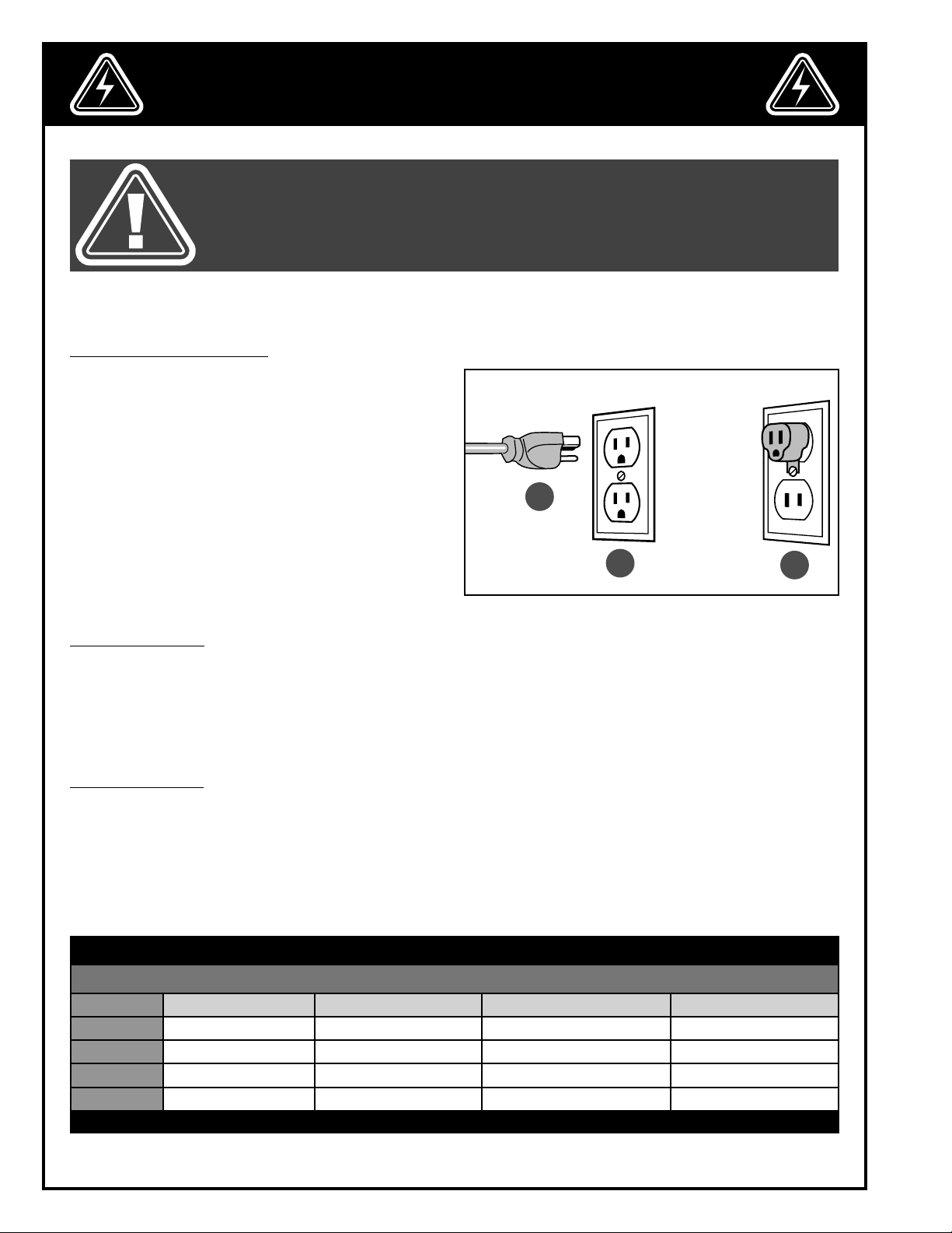
GROUNDING INSTRUCTIONS
In the event of an electrical malfunction or short circuit,
grounding reduces the risk of electric shock. The motor
of this machine is wired for 120 V single phase operation and is equipped with a 3-conductor cord and
a 3-prong grounding plug A to fit a grounded type
receptacle B. Do not remove the 3rd prong (grounding pin) to make it fit into an old 2-hole wall socket or
extension cord. If an adaptor plug is used C, it must be
attached to the metal screw of the receptacle.
Note: The use of an adaptor plug is illegal in some
areas. Check your local codes. If you have any doubts
or if the supplied plug does not correspond to your
electrical outlet, consult a qualified electrician before
proceeding.
A
B
C
CIRCUIT CAPACITY
Make sure that the wires in your circuit are capable of handling the amperage draw from your machine, as well
as any other machines that could be operating on the same circuit. If you are unsure, consult a qualified electrician. If the circuit breaker trips or the fuse blows regularly, your machine may be operating on a circuit that is
close to its amperage draw capacity. However, if an unusual amperage draw does not exist and a power failure
still occurs, contact a qualified technician or our service department.
EXTENSION CORDS
If you find it necessary to use an extension cord with your machine, use only 3-wire extension cords that have
3-prong grounding plug and a matching 3-pole receptacle that accepts the tool’s plug. Repair or replace a damaged extension cord or plug immediately.
Make sure the cord rating is suitable for the amperage listed on the motor I.D. plate. An undersized cord will cause
a drop in line voltage resulting in loss of power and overheating. The accompanying chart shows the correct size
extension cord to be used based on cord length and motor I.D. plate amp rating. If in doubt, use the next heavier
gauge. The smaller the number, the heavier the gauge.
TABLE - MINIMUM GAUGE FOR CORD
EXTENSION CORD LENGTH
AMPERES 50 feet 100 feet 200 feet 300 feet
< 5
6 to 10
10 to 12
12 to 16
*NR = Not Recommended
18 16 16 14
18 16 14 12
16 16 14 12
14 12 *NR *NR
6
Page 7

IDENTIFICATION OF MAIN PARTS AND COMPONENTS
C
B
A
D
G
F
E
I
H
A. DUST OUTLET
B. OUTFEED TABLE
C. FENCE
D. CUTTER HEAD GUARD
E. INFEED TABLE LOCK KNOB
F. DEPTH OF CUT INDICATOR
G. INFEED TABLE
H. INFEED TABLE ADJUSTMENT KNOB
I. SAFETY SWITCH WITH LOCK-OUT KEY
7
Page 8
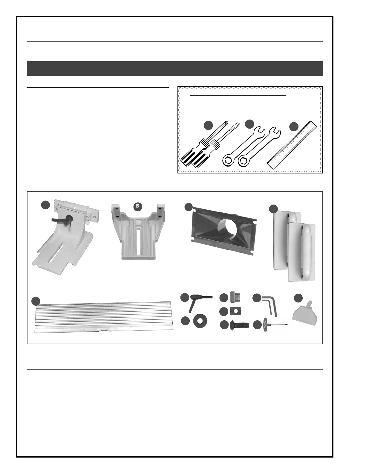
UNPACKING
Carefully unpack and remove the unit and its components from the box and check for missing or damaged items
as per the list of contents below.
NOTE: PLEASE REPORT ANY DAMAGED OR MISSING ITEMS TO YOUR GENERAL® INTERNATIONAL DISTRIBUTOR IMMEDIATELY.
LIST OF CONTENTS QTY
A. FENCE MOUNT ASSEMBLY ....................................................... 1
B. FENCE BRACKET ...................................................................... 1
C. DUST OUTLET ............................................................................ 1
D. PUSH BLOCKS .......................................................................... 2
E. FENCE FACE ............................................................................. 1
F. LOCK LEVER ............................................................................. 1
G. FLAT WASHER ............................................................................ 1
H. SQUARE NUT ............................................................................ 2
I. RECTANGULAR NUT ................................................................. 1
J. CAP SCREW ............................................................................. 6
K. 4 & 2.5 MM ALLEN KEYS ........................................................ 2
L. TORX™ WRENCH ..................................................................... 1
M. LOCK-OUT KEY ......................................................................... 1
ADDITIONAL REQUIREMENTS FOR SET UP
A. PHILLIPS AND FLAT SCREWDRIVERS
B. 10 AND 13 MM WRENCH
C. STRAIGHTEDGE
A
B
C
A
E
BASIC FUNCTIONS
B
C
F
G
H
I
J
D
K
L
M
This 6” jointer benchtop with helical cutter head is designed for face and edge jointing in solid wood only.
The unit is not designed nor should it be used to surface or prepare, plywood, wood paneling, particleboard, MDF
nor any other wood based by-products nor any non-wood based materials.
The unit is equipped with 12 reversible high-speed steel inserts that have two cutting faces each.
Warning! To reduce the risks of accidents leading to injury make sure to always properly secure the jointer
to your work surface before operating it.
8
Page 9
ASSEMBLY INSTRUCTIONS
BEFORE ASSEMBLING, MAKE SURE THAT THE SWITCH IS IN THE “OFF” POSITION AND THAT THE POWER CORD IS
UNPLUGGED. DO NOT PLUG IN OR TURN ON THE MACHINE UNTIL YOU HAVE COMPLETED THE ASSEMBLY AND
INSTALLATION STEPS DESCRIBED IN THIS SECTION OF THE MANUAL.
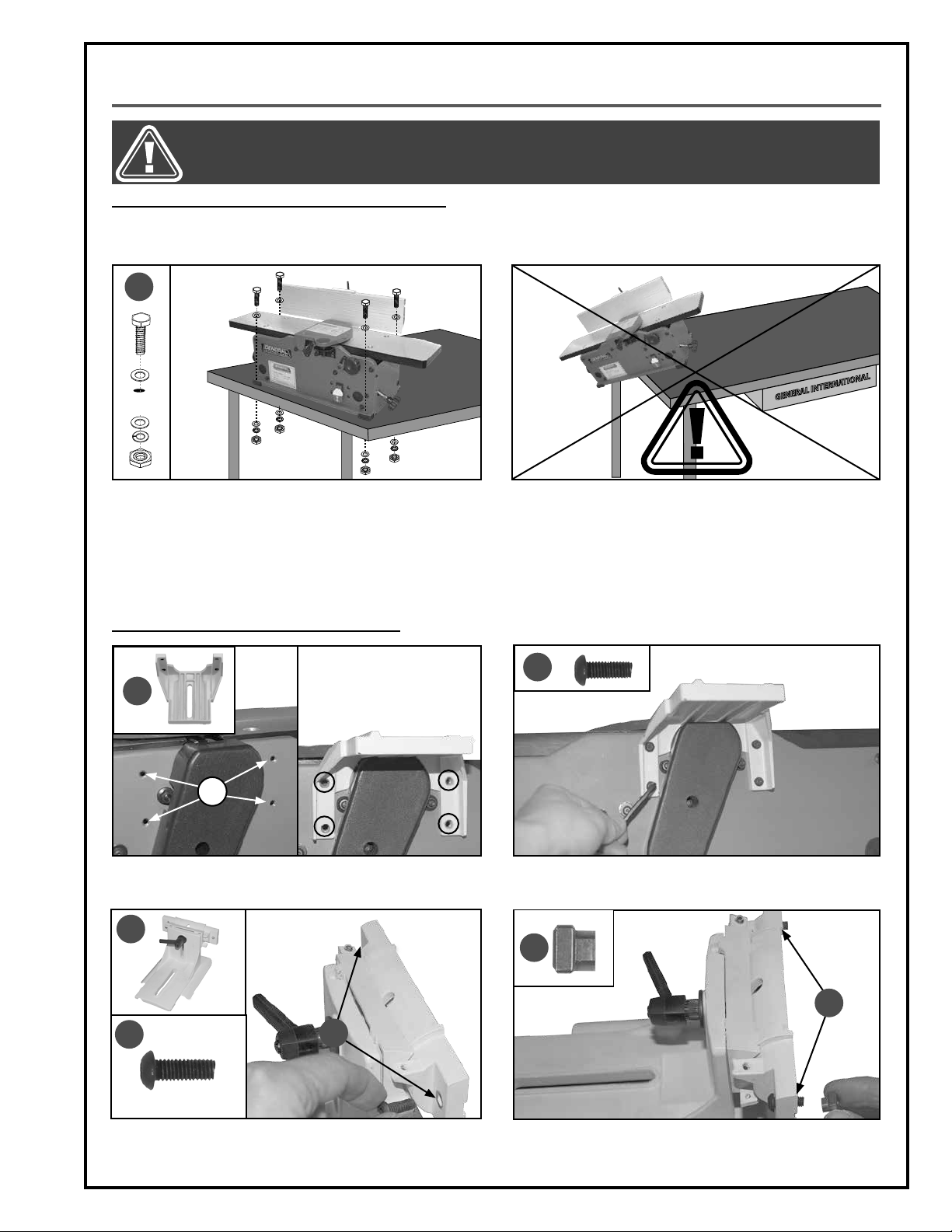
INSTALLING THE JOINTER ON A STABLE SURFACE
For your convenience this jointer is shipped from the factory partially assembled and requires only minimal
assembly and set up before being put into service.
A
L
A
N
O
I
T
A
N
R
E
T
N
I
L
A
R
E
N
E
G
The unit should be immobilized on a flat, level and stable surface, able to support the weight of the machine
and the workpiece with ease. Drill holes in the mounting surface corresponding with the holes located in
the base of the machine. Immobilize the unit using
hardware A (not supplied) in the order shown.
ASSEMBLING AND INSTALLING THE FENCE
B
C
1. Install the fence bracket B by aligning its four mount-
ing holes with the corresponding holes on the machine C.
E
Note: Never install or operate the unit over the edge
of a table, workbench or other mounting surface.
D
2. Attach the bracket to the machine using four
screws D and a 4 mm Allen key.
H
F
G
3. Insert a screw F into each hole G of the fence hold-
er E.
I
4. Loosely thread a square nut H onto each screw I.
9
Page 10

BEFORE ASSEMBLING, MAKE SURE THAT THE SWITCH IS IN THE “OFF” POSITION AND THAT THE POWER CORD IS
UNPLUGGED. DO NOT PLUG IN OR TURN ON THE MACHINE UNTIL YOU HAVE COMPLETED THE ASSEMBLY AND
INSTALLATION STEPS DESCRIBED IN THIS SECTION OF THE MANUAL.
ASSEMBLING AND INSTALLING THE FENCE (CONTINUED)
A
B
5. Slide the T-slot on the back of the fence onto the
nuts B on the fence holder A.
C
CENTER
CENTER
6. Center the fence on the holder.
7. Secure the fence tightening screws C with a 4 mm
8. Place the assembly on the fence bracket.
Allen key.
9. Slide a flat washer onto the lever. 10. Insert the lever with its flat washer in the hole in the
fence holder.
10
Page 11

BEFORE ASSEMBLING, MAKE SURE THAT THE SWITCH IS IN THE “OFF” POSITION AND THAT THE POWER CORD IS
UNPLUGGED. DO NOT PLUG IN OR TURN ON THE MACHINE UNTIL YOU HAVE COMPLETED THE ASSEMBLY AND
INSTALLATION STEPS DESCRIBED IN THIS SECTION OF THE MANUAL.
ASSEMBLING AND INSTALLING THE FENCE (CONTINUED)
A
A
B
11. Screw the lock lever to the rectangular nut A.
Note: Position the nut with the flat side up.
INSTALLING THE SWITCH LOCK-OUT KEY
1. Insert the key into the switch as shown. 2. Make sure the switch is in the OFF position.
INSTALLING THE DUST PORT
12. Place the fence against the table, and lock the
fence with the levers B.
C
D
1. Remove screw C using a 4 mm Allen key and the
screw D with a Phillips screwdriver.
E
F
2. Slide the dust port notch E onto the screws F.
11
Page 12

BEFORE ASSEMBLING, MAKE SURE THAT THE SWITCH IS IN THE “OFF” POSITION AND THAT THE POWER CORD IS
UNPLUGGED. DO NOT PLUG IN OR TURN ON THE MACHINE UNTIL YOU HAVE COMPLETED THE ASSEMBLY AND
INSTALLATION STEPS DESCRIBED IN THIS SECTION OF THE MANUAL.
INSTALLING THE DUST PORT (CONTINUED)
A
3. Retighten screws A. 4. Retighten self-tapping screws in the lower left and
right corners of the jointer.
CONNECTING TO A DUST COLLECTOR
A dust port that fits
2 1/2”
hose is provided to accom-
modate connection to a dust collector (not included).
Be sure to use appropriate sized hose and fittings (not
included).
Check that all connections are sealed tightly to help
minimize airborne dust. If you do not already own
a dust collection system consider contacting your
General® International distributor for information
on our complete line of dust collection systems and
I
L
A
R
E
N
E
G
L
A
N
O
I
T
A
N
R
E
T
N
accessories or visit our Web Site at www.general.ca.
BASIC ADJUSTMENTS & CONTROLS
TO REDUCE THE RISK OF SHOCK OR FIRE DO NOT OPERATE THE UNIT WITH A DAMAGED POWER CORD OR PLUG. REPLACE DAMAGED CORD OR PLUG IMMEDIATELY. TO AVOID UNEXPECTED OR UNINTENTIONAL START-UP, MAKE SURE
THE POWER SWITCH IS IN THE OFF POSITION BEFORE CONNECTING TO A POWER SOURCE.
CONNECTING TO A POWER SOURCE
Once the assembly steps have been completed, plug
the power cord into an appropriate outlet.
Refer back to the section entitled “Electrical Require
ments” and make sure all requirements and grounding
instructions are followed.
When operations have been completed unplug the
machine from the power source.
12
SWITCH OFF
-
TO AVOID UNEXPECTED OR UNINTENTIONAL
START-UP, MAKE SURE THAT THE POWER SWITCH
IS IN THE OFF POSITION BEFORE CONNECTING
TO A POWER SOURCE.
Page 13

MAKE SURE THE MACHINE HAS BEEN TURNED OFF AND UNPLUGGED FROM THE POWER SOURCE BEFORE PERFORMING ANY MAINTENANCE OR ADJUSTMENTS.
ON/OFF POWER SWITCH
The machine is equipped with a rocker type ON/OFF switch that is equipped with a lock-out key.
To prevent unwanted or unauthorized start-up remove the lock-out key A and store it in a safe place.
To start the machine, insert the lock-out key and pull the switch B up.
To stop the machine, push down on the switch C. When the machine comes to a complete stop, remove the lockout key A by gently pulling it outward.
A
LOCK-OUT KEY
(PREVENTS START-UP WHEN REMOVED)
B
POWER ON
C
POWER OFF
CHECKING / ADJUSTING THE DEPTH OF CUT INDICATOR ZERO POINT
The depth of cut indicator has been factory set to read “0” when the infeed table is at the exact same height as the
highest point of the cutter head. However with use and vibration over time, it may eventually become necessary
to re-adjust the zero point stop bolt and depth of cut indicator. Proceed as follows, if needed:
1. Loosen the guard screws and remove the guard. 2. Loosen the depth of cut lock knob.
D
3. Set the depth of cut indicator to "0" by turning knob
D clockwise.
4. Place a straightedge across the two tables.
13
Page 14

MAKE SURE THE MACHINE HAS BEEN TURNED OFF AND UNPLUGGED FROM THE POWER SOURCE BEFORE PERFORMING ANY MAINTENANCE OR ADJUSTMENTS.
CHECKING / ADJUSTING THE DEPTH OF CUT INDICATOR ZERO POINT (CONTINUED)
A C
B
5. Make sure the two tables are at the same height A.
If the infeed table is higher or lower than the outfeed table, go to the next step.
6. Re-adjust the height of the tables C by turning the
depth of cut knob B as needed.
E
D
7. Lock the infeed table in position turning the depth
of cut lock knob, then loosen screw D using a 4
mm Allen key and set the indicator at "0". Retighten
screw D and re-install the cutter head guard.
SETTING THE 90° & 45° FENCE STOPS
The fence stops allow you to position the fence at specific pre-set angles in relation to the tables without having
to measure each time you return to that angle. Due to wear and vibration, fence stops can over time become
misaligned and should be checked periodically and re-set if necessary.
Note: The cutter head guard has been removed for clarity.
To adjust the 90° stop:
Note: the threaded rod E on the lock knob serves as
the zero point stop. To avoid damaging the threaded
rod, do not force the depth of cut adjustment above
zero.
90°
1. Place a machinists square on the table and
against the fence. if the fence is not square to the
table, go to the next step.
14
A
2. Loosen the lever A.
Page 15

MAKE SURE THE MACHINE HAS BEEN TURNED OFF AND UNPLUGGED FROM THE POWER SOURCE BEFORE PERFORMING ANY MAINTENANCE OR ADJUSTMENTS.
SETTING THE 90° & 45° FENCE STOPS (CONTINUED)
B
C
3. Set the fence to 90°, then turn the set screw B until it
touches the fence bracket C.
4. Retighten the lock lever once the adjustment is
complete.
To adjust the 45° stop:
D
1. Loosen the lever D. 2. Raise the fence as shown.
3. Tilt the fence back as shown 4. Sit the fence on the table as shown.
15
Page 16

MAKE SURE THE MACHINE HAS BEEN TURNED OFF AND UNPLUGGED FROM THE POWER SOURCE BEFORE PERFORMING ANY MAINTENANCE OR ADJUSTMENTS.
SETTING THE 90° & 45° FENCE STOPS (CONTINUED)
To adjust the 45° stop (continued):
45°
A
B
5. Place a square on the table and against the fence
as shown.
6. Turn the set screw A until it touches the fence bracket B.
MOVING THE FENCE FRONT TO BACK
C
1. Loosen the lever C as shown . 2. Loosen the lever D as shown.
D
3. Raise the fence as shown.
16
4. Move the fence front as shown untill the desired position, then retighten the levers.
Page 17

MAKE SURE THE MACHINE HAS BEEN TURNED OFF AND UNPLUGGED FROM THE POWER SOURCE BEFORE PERFORMING ANY MAINTENANCE OR ADJUSTMENTS.
OPERATING INSTRUCTIONS
BASIC PRINCIPLES OF JOINTING
This jointer is designed to remove material from one face of a board in order to make it (or a series of boards) perfectly flat A.
This perfectly flat face is then placed against the fence, set at 90º to the tables, to obtain a perfectly perpendicular
90º flat edge B.
A
SELECTING BOARDS SUITABLE FOR JOINTING
ALWAYS JOINT IN THE GENERAL DIRECTION OF THE GRAIN. JOINTING AGAINST THE GRAIN OR JOINTING END
GRAIN IS DANGEROUS AND MAY CAUSE THE WORKPIECE TO SHATTER.
This jointer is not intended (and should not be used) to
joint any material other than solid wood.
1. Jointing safety begins with the stock used with the
machine. Inspect the work piece carefully before
jointing it. Never joint a board that has loose knots,
staples, nails or other embedded foreign objects. If
you have the slightest doubt about the structural
integrity or stability of a board:
2. Only boards with the grain running more or less
length-wise are suitable for jointing C.
Do Not Joint It
.
B
C
GRAIN DIRECTION
GRAIN DIRECTION
DETERMINE THE CONCAVE FACE AND EDGE OF YOUR BOARD
Place your board on a flat surface to identify its con
concave face and edge against the jointer table.
cave face D and edge E. The boards must be jointed with the
D
E
17
Page 18

CHECKLIST BEFORE STARTING
VERIFY ALL CHECK POINTS BEFORE STARTING. FAILURE TO COMPLY CAN RESULT IN SERIOUS INJURIES.
• Make sure you and any assistants are wearing safe appropriate workshop attire. Roll up long sleeves, secure
long hair and remove any jewelry: watches, rings, bracelets or anything that could become caught in the
moving parts, potentially causing serious injury.
• Make sure the board has been inspected and is suitable for jointing as explained in the previous section
“Selecting boards suitable for jointing”.
Verify that the cutter head guard is functioning properly (snaps back against the fence and covers the knives).
•
• Make sure that the fence is properly set and locked in place.
• Make sure to have on safety glasses as well as hearing and respiratory protection at all times when using the
jointer.
BASIC JOINTING OPERATIONS
FAILURE TO USE PUSH BLOCKS WHEN SURFACE PLANING MAY RESULT IN SERIOUS PERSONAL INJURY. ALWAYS USE
PUSH BLOCKS TO HELP KEEP YOUR HANDS AT A SAFE DISTANCE FROM THE KNIVES WHEN SURFACE PLANING.
SURFACE PLANING
1. Inspect the stock before starting & remove any for-
eign objects or debris.
2. Set the depth of cut as required (1/32” is recom-
mended for face planing - Less for hard wood or
wider stock.)
3. Set & lock the fence at 90°.
4. If your workpiece is cupped, place the cupped
side face down on the infeed (right) table.
5. Set the position of the fence so that the length of
blade remaining exposed is roughly 1/4” longer
than the width of the board to be jointed.
6. Turn on the machine & using push blocks press the
stock against the table and tight to the fence, feeding the stock over the cutter head.
7. Inspect the board & repeat the steps if needed until the surface is flat.
EDGE JOINTING
1. Inspect the stock before starting & remove any for-
eign objects or debris.
2. Set the depth of cut as required (1/16” - 1/8” is rec-
ommended for edge jointing - Less for hard wood
or wider stock.)
3. Set & lock the fence at 90°.
4. If your workpiece is cupped, place the cupped
side face down on the infeed (right) table.
5. Set the position of the fence so that the length of
blade remaining exposed is roughly 1/4” longer
than the width of the board to be jointed.
6. Turn on the machine, press the stock against the
table and tight to the fence, feeding the stock over
the cutter head.
7. Inspect the board & repeat the steps if needed until the surface is flat.
18
Page 19

MAKE SURE THE MACHINE HAS BEEN TURNED OFF AND UNPLUGGED FROM THE POWER SOURCE BEFORE PERFORMING ANY MAINTENANCE OR ADJUSTMENTS.
MAINTENANCE
INSPECTING CUTTER HEAD INSERTS
There are 12 high-speed steel inserts installed in the cutter head A at the factory. With use and normal wear over
time, it will eventually become necessary to reverse and/or replace the inserts.
To maintain even insert wear always reverse or replace all 12 inserts each time replacement is required. When
needed, replacement inserts B can be ordered through your local General International distributor under part
#30-007.
A
B
C
*EACH INSERT A HAS TWO CUTTING EDGES C. WHEN ONE OF
THEM IS BLUNTED OR DAMAGED, SIMPLY ROTATE THE INSERTION TO USE THE OTHER EDGE.
Observing jointed workpieces as they come off of the machine and looking for signs of knife damage or wear is
the best method to help you to determine when knives are due to be changed.
Signs to look for include:
1. A raised ridgeline in the workpiece that runs a
straight line from beginning to end of the board
D. This is generally an indication that one or more
knives has been nicked or damaged E by a foreign
object such as a nail, staple or other hard object
hidden or embedded in the workpiece.
2. A slight washboard or chatter effect F which can
be an indication of uneven knife wear causing one
knife to cut slightly deeper than the others.
3. Rough, irregular, torn or fuzzy grain on a freshly
jointed surface may be a sign of worn or dull
blades causing the wood to tear out. Sharp blades
cut crisply and leave a relatively smooth finish.
D
E
Note: Fuzzy grain can also be a sign of high moisture
content in the workpiece. If knives have recently
been changed or if you suspect that moisture content and not dull inserts is the cause, set the workpiece aside and test by jointing other boards with
known or acceptable moisture content.
If the jointed results using a different workpiece are
smooth, then moisture content in your wood is the
problem - no adjustments can be made to the machine for this. Set the “wet” stock aside and simply
work with drier wood.
F
19
Page 20

MAKE SURE THE MACHINE HAS BEEN TURNED OFF AND UNPLUGGED FROM THE POWER SOURCE BEFORE PERFORMING ANY MAINTENANCE OR ADJUSTMENTS.
REVERSING/REPLACING CUTTER HEAD INSERTS
Note: The cutter head guard has been removed for clarity,
1. Unplug the machine from the power source and
remove the lock-out key from the switch.
B
A
3. Immobilize the cutter head using a 4 mm Allen key
A, and remove the 12 inserts using the supplied
Torx™ key B. Thoroughly clean the housing and
cavity before turning/replacing an insert.
2. Loosen the cutter head guard screws, and remove
the guard.
C
D
E
4. Thoroughly clean the inserts C and screws D using
a lacquer thinner and small brush then apply a
light coating of machine oil on the screws, takingcare to remove any excess.
Note: When turning the inserts in the cutter head, refer to the etched mark E on the inserts to keep track
of the rotations.
5. Place each insert in the housing and firmly secure it
in place with a screw.
Note: To avoid stripped screws and cracked inserts,
do not overtighten the screws
20
6. Re-install the cutter head guard before starting the
machine.
Page 21

MAKE SURE THE MACHINE HAS BEEN TURNED OFF AND UNPLUGGED FROM THE POWER SOURCE BEFORE PERFORMING ANY MAINTENANCE OR ADJUSTMENTS.
MOTOR BRUSH REPLACEMENT (AFTER ABOUT 150 HOURS OF SERVICE)
Note: Replace the brush when its length is less than 6 mm.
A
B
1. Unplug the machine from the power source and
remove the lock-out key from the switch. Tilt the
machine back to access the motor and remove
2. Remove the motor brush from its housing as shown.
Install the new brush in its housing, then re-install
the cap B.
the brush cap A with a screwdriver.
BELT REPLACEMENT
Inspect the belt afler every 100 hours of service. Belts that show visible signs of wear such as cracks or fraying at the
edges should be replaced immediately.
TO REDUCE RISK OF INJURY KEEP FINGERS ON TOP OF
THE THE BELT
1. Remove the fence with a 4 mm Allen key, then re-
move the belt cover with the same key.
2. Pull back on the belt while turning one of the pul-
leys counterclockwise until the belt comes off the
pulley.
TO REDUCE RISK OF INJURY KEEP FINGERS ON TOP OF
THE THE BELT
3. Install the belt on the lower pulley, then slide the
belt onto the edge of the upper pulley. Turn the upper pulley until the belt snaps into place.
4. Re-install the blade guard and the pulley cover be-
fore starting the machine
21
Page 22

MAKE SURE THE MACHINE HAS BEEN TURNED OFF AND UNPLUGGED FROM THE POWER SOURCE BEFORE PERFORMING ANY MAINTENANCE OR ADJUSTMENTS.
PERIODIC MAINTENANCE
To prolong the service life of your jointer and to maintain optimum performance, the following basic maintenance
procedures should be practiced and become part of your shop routine.
• Inspect/test the ON/OFF switch before each use. Do not operate the jointer with a damaged switch; replace
a damaged switch immediately.
• Keep the machine as well as the infeed outfeed tables clean and free of saw dust, woodchips, pitch or
glue. Vacuum or brush off any loose debris and wipe down the machine and the tables occasionally with a
damp rag.
• An occasional light coating of paste wax can help protect the tables surface and reduce workpiece friction.
Ask your local distributor for suggestions on aftermarket surface cleaners, protectant and dry lubricants
based on what is readily available in your area.
• Avoid using silicon based products that may affect or react with wood finishing products such as oil, solvent
or water-based stains, varnishes and lacquers.
• Periodically inspect the power cord and plug for damage. To minimize the risk of electric shock or fire, never
operate the jointer with a damaged power cord or plug. Replace a damaged power cord or plug at the
first visible signs of damage.
• All bearings are sealed and permanently lubricated and no further lubrication is required. The fence
assembly and table ways also should not be lubricated. If you should encounter a “sticking” problem, simply
disassemble and clear away any obstructions from the ways.
• Regularly inspect jointed workpieces for signs of inserts damage or wear and replace damaged or worn inserts
immediately.
RECOMMENDED OPTIONAL ACCESSORIES
Here is a sampling of optional accessories available from your local General International dealer that can be
used with this product. For more information about our products, please visit our website at www.general.ca
REPLACEMENT INSERTS
#30-006
Reversible two-sided
carbide inserts (sold in
sets of ten).
REPLACEMENT INSERTS
#30-007
Reversible two-sided
high-speed steel inserts
(sold in sets of ten).
Item #95-054
BIRCH WORKBENCH
54" x 21" with both front
and end vises and a
large storage shelf.
Item #30-008
SET OF TEN M5 SCREWS
(FOR 30-007)
DUST COLLECTORS
Dust collectors contribute to a cleaner more
healthful workshop environment.
We offer a wide selection of top quality dust
collectors to suit all your
shop needs.
22
Page 23

DIAGRAM
23
Page 24

PARTS LIST
JOINTER
IMPORTANT: When ordering replacement parts, always give the model number, serial number of the
machine and part number. Also a brief description of each item and quantity desired.
PART # REFERENCE # DESCRIPTION SPECIFICATION QTY
80025-03 1345881 OUTFEED TABLE SUPPORT 1
80025-04 1243339 SET SCREW M6 X 8L 8
80025-05 1345875 END COVER 1
80025-06 1345859 CAP SCREW M6 X 12L 16
80025-07 1345874 SELF-TAPPING SCREW 1/4” X 5/8” 4
80025-08 1340106 WARNING LABEL 1
80025-09 1345872 FOAM SEAL 1
80025-10 1345873 DUST CHUTE 1
80025-11 1340103 NAME PLATE 1
80025-12 1345886 FRONT FRAME 1
80025-13 DUST PORT 1
80025-14 1345865 BEARING RETAINER 1
80025-16 920-04-011-6611 BEARING 6201ZZ 2
80025-17 1243497 RETENTION RING STW12 1
80025-20 1345860 POINTER 1
80025-21 1345861 GEAR 1
80025-22 1345851 DEPTH SCALE 1
80025-23 1345862 LOCK KNOB M8 X P1.25 X 18L 2
80025-24 1344330 FLAT WASHER M8 X 23 X 2T 3
80025-25 1345863 FOOT 4
80025-26 1246028 RETENTION RING STW16 1
80025-27 PHILLIPS SCREW M5 X P0.8 X 8L 2
80025-27A LOCK WASHER M5 2
80025-27B NUT M5 2
80025-28 CAP SCREW M5 X P0.8 X 25L 4
80025-28A NYLOCK NUT M5 4
80025-29 SWITCH BOX 1
80025-34 1345892 REAR FRAME 1
80025-35 1345866 PLASTIC CAP 4
80025-36 1345895 BEARING RETAINER 1
80025-38 1345897 DRIVE PULLEY 1
80025-39 1345896 CUTTERHEAD PULLEY 1
80025-40 1345898 BELT 125J5 .PU 1
80025-41 1345899 BELT COVER 1
80025-43 1345882 TABLE 2
80025-43A SET SCREW M12 X P1.25 X15L 8
80025-45 FLAT WASHER M6 X 18 X 2T 8
80025-46 CAP SCREW M6 X P1.0 X 25L 8
80025-48 1345893 FLANGE NUT M6 X P1.0 . 16
80025-49 1345885 SUPPORT ROD 8
80025-50 1345891 CORD CLAMP 1
80025-51 1345883 INFEED SUPPORT 1
80025-54 1243339 CAP SCREW M6 X 8L 1
80025-55 1345884 BRACKET 1
80025-56 1246161 CAP SCREW M6 X 16L 1
80025-57 1243456 NUT M6 X P1.0 1
80025-58 1345887 ADJUSTING ROD 1
80025-59 1345888 SHAFT 1
80025-62 1345889 RIGHT COVER 1
80025-64 1243398 NUT M8 X P1.25 X 13 1
24
Page 25

PARTS LIST
JOINTER
IMPORTANT: When ordering replacement parts, always give the model number, serial number of the
machine and part number. Also a brief description of each item and quantity desired.
PART # REFERENCE # DESCRIPTION SPECIFICATION QTY
80025-70 37-108 PUSH BLOCK 2
80025-71 428-06-101-0003 ALLEN KEY 2.5 MM 1
80025-72 422-29-101-0002 ALLEN KEY 4 MM X 100L 1
80025-100 1345871 PLASTIC CAP 1
80025-101 1345937 GUARD ASSEMBLY 1
80025-102 1340104 WARNING LABEL 1
80025-103 1345870 SHOCK ABSORBER 1
80025-104 1345868 SPRING 1
80025-105 1345867 MOUNTING BRACKET 1
80025-106 1246058 RETENTION RING ETW8 1
80025-125 1345904 FENCE 1
80025-126 1340105 CAUTION LABEL 1
80025-128 1345932 BEVEL BRACKET 1
80025-129 1342697 SQUARE NUT M6 2
80025-130 1345900 RECTANGULAR NUT 2
80025-131 1347657 CAP SCREW M5 X 8L 2
80025-132 1345933 INTERMEDIATE BRACKET 1
80025-133S LOCK LEVER 1
80025-135S LOCK LEVER 1
80025-136 1345902 FENCE SLIDE BRACKET 1
80025-137 1345901 FENCE MOUNTING BRACKET 1
80025-139 1345880 CAP SCREW M6 X 16L 9
80025-140 ID PLATE 1
80025-160S HELICAL CUTTER HEAD 1
80025-162 INSERT 12
80025-163 TORX™ SCREW 12
80025-166 TORX™ WRENCH 1
NOTES
25
Page 26

80025-300S
PARTS LIST
MOTOR ASSEMBLY
IMPORTANT: When ordering replacement parts, always give the model number, serial number of the
machine and part number. Also a brief description of each item and quantity desired.
PART # DESCRIPTION SPECIFICATION QTY
80025-300S COMPLETE MOTOR ASSEMBLY 120V 1
80025-300 MOTOR COVER 1
80025-301 SET SCREW M5 X 10L 2
80025-302 FLANGE SCREW M5 X 20L 3
80025-303 LOCK WASHER 1
80025-304 BEARING 6200LB 1
80025-305 STATOR 1
80025-307 SPROCKETE WASHER M5 1
80025-308 CAP SCREW M4.8 X 55L 2
80025-309 ROTOR 1
80025-315 BEARING 6201LB 1
80025-316 MOTOR COVER 1
80025-317 FLAT WASHER M6 X 12.5 3
80025-319 BRUSH HOLDER 2
80025-320 BRUSH 2
80025-321 BRUSH COVER 2
80025-322 STRAIN RELIEF 6B3-2R 3
80025-323 SWITCH PANEL 1
80025-323-1 SWITCH COVER 3
80025-324 SWITCH KEY 1
80025-325 ELECTRIC CORD 1
80025-325-1 GROMMET 1
80025-325-2 SLEEVE 12 X 22L X 0.8T 1
26
Page 27

NOTES
Page 28

8360 Champ-d’Eau, Montreal (Quebec) Canada H1P 1Y3
Tel.: (514) 326-1161
Fax: (514) 326-5565 - Parts & Service / (514) 326-5555 - Order Desk
orderdesk@general.ca
www.general.ca
Follow us:
 Loading...