

Page 1
SETUP & OPERATION MANUAL
FEATURES
Electronic inverter variable control adjusts
spindle speed from 120 to 3200 rpm.
Front-mounted digital spindle speed display.
Adjustable spindle tension return spring.
Built-in laser pointer.
Sturdy design with cast-iron head, base, and
table.
High-quality bearings for smooth, vibration-free
operation.
1 HP industrial-quality, 220 V motor.
5/8" chuck with key.
Easy to use see-through flip-up chuck guard
included.
Crank-operated rack and pinion table height
adjustment.
Mushroom style stop switch with lock-out key.
Unit cannot be started when key is removed
from the switch.
SPECIFICATIONS
• Swing
17" (430 mm)
• Drilling capacity
1 1/8" (28 mm)
• Chuck size
5/8" (16 mm)
• Spindle travel
3 1/8" (80 mm)
• Spindle distance to table
29" (735 mm)
• Spindle distance to base
48 5/8" (1235 mm)
• Table size
13 1/4" x 13 1/4" (335 x 335 mm)
• Column diameter
3 1/8" (80 mm)
• Spindle speeds (Variable speed)
120 to 480 rpm
280 to 1200 rpm
740 to 3200 rpm
• Spindle taper
MT 3
• Overall height
64 3/8" (1635 mm)
• Base size
20 1/4" x 12" (515 x 303 mm)
• Motor
1 HP, 220 V, 3 Ph
• Input power
120 V single phase only
• Weight
161 lbs (73 kg)
Version #2_Revision #3 - April 2016
© Copyright General International
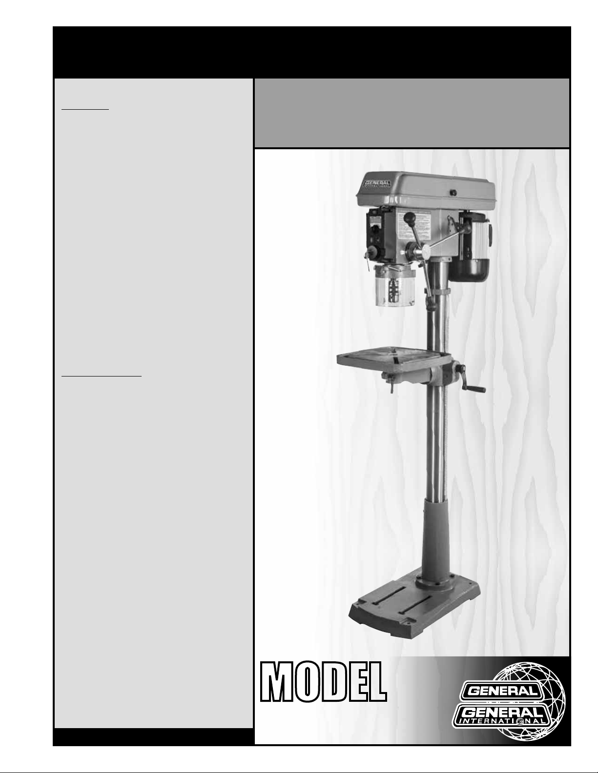
17″ DRILL PRESS
-
ELECTRONIC VARIABLE SPEED
MODEL
#
75-710
Page 2

GENERAL® INTERNATIONAL
8360 Champ-d’Eau, Montreal (Quebec) Canada H1P 1Y3
Telephone (514) 326-1161 • Fax (514) 326-5555 • www.general.ca
THANK YOU
for choosing this General® International model 75-710 drill
press. This drill press has been carefully tested and inspected before shipment and if properly
used and maintained, will provide you with years of reliable service. For your safety, as well
as to ensure optimum performance and trouble-free operation, and to get the most from
your investment, please take the time to read this manual before assembling, installing and
operating the unit.
The manual’s purpose is to familiarize you with the safe operation, basic function, and
features of this drill press as well as the set-up, maintenance and identification of its parts and
components. This manual is not intended as a substitute for formal woodworking/metalworking
instruction, nor to offer the user instruction in the craft of woodworking/metalworking. If you
are not sure about the safety of performing a certain operation or procedure, do not proceed
until you can confirm, from knowledgeable and qualified sources, that it is safe to do so.
Once you’ve read through these instructions, keep this manual handy for future reference.
DISCLAIMER: The information and specifications
in this manual pertain to the unit as it was supplied
from the factory at the time of printing. Because we
are committed to making constant improvements,
General® International reserves the right to make
changes to components, parts or features of this
unit as deemed necessary, without prior notice and
without obligation to install any such changes on
previously delivered units. Reasonable care is taken
at the factory to ensure that the specifications and
information in this manual corresponds with that of the
unit with which it was supplied. However, special orders
and “after factory” modifications may render some
or all information in this manual inapplicable to your
machine. Further, as several generations of this model
of drill press and several versions of this manual may
be in circulation, if you own an earlier or later version of
this unit, this manual may not depict your unit exactly. If
you have any doubts or questions contact your retailer
or our support line with the model and serial number of
your unit for clarification.
Page 3

GENERAL® INTERNATIONAL WARRANTY
All component parts of General® International and Excalibur by General International® products
are carefully inspected during all stages of production and each unit is thoroughly inspected upon
completion of assembly.
Limited Lifetime Warranty
Because of our commitment to quality and customer satisfaction, General® International agrees to
repair or replace any part or component which upon examination, proves to be defective in either
workmanship or material to the original purchaser for the life of the tool. However, the Limited Lifetime
Warranty does not cover any product used for professional or commercial production purposes nor
for industrial or educational applications. Such cases are covered by our Standard 2-year Limited
Warranty only. The Limited Lifetime Warranty is also subject to the “Conditions and Exceptions” as listed
below.
Standard 2-Year Limited Warranty
All products not covered by our lifetime warranty including products used in commercial, industrial
and educational applications are warranted for a period of 2 years (24 months) from the date of
purchase. General® International agrees to repair or replace any part or component which upon
examination, proves to be defective in either workmanship or material to the original purchaser during
this 2-year warranty period, subject to the “conditions and exceptions” as listed below.
To file a Claim
To file a claim under our Standard 2-year Limited Warranty or under our Limited Lifetime Warranty,
all defective parts, components or machinery must be returned freight or postage prepaid to
General® International, or to a nearby distributor, repair center or other location designated by
General® International. For further details call our service department at 1-888-949-1161 or your local
distributor for assistance when filing your claim.
Along with the return of the product being claimed for warranty, a copy of the original proof of purchase
and a “letter of claim” must be included (a warranty claim form can also be used and can be obtained,
upon request, from General® International or an authorized distributor) clearly stating the model and
serial number of the unit (if applicable) and including an explanation of the complaint or presumed
defect in material or workmanship.
CONDITIONS AND EXCEPTIONS:
This coverage is extended to the original purchaser only. Prior warranty registration is not required but
documented proof of purchase i.e. a copy of original sales invoice or receipt showing the date and
location of the purchase as well as the purchase price paid, must be provided at the time of claim.
Warranty does not include failures, breakage or defects deemed after inspection by
General® International to have been directly or indirectly caused by or resulting from; improper use,
or lack of or improper maintenance, misuse or abuse, negligence, accidents, damage in handling or
transport, or normal wear and tear of any generally considered consumable parts or components.
Repairs made without the written consent of General® International will void all warranty.
Page 4

TABLE OF CONTENTS
Rules for safe operation ..................................................................................................... 5
Electrical requirements ...................................................................................................... 6
Identification of main parts and components .................................................................. 7
Unpacking .......................................................................................................................... 8
Cleaning............................................................................................................................. 9
Placement within the shop ................................................................................................ 9
Assembly instructions ............................................................................................... 10 - 16
Installing the column on the base .................................................................................................................. 10
Installing the head stock on the column ................................................................................................ 10 - 11
Installing the table ..................................................................................................................................... 11 - 12
Installing the chuck guard............................................................................................................................... 13
Installing the downfeed handles .................................................................................................................... 13
Installing the chuck ................................................................................................................................... 13 - 14
Removing the chuck ........................................................................................................................................ 14
Installing a drill bit ............................................................................................................................................. 15
Basic adjustments and controls ............................................................................... 15 - 19
Connecting to a power source .......................................................................................................................15
On/Off power switch .........................................................................................................................................15
Adjusting the chuck guard height .................................................................................................................. 16
Adjusting the depth stop .................................................................................................................................. 16
Table swing adjustment ................................................................................................................................... 16
Pivoting the table .............................................................................................................................................. 17
Adjusting table height ...................................................................................................................................... 17
Table tilt adjustment .......................................................................................................................................... 17
Drill speed adjustment ..................................................................................................................................... 18
Guidelines for selecting speeds based on bit size and bit material .......................................................... 18
Spindle speed ranges ...................................................................................................................................... 18
Changing spindle speed range ..................................................................................................................... 19
Operating Instructions ..................................................................................................... 20
Checklist before starting .................................................................................................................................. 20
Drilling step-by-step .......................................................................................................................................... 20
Maintenance .................................................................................................................... 21
Belt replacement .............................................................................................................................................. 21
Lubrication ......................................................................................................................................................... 21
Recommended optional accessories ............................................................................. 21
Parts list & diagram .................................................................................................. 22 - 24
Contact information ........................................................................................................ 26
Page 5

RULES FOR SAFE OPERATION
To help ensure safe operation, please take a moment to learn the machine’s applications and limitations,
as well as potential hazards. General
harmless for any injury that may result from the improper use of it’s equipment.
1. Do not operate the drill press when tired, distracted, or under the effects of drugs, alcohol or any
medication that impairs reflexes or alertness.
2. The work area should be well lit, clean and free of
debris.
3. Keep children and visitors at a safe distance when
the drill press is in operation; do not permit them
to operate the drill press.
4. Childproof and tamper proof your shop and allmachinery with locks, master electrical switches
and switch keys, to prevent unauthorized or unsupervised use.
5. Stay alert! Give your work your undivided attention. Even a momentary distraction can lead to
serious injury.
6. Fine particulate dust is a carcinogen that can
be hazardous to health. Work in a well-ventilated
area and whenever possible use a dust collector
and wear eye, ear and respiratory protection devices.
7. Do not wear loose clothing, gloves, bracelets,
necklaces or other jewelry while the drill press is in
operation.
8. Be sure that adjusting wrenches, tools, drinks and
other clutter are removed from the machine and/
or the table surface before operating.
9. Keep hands well away from the drill bit and all
moving parts. Use a hold-down or clamp to secure the stock, and use a brush, not hands, to
clear away chips and dust.
10. Be sure that the drill bit is securely installed in
the chuck before operation.
11. Be sure the drill bit has gained full operating
speed before beginning to drill. Always use a
clean, properly sharpened bit. Dirty or dull bits
are unsafe and can lead to accidents. Use suit-
®
International disclaims any real or implied warranty and holds itself
able work piece support if the work piece does
not have a flat surface.
12. Do not push or force the bit into the stock. The drill
will perform better and more safely when working
at the rate feed for which it was designed.
13. Avoid working from awkward or off balance positions. Do not overreach and keep both feet on
floor.
14. Keep guards in place and in working order. If
a guard must be removed for maintenance or
cleaning be sure it is properly re-attached before
using the tool again.
15. Never leave the machine unattended while it is
running or with the power on.
16. Use of parts and accessories NOT recommended
by GENERAL® INTERNATIONAL may result in equipment malfunction or risk of injury.
17. Never stand on machinery. Serious injury could
result if the tool is tipped over or if the drill bit is
unintentionally contacted.
18. Always disconnect the tool from the power
source before servicing or changing accessories such as bits, or before performing any maintenance, cleaning, or if the machine will be left
unattended.
19. Make sure that the switch is in the “OFF” position before plugging in the power cord.
20. Make sure the tool is properly grounded. If
equipped with a 3-prong plug, it should be used
with a three-pole receptacle. Never remove the
third prong.
21. Do not use this drill press for other than its
intended use. If used for other purposes,
GENERAL® INTERNATIONAL disclaims any real implied warranty and holds itvself harmless for any
injury, which may result from that use.
5
Page 6

ELECTRICAL REQUIREMENTS
BEFORE CONNECTING THE MACHINE TO THE POWER SOURCE, VERIFY THAT THE VOLTAGE OF YOUR POWER
SUPPLY CORRESPONDS WITH THE VOLTAGE SPECIFIED ON THE MOTOR I.D. NAMEPLATE. A POWER SOURCE
WITH GREATER VOLTAGE THAN NEEDED CAN RESULT IN SERIOUS INJURY TO THE USER AS WELL AS DAMAGE
TO THE MACHINE. IF IN DOUBT, CONTACT A QUALIFIED ELECTRICIAN BEFORE CONNECTING TO THE POWER
SOURCE.
THIS TOOL IS FOR INDOOR USE ONLY. DO NOT EXPOSE TO RAIN OR USE IN WET OR DAMP LOCATIONS.
NOTE: IN THE EVENT OF A MALFUNCTION DO NOT OPEN OR ATTEMPT TO REPAIR THIS ELECTRONIC INVERTER.
CONTACT A LICENSED ELECTRICIAN OR QUALIFIED REPAIR PERSON TO INSPECT AND REPAIR THE INVERTER.
FAILURE TO COMPLY CAN LEAD TO SERIOUS PERSONAL INJURY INCLUDING ELECTROCUTION AND/OR DAMAGE
TO THE INVERTER AND THE MOTOR.
GROUNDING INSTRUCTIONS
In the event of an electrical malfunction or short circuit,
grounding reduces the risk of electric shock. The motor
of this machine is wired for 120 V single phase operation and is equipped with a 3-conductor cord and
a 3-prong grounding plug A to fit a grounded type
receptacle B. Do not remove the 3rd prong (grounding pin) to make it fit into an old 2-hole wall socket or
extension cord. If an adaptor plug is used C, it must be
attached to the metal screw of the receptacle.
Note: The use of an adaptor plug is illegal in some areas. Check your local codes. If you have any doubts
or if the supplied plug does not correspond to your
electrical outlet, consult a qualified electrician before proceeding.
A
B
C
CIRCUIT CAPACITY
Make sure that the wires in your circuit are capable of handling the amperage draw from your machine, as well
as any other machines that could be operating on the same circuit. If you are unsure, consult a qualified electrician. If the circuit breaker trips or the fuse blows regularly, your machine may be operating on a circuit that is
close to its amperage draw capacity. However, if an unusual amperage draw does not exist and a power failure
still occurs, contact a qualified technician or our service department.
EXTENSION CORDS
If you find it necessary to use an extension cord with your machine, use only 3-wire extension cords that have
3-prong grounding plug and a matching 3-pole receptacle that accepts the tool’s plug. Repair or replace a damaged extension cord or plug immediately.
Make sure the cord rating is suitable for the amperage listed on the motor I.D. plate. An undersized cord will cause
a drop in line voltage resulting in loss of power and overheating. The accompanying chart shows the correct size
extension cord to be used based on cord length and motor I.D. plate amp rating. If in doubt, use the next heavier
gauge. The smaller the number, the heavier the gauge.
TABLE - MINIMUM GAUGE FOR CORD
EXTENSION CORD LENGTH
AMPERES 50 feet 100 feet 200 feet 300 feet
< 5
6 to 10
10 to 12
12 to 16
*NR = Not Recommended
18 16 16 14
18 16 14 12
16 16 14 12
14 12 *NR *NR
6
Page 7
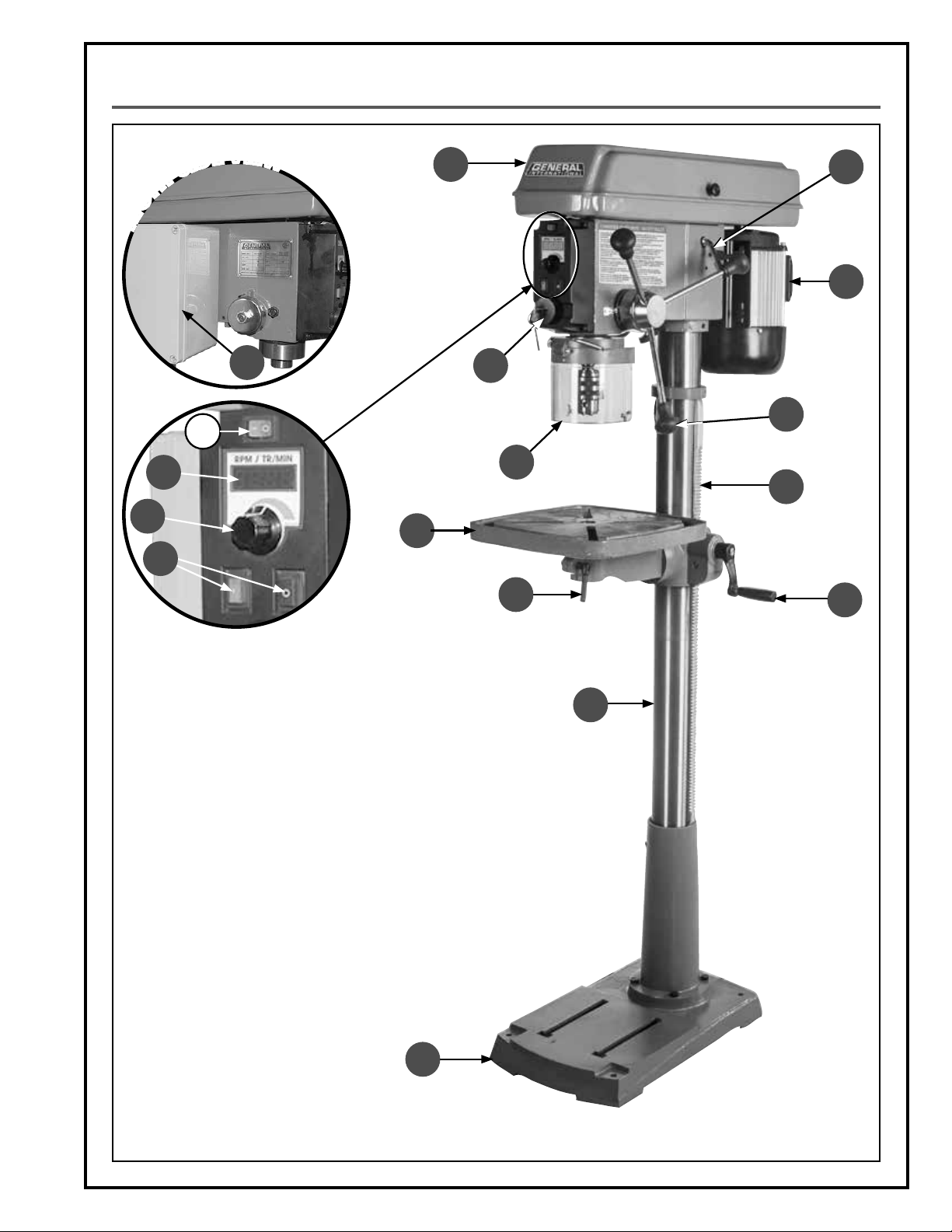
IDENTIFICATION OF MAIN PARTS AND COMPONENTS
V
I
E
W
L
M
N
R
G
I
H
E
D
I
S
T
K
J
I
H
D
G
G
A. BASE
B. COLUMN
C. TABLE PIVOT LOCK LEVER
D. TABLE
E. FLIP-UP CHUCK GUARD
F. MUSHROOM STYLE STOP WITH LOCK-OUT KEY
G. MAIN ON/OFF SWITCH
H. VARIABLE SPEED CONTROLLER
I. DIGITAL SPEED DISPLAY
J. LASER SWITCH
K. ELECTRONIC INVERTER
L. PULLEY COVER
M. BELT TENSION LEVER
N. MOTOR
O. FEED HANDLE
P. RACK
Q. TABLE CRANK HANDLE
A
F
O
E
P
C
Q
B
7
Page 8
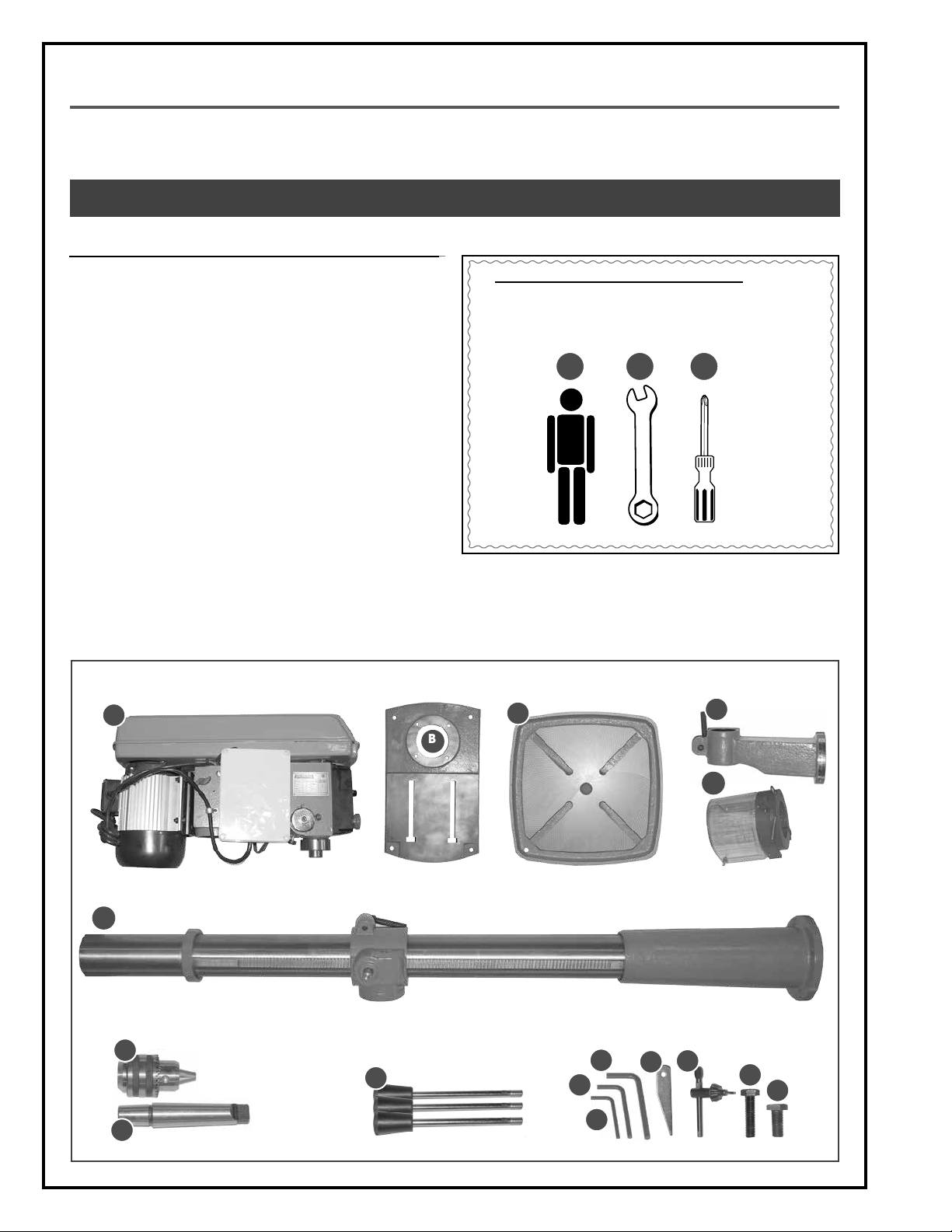
UNPACKING
Carefully unpack and remove the unit and its components from the box and check for missing or damaged items
as per the list of contents below.
NOTE: PLEASE REPORT ANY DAMAGED OR MISSING ITEMS TO YOUR GENERAL® INTERNATIONAL DISTRIBUTOR IMMEDIATELY.
LIST OF CONTENTS QTY
A. HEAD STOCK ............................................................................ 1
B. BASE ......................................................................................... 1
C. TABLE ........................................................................................ 1
D. TABLE SUPPORT ARM ............................................................... 1
E. CHUCK GUARD ....................................................................... 1
F. COLUMN .................................................................................. 1
G. CHUCK ..................................................................................... 1
H. ARBOR...................................................................................... 1
I. DOWNFEED HANDLE ............................................................... 3
J. 3 MM ALLEN KEY .................................................................... 1
K. 4 MM ALLEN KEY ..................................................................... 1
L. 5 MM ALLEN KEY ..................................................................... 1
M. DRIFT KEY ................................................................................. 1
N. CHUCK KEY .............................................................................. 1
O. BASE BOLT ................................................................................ 4
P. ARM BOLT ................................................................................ 1
ADDITIONAL REQUIREMENTS FOR SET UP
A. EXTRA PERSON FOR HELP WITH LIFTING
B. 9, 16 & 24 MM OPEN WRENCHES
C. PHILLIPS SCREWDRIVER
A B
C
A
B
F
G
I
H
C
L
K
J
M
D
E
N
O
P
8
Page 9

CLEANING
The protective coating on the machine prevents rust
from forming during shipping and storage. Remove it
by rubbing with a rag dipped in kerosene, mineral spirits or paint thinner. (Dispose of potentially flammable
solvent-soaked rags according to manufacturer’s safety recommendations).
A putty knife, held flat to avoid scratching the surface,
may also be used to scrape off the coating followed
by clean-up with solvent. Avoid rubbing the machine's
painted surfaces, as many solvent-based products will
remove paint.
To prevent rust, apply a light coating of paste wax or
use regular applications of any after-market surface
protectant or rust inhibitor.
PLACEMENT WITHIN THE SHOP / SAFETY ZONE
THIS DRILL PRESS MODEL 75-710 IS HEAVY. DO NOT OVER-EXERT. A HOIST OR FORKLIFT WITH STRAPS SHOULD BE
USED TO LIFT THIS MACHINE. TO LIMIT THE RISK OF SERIOUS INJURY OR DAMAGE TO THE MACHINE, ANY EQUIPMENT
USED TO LIFT THIS MACHINE SHOULD HAVE A RATED CAPACITY IN EXCESS OF THE WEIGHT OF THE MACHINE.
PLACEMENT WITHIN THE SHOP
This machine should be installed and operated only
on a solid, flat and stable floor that is able to support
the weight of the machine 136 lbs (73 kg).
Using the dimensions shown as a guideline, plan for
placement within your shop that will allow the operator
to work unencumbered and unobstructed by foot traffic (either passing shop visitors or other shop workers)
or other tools or machinery.
ESTABLISHING A SAFETY ZONE
For shops with frequent visitors or multiple operators,
it is advisable to establish a safety zone around shop
machinery.
A clearly defined “no-go” zone on the floor around
each machine can help avoid accidents that could
cause injury to either the operator or the shop visitor.
It is advisable to take a few moments to either paint
(using non-slip paint) or using tape, define on the floor
the limits or perimeter of each machines safety zone.
Take steps to ensure that all operators and shop visitors are aware that these areas are off limits whenever
a machine is running for everyone but the individual
operating the unit.
13
¼
23 ½"
"
64 ½"
¼"
0
1
2
"
2
9
Page 10

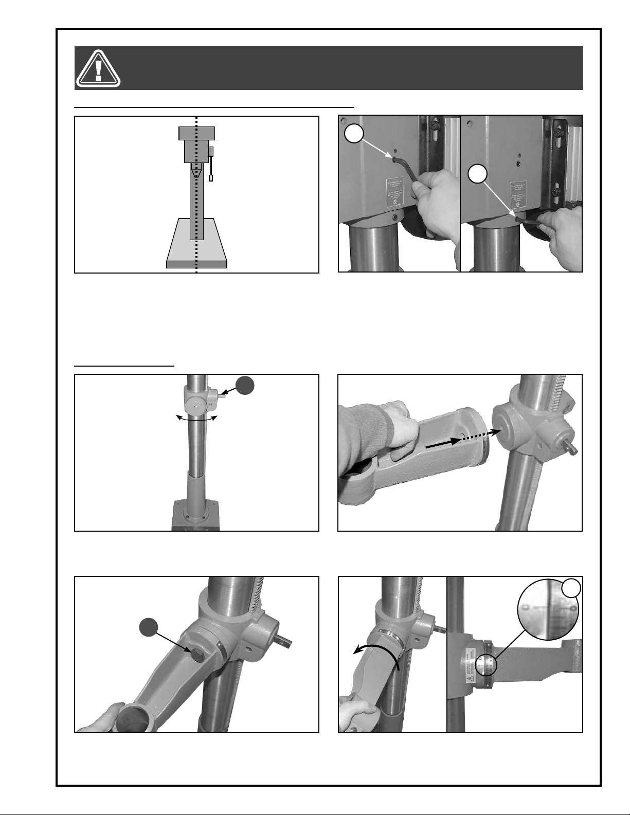
ASSEMBLY INSTRUCTIONS
BEFORE ASSEMBLING, MAKE SURE THAT THE SWITCH IS IN THE “OFF” POSITION AND THAT THE POWER CORD IS
UNPLUGGED. DO NOT PLUG IN OR TURN ON THE MACHINE UNTIL YOU HAVE COMPLETED THE ASSEMBLY AND
INSTALLATION STEPS DESCRIBED IN THIS SECTION OF THE MANUAL.
INSTALLING THE COLUMN ON THE BASE
1. Set the base on a flat and stable surface, and then
install the column on the base.
A
3. Tighten the four bolts by hand A few turns.
INSTALLING THE HEAD STOCK ON THE COLUMN
THE HEAD STOCK IS HEAVY. DO NOT OVER-EXERT. THE HELP OF AN ASSISTANT WILL BE NEEDED FOR THE FOLLOWING
STEP. DO NOT GRIP THE HEAD STOCK BY THE PULLEY COVER WHEN LIFTING.
2. Align the mounting holes in the column with the
corresponding holes in the base.
4. Then secure the bolts using a 16 mm wrench.
1. Lift the head stock and place its opening above
the column.
10
2. Slide the head stock opening onto the column.
Page 11
BEFORE ASSEMBLING, MAKE SURE THAT THE SWITCH IS IN THE “OFF” POSITION AND THAT THE POWER CORD IS
UNPLUGGED. DO NOT PLUG IN OR TURN ON THE MACHINE UNTIL YOU HAVE COMPLETED THE ASSEMBLY AND
INSTALLATION STEPS DESCRIBED IN THIS SECTION OF THE MANUAL.
INSTALLING THE HEAD STOCK ON THE COLUMN (CONTINUED)
A
B
3. Center the head stock with the column and the
base.
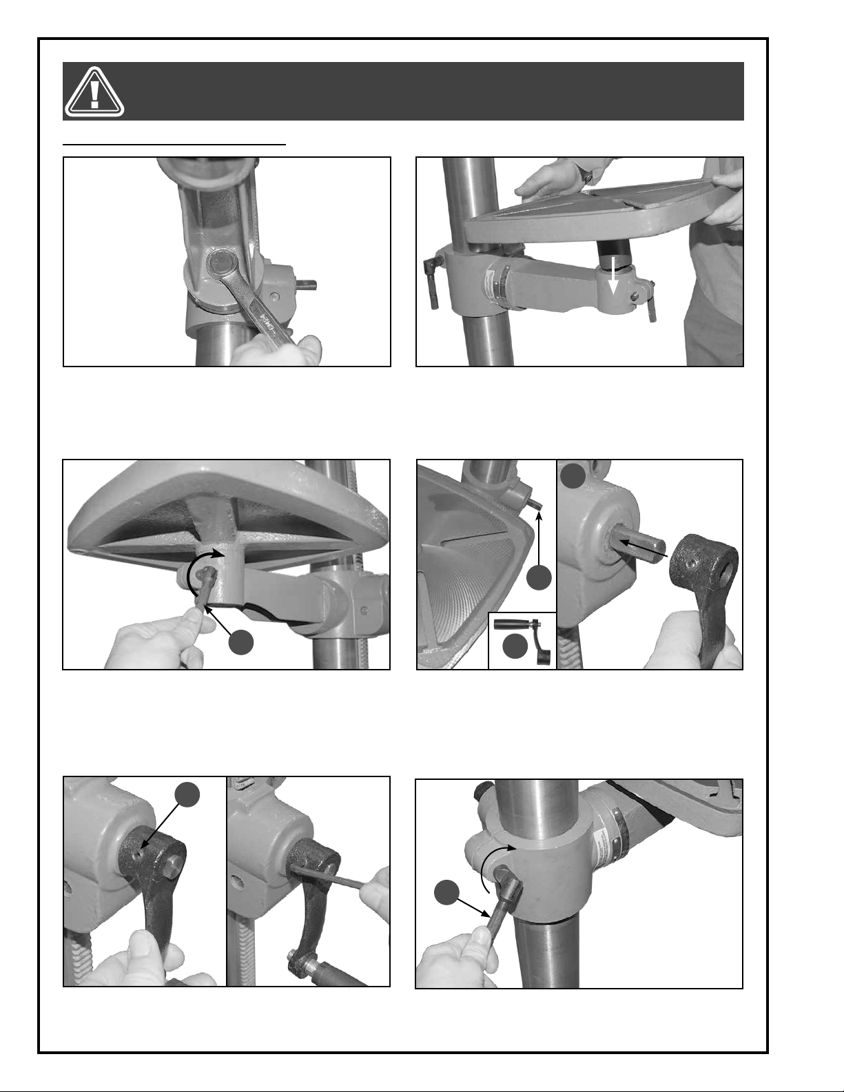
INSTALLING THE TABLE
C
1. Make sure that arbor C is to the right and the table
bracket is centered on the column. Turn the bracket if needed as shown.
4. Secure the head stock to the column by tightening screws A & B using a 5 mm Allen key.
2. Hold the arm against the bracket aligning the
mounting holes as shown.
E
D
3. Tighten bolt D hand tight for now. 4. Turn the arm counterclockwise until the zero point
of the table bracket and the arm are aligned as
shown E.
11
Page 12
BEFORE ASSEMBLING, MAKE SURE THAT THE SWITCH IS IN THE “OFF” POSITION AND THAT THE POWER CORD IS
UNPLUGGED. DO NOT PLUG IN OR TURN ON THE MACHINE UNTIL YOU HAVE COMPLETED THE ASSEMBLY AND
INSTALLATION STEPS DESCRIBED IN THIS SECTION OF THE MANUAL.
INSTALLING THE TABLE (CONTINUED)
5. Tighten the arm's mounting bolt using a 24 mm
wrench.
A
7. Lock the table in place by turning lever A clock-
wise.
6. Insert the table into the arm mount as shown.
D
C
B
8. Slide handle B onto the arbor C as shown D.
E
9. Tighten the set screw E using a 4 mm Allen key.
12
F
10. Lock the table in position by tightening the lever F
as shown.
Page 13

BEFORE ASSEMBLING, MAKE SURE THAT THE SWITCH IS IN THE “OFF” POSITION AND THAT THE POWER CORD IS
UNPLUGGED. DO NOT PLUG IN OR TURN ON THE MACHINE UNTIL YOU HAVE COMPLETED THE ASSEMBLY AND
INSTALLATION STEPS DESCRIBED IN THIS SECTION OF THE MANUAL.
INSTALLING THE CHUCK GUARD
A
1. Slide the chuck guard onto its support as shown A.
INSTALLING THE DOWNFEED HANDLES
B
mounting holes located in the support B.
INSTALLING THE CHUCK
2. Tighten the chuck guard using a phillips screw-
driver.
2. Tighten each handle using a 9 mm wrench.1. Thread the three downfeed handles into their
1. Lift the chuck guard as shown.
2. Clean inside the chuck with a dry cloth until all
grease or lubricant is removed.
13
Page 14

BEFORE ASSEMBLING, MAKE SURE THAT THE SWITCH IS IN THE “OFF” POSITION AND THAT THE POWER CORD IS
UNPLUGGED. DO NOT PLUG IN OR TURN ON THE MACHINE UNTIL YOU HAVE COMPLETED THE ASSEMBLY AND
INSTALLATION STEPS DESCRIBED IN THIS SECTION OF THE MANUAL.
INSTALLING THE CHUCK (CONTINUED)
3. Fit the arbor into the chuck as shown.
5. Slide the arbor into the quill assembly as shown.
REMOVING THE CHUCK
A
4. Make sure the arbor is inserted all the way into the
chuck.
6. Using the feed handles, lower the chuck against
a piece of wood on the table to pressfit it into the
quill.
B
1. Using feed handle, lower the quill assembly A. In-
sert the drift key B all the way into the quill assembly C.
14
C
D
2. While holding onto the chuck, tap gently on the
key with a hammer or rubber mallet to loosen and
remove the arbor and chuck.
Note: It may be necessary to rotate the quill in order to be
able to get the tool all the way through D.
Page 15

BEFORE ASSEMBLING, MAKE SURE THAT THE SWITCH IS IN THE “OFF” POSITION AND THAT THE POWER CORD IS
UNPLUGGED. DO NOT PLUG IN OR TURN ON THE MACHINE UNTIL YOU HAVE COMPLETED THE ASSEMBLY AND
INSTALLATION STEPS DESCRIBED IN THIS SECTION OF THE MANUAL.
INSTALLING A DRILL BIT
A
1. Open the chuck by turning the key A counter-
clockwise until you can insert a drill bit B.
B
2. Secure the drill bit in the chuck by turning the key
clockwise.
BASIC ADJUSTMENTS & CONTROLS
TO REDUCE THE RISK OF SHOCK OR FIRE DO NOT OPERATE THE UNIT WITH A DAMAGED POWER CORD OR PLUG. REPLACE DAMAGED CORD OR PLUG IMMEDIATELY. TO AVOID UNEXPECTED OR UNINTENTIONAL START-UP, MAKE SURE
THE POWER SWITCH IS IN THE OFF POSITION BEFORE CONNECTING TO A POWER SOURCE.
CONNECTING TO A POWER SOURCE
Once the assembly steps have been completed, plug
the power cord into an appropriate outlet.
Refer back to the section entitled “Electrical Require
ments” and make sure all requirements and grounding
instructions are followed.
When operations have been completed unplug the
machine from the power source.
-
SWITCH OFF
TO AVOID UNEXPECTED OR UNINTENTIONAL
START-UP, MAKE SURE THAT THE POWER SWITCH
IS IN THE OFF POSITION BEFORE CONNECTING
TO A POWER SOURCE.
ON/OFF POWER SWITCH
This machine is equipped with an electronic system designed to protect the unit and the user from power surges,
power outages or unintentional start-up.
The switch assembly is equipped with a “start” button A, a “stop” button B and a emergency stop button with lockout key C. Once this button has been pressed, the machine can only be started by inserting the key to release
the stop button C.
The laser pointer is controlled using switch D. To turn on the laser pointer, press "I"; to turn off the laser press "O".
D
LASER POINTER SWITCH
A
POWER ON/OFF
C
B
EMERGENCY STOP BUTTON
15
Page 16

MAKE SURE THE MACHINE HAS BEEN TURNED OFF AND UNPLUGGED FROM THE POWER SOURCE BEFORE PERFORMING ANY MAINTENANCE OR ADJUSTMENTS.
ADJUSTING THE CHUCK GUARD HEIGHT
A
1. Loosen the wing nuts A.
2. Position the shield at the desired height, then re-
tighten the wing nuts.
ADJUSTING THE DEPTH STOP
This drill is equipped with an adjustable depth stop to allow repetitive drilling to a set depth. To set the depth stop:
B
C
1. Loosen knob B counterclockwise as shown.
TABLE SWING ADJUSTMENT
2. Turn the depth stop to the desired drilling depth C,
then retighten the knob.
1. Loosen the column lock handle as shown.
16
2. Swing the table arm bracket and the table to the
desired position, then retighten the column lock
handle.
Note: When working with taller work pieces swing the table 180° out of the way and use the base as a table.
Page 17

MAKE SURE THE MACHINE HAS BEEN TURNED OFF AND UNPLUGGED FROM THE POWER SOURCE BEFORE PERFORMING ANY MAINTENANCE OR ADJUSTMENTS.
PIVOTING THE TABLE
1. Loosen the pivot lock handle as shown.
ADJUSTING TABLE HEIGHT
1. Loosen the column lock handle as shown.
TABLE TILT ADJUSTMENT
2. Turn the table to the desired position, and then re-
tighten the pivot lock handle.
2. Turn the crank handle as shown until the table is at
the desired height, then retighten the column lock
handle.
A
1. Loosen nut A
2. Tilt the table to the desired angle, and then retight-
en the nut A.
17
Page 18

MAKE SURE THE MACHINE HAS BEEN TURNED OFF AND UNPLUGGED FROM THE POWER SOURCE BEFORE PERFORMING ANY MAINTENANCE OR ADJUSTMENTS.
DRILL SPEED ADJUSTMENT
The spindle speed ranges from 120 to 480 rpm, 280 to
1200 rpm and from 740 to 3200 rpm, depending on the
positionning of the drive belt on the pulleys.
Note: Refer to the reference chart below for speed selection, based on bit size and workpiece material.
The spindle speed control knob is located on the control box, just above the on/off switch.
- Turn the knob A clockwise to increase the spindle
speed.
- Turn the knob A counterclockwise to decrease the
spindle speed.
The spindle speed will be indicated on the digital
speed display .
GUIDELINES FOR SELECTING SPEEDS BASED ON BIT SIZE AND BIT MATERIAL
A
BIT MATERIAL
CAST STEEL TOOL STEEL CAST IRON MILD STEEL
DOWNFEED SPEED
DRILL BIT DIAMETER SPEED (rpm)
1/16" (2 MM) 1910 - 2445 2865 - 3665 3820 - 4890 4775 - 6110 9550 -12 225
1/8" (3 MM) 1220 - 1275 1835 - 1910 2445 - 2545 3055 - 3185 6110 - 6365
3/16" (5 MM) 765 - 815 1145 - 1220 1530 - 1630 1910 - 2035 3820 - 4075
1/4" (6 MM) 610 915 - 955 1220 - 1275 1530 - 1590 3055 - 3180
5/16" (8 MM) 480 - 490 715 - 735 955 - 980 1195 - 1220 2390 - 2445
3/8" (10 MM) 380 - 405 570 - 610 765 - 815 955 - 1020 1910 - 2035
7/16" (11MM) 350 520 - 525 700 870 1740 - 1745
1/2" (13 MM) 300 - 305 440 - 460 590 - 610 735 -765 1470 - 1530
5/8" (16 MM) 240 - 245 360 - 365 480 - 490 600 - 610 1200 - 1220
3/4" (19MM) 190 - 205 285 - 305 380 - 405 480 - 510 955 - 1200
40 pi/min 60 pi/min 80 pi/min 100 pi/min 200 pi/min
ALUMINUM
COPER
SPINDLE SPEED RANGES
120 - 480 rpm
280 - 1200 rpm
740 - 3200 rpm
18
Page 19

MAKE SURE THE MACHINE HAS BEEN TURNED OFF AND UNPLUGGED FROM THE POWER SOURCE BEFORE PERFORMING ANY MAINTENANCE OR ADJUSTMENTS.
CHANGING SPINDLE SPEED RANGE
A B
1. Unplug the machine, then unlock the motor by
loosening the two lock knobs A & B located on
either side of the headstock.
C
2. Turn the belt tension lever clockwise to loosen the
drive belt, C.
3. Open the cover pulley, then position the drive belt
on the pulleys based on the desired speed range.
5. Turn the belt tension lever counterclockwise to
tighten the belts, then while holding the tension lever, retighten the two lock knobs located on either
side of the head stock.
4. Position the second belt on the pulleys based on
the desired speed range.
6. Close the cover pulley before starting the machine.
19
Page 20

OPERATING INSTRUCTIONS
CHECKLIST BEFORE STARTING
VERIFY ALL CHECK POINTS BEFORE STARTING. FAILURE TO COMPLY CAN RESULT IN SERIOUS INJURIES.
• Make sure the pulley cover is closed.
• Check that the chuck is installed properly.
• Make sure the chuck guard is securely installed and closed properly.
• When turning the machine “ON” be aware that the shaft will rotate freely.
• When the drill press is running check to see if it runs without vibration or shaking.
• Make sure the table bracket moves up and down smoothly.
• Make sure the spindle shaft turns smoothly.
DRILLING STEP-BY-STEP
1. Lift the chuck guard as shown and install a drill bit
suitable for the type of material to drill.
3. Secure the workpiece in a vise (optional).
B
2. Flip the chuck guard down in place as shown.
A
4. For precision drilling use the laser pointer A to lo-
cate the drilling point on the workpiece.
5. Press "I" to turn on the machine and adjust the
speed by turning the knob B until the digital display indicates the speed desired.
Note: Make sure the emergency stop button is released.
20
6. Use the downfeed handles to lower the bit into the
workpiece.
Page 21
MAKE SURE THE MACHINE HAS BEEN TURNED OFF AND UNPLUGGED FROM THE POWER SOURCE BEFORE PERFORMING ANY MAINTENANCE OR ADJUSTMENTS.
MAINTENANCE
BELT REPLACEMENT
Inspect the belts afler every 100 hours of use. Belts that show visible signs of wear such as cracks or fraying at the
edges should be replaced immediately.
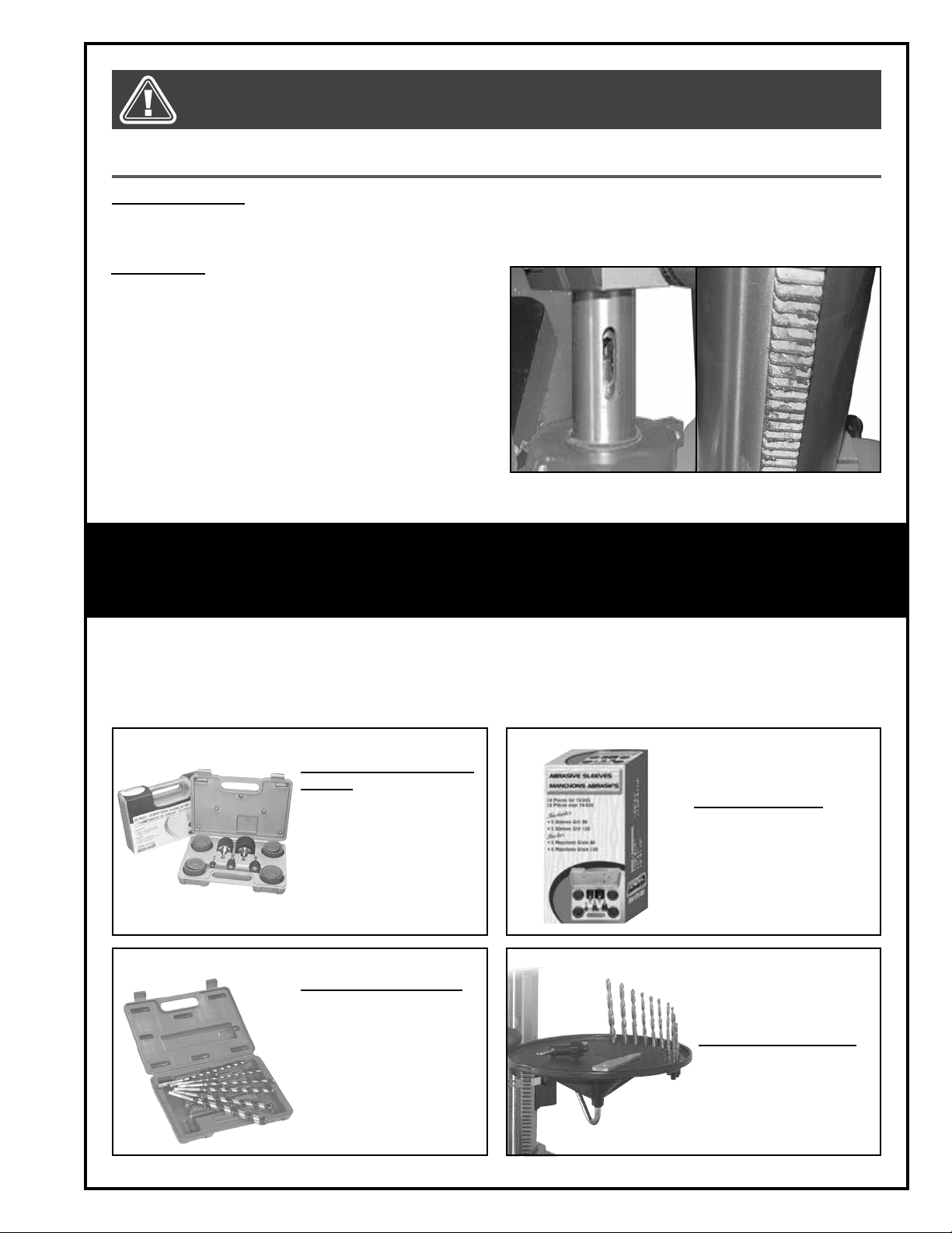
LUBRICATION
Periodically lubricate all sliding or moving parts including the column, rack and the quill shown (use any all
purpose grease, available at any hardware store).
Note: Bearings in the quill and the V-belt pulleys are sealed,
permanently lubricated and should require no further maintenance.
RECOMMENDED OPTIONAL ACCESSORIES
We offer a large variety of products to increase convenience, productivity, accuracy and safety when using
your saw. Here’s a small sampling of optional accessories available from your local General International
dealer.
For more information about our products, please visit our website at www.general.ca
Item #70-025
25 PIECE DRUM SANDING KIT
Turn your drill press into a
mini drum sander. 5 different sized drums: 1/2”,
3/4”, 1”, 1-1/2” & 2” plus 2
sets of 80 grit and 2 sets of
120 grit, sanding sleeves
for each.
Item #70-105
9” AUGER DRILL BIT SET
Heavy duty carbon steel.
Heat treated and precision sharpened for quick,
accurate and effortless
cuts. Includes 6 bits -sizes:
1/4”, 5/16”, 3/8”, 1/2”,5/8”,
3/4” with 3/8” shank, in a
convenient carrying case.
Item #70-030
ABRASIVE SLEEVES
10 piece replacement
abrasive sleeve set for
70-025. Includes 5 (one
of each size) 80 & 120 grit
sanding sleeves.
Item #70-125
DRILL PRESS TOOL TRAY
Can be installed on most
drill press columns. Made
with a metal swivel rod.
21
Page 22

DIAGRAM
75-710
22
Page 23

PARTS LIST
75-710
IMPORTANT: When ordering replacement parts, always give the model number, serial number of the
machine and part number. Also a brief description of each item and quantity desired.
PART # REFERENCE DESCRIPTION SPECIFICATION QTY
75710-01 16101001B BASE 1
75710-02 16201002 SUPPPORT COLUMN 1
75710-03 SET SCREW M10 X 12 3
75710-04 HEX HEAD BOLT M10 X 30 4
75710-05 16101010 RACK 1
75710-06 16201003 COLUMN 1
75710-07 SET SCREW M6 X 10 1
75710-08 16201011E COLLAR 1
75710-09 16101007A PIN 1
75710-10 16101006 HELICAL GEAR 1
75710-11 16101008 WORM GEAR 1
75710-12 SET SCREW M8 X 10 1
75710-13 13201009B HANDLE BRACKET 1
75710-14 13201009B-2 HANDLE 1
75710-15 SET SCREW M16 X 35 1
75710-16 16101013A LOCK HANDLE 1
75710-17 16201004 TABLE BRACKET 1
75710-18 16201005 TABLE ARM 1
75710-19 16201014D TABLE 1
75710-20 16101012A LOCK HANDLE 1
75710-21 20104011 KNOB 3
75710-22 16104005A ROD 3
75710-23 16104001 HANDLE BRACKET 1
75710-24 PIN 5 X 16 1
75710-25 16104003 DEPTH STOP RING 1
75710-26 16104004 LOCK BLOCK 1
75710-27 13102005B DEPTH LOCK SCREW 1
75710-28 16104002 PINION SHAFT 1
75710-29 16103005 NYLOCK NUT 1
75710-30 16103004 RETENTION RING 1
75710-31 16103003 WASHER 1
75710-32 BEARING 6203 1
75710-33 16203006 QUILL GASKET 1
75710-34 16203002 QUILL ASSEMBLY 1
75710-35 16103008 DRIFT KEY 1
75710-36 BEARING 1
75710-37 16203001A SPINDLE 1
75710-38 20103007 ARBOR 1
75710-39 16103009G CHUCK 1
75710-40 16103009G-1 CHUCK KEY 1
75710-41 20108002 CHUCK GUARD (ITEM #70115C) 75 MM 1
75710-42 13302026 LASER POINTER 2
75710-43 SET SCREW M6 X 8 2
75710-44 16104010 STOP PIN 1
75710-45 PIN 6 X 25 2
75710-46 RETENTION RING 1
75710-47 16202004 TENSION LEVER 1
75710-48 13102005B LOCK KNOB 2
75710-49 16202003 SLIDING ROD 1
75710-50 16202001U HEAD STOCK 1
75710-51 16102006 TENSION BLOCK 1
75710-52 HEX HEAD BOLT M8 X 16 1
75710-53 16202002 SLIDING ROD 1
75710-54 HEX HEAD BOLT M8 X 25 4
75710-55 WASHER 8
75710-56 16102007C MOTOR PLATE 1
75710-57 LOCK WASHER 12 2
23
Page 24

PARTS LIST
75-710
IMPORTANT: When ordering replacement parts, always give the model number, serial number of the
machine and part number. Also a brief description of each item and quantity desired.
PART # REFERENCE DESCRIPTION SPECIFICATION QTY
75710-58 NUT M12 2
75710-59 NUT M8 4
75710-60 YSL9014H MOTOR 1
75710-61 KEY 8 X 45 1
75710-62 HEX HEAD BOLT M8 X 10 1
75710-63 16205005S MOTOR PULLEY 1
75710-64 16205010 V-BELT 12.5 X 710 1
75710-65 16102014A CORD CLAMP 1
75710-66 SCREW M5 X 10 1
75710-67 WASHER 4
75710-68 SCREW M6 X 12 4
75710-69 16205007 CENTRAL SHAFT 1
75710-70 16205006F CENTRAL PULLEY 1
75710-71 BEARING 6202 2
75710-72 13205010 KNOB 1
75710-73 16205000 PULLEY COVER 1
75710-74 SCREW M5 X 12 1
75710-75 162050011 V BELT 12.5 X 765 1
75710-76 SCREW M3 X 6 1
75710-77 16205013 SPEED SENSOR TAB 1
75710-78 16102025 NUT 1
75710-79 16205009J CHUCK PULLEY 1
75710-80 16202022 SHAFT 1
75710-81 16202024 RETENTION RING 2
75710-82 BEARING 60205 2
75710-83 16202023A SPACER 1
75710-84 NUT M12 2
75710-85 16104008 CAP SPRING 1
75710-86 16104009 SPRING 1
75710-87 16104007A SPRING 1
75710-88 16104006A SLEEVE 1
75710-89 13105009 RUBBER WASHER 4
75710-90 16102021 NYLOCK NUT 1
75710-91 NUT M10 1
75710-92 16202008J SWITCH BOX 1
75710-93 CAP SCREW ST2.9X6.5 2
75710-94 DQ010002200 DIGITAL SPEED DISPLAY 1
75710-95 CAP SCREW M5 X 6 2
75710-96 SPROCKET WASHER 2
75710-97 SCREW M5 X 16 4
75710-98 S16G05003-1 STOP BUTTON 1
75710-99 EMERGENCY STOP BUTTON WITH LOCK-OUT KEY 1
75710-100 S16G05003-2 START BUTTON 1
75710-101 S1605011 SPEED CONTROL KNOB 1
75710-102 S1605010 POTENTIOMETER 1
75710-103 KCD1 LASER POINTER SWITCH 1
75710-104 NYLOCK NUT M4 2
75710-105 16205012 SENSOR PLATE 1
75710-106 DQ014001100-4 SENSOR 1
75710-107 CAP SCREW M2.5X5 2
75710-108 SCREW M4 X 20 2
75710-109 16205014 INVERTER BOX 1
75710-110 VFD007M11A INVERTER 1
75710-111 16205015 INVERTER COVER 1
75710-112 DLCKEE3S16 CORD W/PLUG 1
75710-113 ALLEN KEY 3 MM 1
75710-114 ALLEN KEY 4 MM 1
75710-115 ALLEN KEY 5 MM 1
24
Page 25

NOTES
Page 26

8360 Champ-d’Eau, Montreal (Quebec) Canada H1P 1Y3
Tel.: (514) 326-1161
Fax: (514) 326-5565 - Parts & Service / (514) 326-5555 - Order Desk
orderdesk@general.ca
www.general.ca
Follow us:
 Loading...