

Page 1
Independently adjustable left and right
fences.
Sturdy 32” x 24” tabletop made of heavy
1” melamine surface MDF.
Includes 12” x 9” router insert plate, starting pin, and 2 removable insert rings
(permitting 3 different diameters: 1 1/4”,
2 5/8”, and 3 7/8”).
Two convenient front access storage
shelves.
Graduated scale and adjustment knobs
for precision fence setting.
Movable switch with outlet for convenient
operation.
OVERALL DIMENSIONS
32” x 24” x 39”(812 x 609 x 990 mm)
T
ABLE SIZE
32” x 24” (812 x 609 mm)
T
ABLE HEIGHT
36” (914 mm)
FENCE SIZE (EA
CH)
3” x 16” x 1” (76 x 406 x 25 mm)
MAXIMUM FENCE
TRAVEL
6 1/2” (165 mm)
DUST OUTLET
2 1/2” (67 mm)
DIST
ANCE BETWEEN T-SLOT
& SPINDLE CENTER
6” (152 mm)
T SLO
T DIMENSIONS
3/4” x 3/8” (19 x 9.5 mm)
ROUTER INSER
T PLATE
12” x 9”
T
ABLE INSERT OPENINGS
1-1/4”, 2-5/8”, & 3-7/8” (32, 67 & 98mm)
Dia.
WEIGHT
61 lbs (28 kg)
© Copyright General International 06/2007
REVISION 2 - JUNE 4/07
Page 2

THANK YOU
for choosing this General® International model 40-040 router table.
This router table has been carefully tested and inspected before shipment and if properly used
and maintained, will provide you with years of reliable service. To ensure optimum performance and trouble-free operation, and to get the most from your investment, please take the
time to read this manual before assembling, installing and operating the unit.
The manual’s purpose is to familiarize you with the safe operation, basic function, and features
of this router table as well as the set-up, maintenance and identification of its
parts and components. This manual is not intended as a substitute for formal woodworking
instruction, nor to offer the user instruction in the craft of woodworking. If you are not sure about
the safety of performing a certain operation or procedure, do not proceed until you can
confirm, from knowledgeable and qualified sources, that it is safe to do so.
Once you’ve read through these instructions, keep this manual handy for future reference.
All component parts of General® International machinery are carefully tested and inspected during all stages of
production, and each machine is thoroughly inspected upon completion of assembly. Because of our commitment to quality and customer satisfaction, General® International agrees to repair or replace, within a period of 24
months from date of purchase, any genuine part or parts which, upon examination, prove to be defective in workmanship or material. In order to obtain this warranty, all defective parts must be returned freight pre-paid to
General® International Mfg. Co., Ltd. Repairs attempted without our written authorization will void this warranty.
GENERAL ® INTERNATIONAL WARRANTY
Disclaimer:
The information and specifications in this manual pertain to
the unit as it was supplied from the factory at the time of printing.
Because we are committed to making constant improvements, General
International reserves the right to make changes to components, parts
or features of this unit as deemed necessary, without prior notice and
without obligation to install any such changes on previously delivered
units. Reasonable care is taken at the factory to ensure that the specifications and information in this manual corresponds with that of the unit
with which it was supplied. However, special orders and “after factory”
modifications may render some or all information in this manual
inapplicable to your table. Further, as several generations of this model
of router table and several versions of this manual may be in circulation,
if you own an earlier or later version of this unit, this manual may not
depict your machine exactly. If you have any doubts or questions contact your retailer or our support line with the model and serial number of
your unit for clarification.
GENERAL® INTERNATIONAL
8360 Champ-d’Eau, Montreal (Quebec) Canada H1P 1Y3
Telephone (514) 326-1161 • Fax (514) 326-5555 • www.general.ca
Page 3

Rules for Safe Operation
To help ensure safe operation, please take a moment to learn the machine’s applications and limitations, as well as potential hazards. General® International disclaims any real or implied warranty and
holds itself harmless for any injury that may result from improper use of its equipment.
1. Make sure that the operator has been properly trained
and has read and understands the Owner’s Manual
before operating any machinery.
2. Be sure to read, understand,and follow all instructions,
warnings, and safety guidelines supplied with your
router.
3. Keep the work area well lit, clean, and free of debris.
4. STAY ALERT! Give your work you undivided attention.
Even a momentary distraction can lead to serious
injury.
5. Do not wear loose clothing, gloves, bracelets, neck-
laces, or other protection devices. Wear protective
hair covering to contain long hair and wear non-slip
footwear.
6. Keep hands and other body parts well away from bits
or cutting tools. When working close to the cutting tool,
always use a feather board or push-stick to hold or
guide the workpiece. Do not clear chips and sawdust
away with hands; use a brush.
7. Fine particulate dust is a carcinogen that can be haz-
ardous to health. Always work in a well ventilated area
and whenever possible use a dust collector to minimize health hazards.
8. Be sure the router is running up to speed before feed-
ing the workpiece.
9. Use a suitable support if stock does not have a flat
surface.
10. Keep children and visitors at a safe distance when the
router is in operation – do not permit them to operate
the router and/or table.
11. Childproof and taper proof your shop and all machin-
ery with locks, mater electrical switches and switch
keys, to prevent unauthorized or unsupervised use.
12. Secure the table to a work surface and never stand or
lean on it. Serious injury can occur if the table is tipped
or if unintentional contact is made with the spinning
router bit.
13. Keep all guards and safety devices in place and in
good working order. If a guard must be removed for
maintenance or cleaning make sure it is properly reinstalled before using the machine again.
14. Hold the workpiece firmly against the table and use
suitable support if the workpiece does not have a flat
surface.
15. Feed the stock into the bit against the rotation direction of the bit. Never run the stock between the fence
and the bit.
16. Do not operate with a damaged bit in the router.
17. Always disconnect the router from the power source
before changing accessories or before performing
any maintenance and adjustments or if the machine
will be left unattended.
18. Be sure that all adjustment tools, wrenches, or other
clutter are removed from the table surface and safely
stored before routing.
19. Make sure the router’s switch is in the “OFF” position
before plugging in to a power source.
20. Avoid working from awkward or off-balance positions.
Do not overreach and always keep both feet firmly on
the floor.
21. Never leave the router unattended while running or
with the power “ON”.
22. Do not use this router table for any purposes other
than its intended use. If used for other purposes,
General® International disclaims any real or implied
warranty and holds itself harmless for any injury which
may result from such use.
Page 4

ROUTER TABLE
40-040
IDENTIFICATION OF MAIN PARTS & COMPONENTS
4
UNPACKING & SETUP
ROUTING MAY PRESENT SERIOUS INJURY HAZARDS
TO UNTRAINED USERS. BE SURE TO READ, UNDERSTAND, AND FOLLOW ALL INSTRUCTIONS AND SAFETY
GUIDELINES SUPPLIED WITH THE ROUTER YOU WILL
INSTALL ON THIS TABLE.
ADDITIONAL REQUIREMENTS FOR SETUP
• Socket Wrench
• Pencil
• Philips Screwdriver
• Cordless Drill
• Drill Bit
• Countersink Bit
• Machinists Square or a
Straightedge
MITER GAUGE
DUST SHIELD
RUBBER
LEVELING FEET
FENCE
ASSEMBLY
SHELVES
MOVEABLE
SWITCH
MITER GAUGE
T-SLOT
TABLE
SIDE
PANEL
TABLE
INSERT PLATE
Page 5
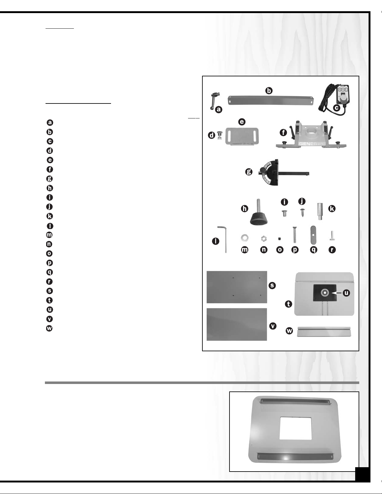
LIST OF
CONTENTS
QTY
RATCHET LEVER
. . . . . . . . . . . . . . . . . . . . . . . . . . .2
BRACKET
. . . . . . . . . . . . . . . . . . . . . . . . . . . . . . . .2
MAGNETIC SWITCH
. . . . . . . . . . . . . . . . . . . . . . . .1
T-BOLT WITH WASHER (FOR DUST SHIELD)
. . . . . .2
DUST SHIELD
. . . . . . . . . . . . . . . . . . . . . . . . . . . . . .1
FENCE ASSEMBLY
. . . . . . . . . . . . . . . . . . . . . . . . .1
MITER GAUGE
. . . . . . . . . . . . . . . . . . . . . . . . . . . .1
RUBBER LEVELING FOOT
. . . . . . . . . . . . . . . . . . . .4
CARRIAGE BOLTS
. . . . . . . . . . . . . . . . . . . . . . . . .20
WOOD SCREWS
. . . . . . . . . . . . . . . . . . . . . . . . . . .4
STARTING PIN
. . . . . . . . . . . . . . . . . . . . . . . . . . . . .1
ALEN KEY
. . . . . . . . . . . . . . . . . . . . . . . . . . . . . . . .1
WASHER
. . . . . . . . . . . . . . . . . . . . . . . . . . . . . . . .20
HEX HUT
. . . . . . . . . . . . . . . . . . . . . . . . . . . . . . . .20
LEVELING SETSCREWS
. . . . . . . . . . . . . . . . . . . . . .4
SCREW (3/16”)
. . . . . . . . . . . . . . . . . . . . . . . . . . .2
FIXING PLATE
. . . . . . . . . . . . . . . . . . . . . . . . . . . . .2
T-BOLT
. . . . . . . . . . . . . . . . . . . . . . . . . . . . . . . . . . .2
SIDE PANEL
. . . . . . . . . . . . . . . . . . . . . . . . . . . . . . .2
TABLE TOP
. . . . . . . . . . . . . . . . . . . . . . . . . . . . . . .1
TABLE INSERT PLATE
. . . . . . . . . . . . . . . . . . . . . . . .1
SHELF
. . . . . . . . . . . . . . . . . . . . . . . . . . . . . . . . . . .2
FENCE
. . . . . . . . . . . . . . . . . . . . . . . . . . . . . . . . . .2
UNP
ACKING
Carefully unpack and remove the unit and its components from the box and check for missing or damaged items
as per the list of contents below.
Note: Report any missing or damaged items to your General International distributor immediately.
ASSEMBLING THE ROUTER TABLE
Note: Secure all hex nuts hand-tight only until assembly has been
completed. Then place the stand on a flat surface to square it up
and tighten all the nuts.
1. Remove the table insert plate from the table top and set it
aside for now.
2. Place the table top upside down on a smooth flat surface.
3. Using the supplied wood screws attach the brackets to the
underside of the table (Fig. 1). Make sure you do not completely tighten the wood screws, the wood screws will be
tightened in a later step.
5
Fig. 1
Page 6

4. Using a bolt, washer, and nut attach the side panels to the
brackets as shown in Fig. 2 with the panels between the
brackets.
Note: The side panels have pre-drilled holes at one end, for the
leveling feet. Make sure when installing the side panels that these
holes remain visible, if you cannot see them the panel was
installed upside down.
5. With the side panels secured to the brackets, fully tighten the
wood screws mentioned in step 3.
6. Using 8 bolts, washers, and nuts per shelf,secure the shelves to
the side panels (Fig. 3). Place the top shelf into place first followed by the lower shelf.
7. Thread the leveling feet into the bottom of the side panels.
8. Turn the table over and place it on a flat level surface; tighten
all hex nuts and adjust the leveling feet if needed.
6
Fig. 3
MOUNTING A ROUTER
1. Make sure the router is “OFF” and disconnected from the
power source.
2. Flip the table insert plate upside down (concentric circle
ridges facing you) making sure to lay it on a flat surface.
3. Remove the slide plate from the base of your router (Fig. 4)
and then set the router on the insert plate.
4. Align the router base on the insert plate using the concentric
circle ridges on the Insert Plate (Fig. 5). Transfer the router
mounting hole locations onto the table insert plate using a
pencil.
5. Set the router aside; drill and countersink the holes you
marked in the previous step to the table insert plate.
6. Secure your router base to the insert plate using the screws
supplied with your router into the holes you just drilled in the
plate.
MAKE SURE THE HEADS OF THE SCREWS ARE SLIGHTLY
BELOW THE SURFACE OF THE PLATE. (FIG. 6.1)
7. Set the plate with the router attached into the opening on the
table and secure the plate to the table using the 2 screws and
fixing plates at diagonally opposite corners of the plate
(Fig. 6).
Fig. 6
Fig. 6.1
Fig. 2
Fig. 5
Concentric Circle
Ridges
Fig. 4
Page 7

TABLE INSERT
SETUP
Using the supplied allen key install a leveling setscrew into each
of the 4 corners on the table insert plate.
LEVELING THE TABLE INSERT PLATE
1. Using a straightedge check that the table insert plate is level
with the table.
2. Adjust the leveling setscrews in the 4 corners of the insert plate
as needed using the supplied allen key (Fig. 7).
TABLE INSERT RINGS
The table insert is supplied with 2 removable insert rings (1 red &
1 yellow) allowing the opening in the table to be changed to
suit the most common sizes of router bits (Fig. 8).
With both rings in place the opening is 1 1/4” (32 mm) in
diameter.
With the red inner ring removed, the opening is 2 5/8” (67 mm)
and with the yellow outer ring removed the opening is 3 7/8”
(98 mm).
ASSEMBLING AND INSTALLING THE FENCE
1. Stand the fence frame upright (Fig. 9); thread a T-bolt, thick
washer, and a locking lever into the predrilled holes on the
fence frame. Make sure that the washers are in-between the
fence frame and the locking levers. Do not fully tighten the Tbolts and/or locking levers.
2. Attach the fence frame to the table by sliding the t-bolts
(installed in the previous step) into the T-Slots on the table top
(Fig. 10).
Fig. 7
Fig. 8
Leveling Setscrew
1 1/4”
2 5/8”
3 7/8”
Mounting
Holes for
Starting Pin
USING THE LOCKING LEVERS
This router table uses spring-loaded levers.
These levers allow for easy tightening and
loosening without having to turn the lever a
full 360°.
To Tighten / Loosen the Levers
Turn the lever in the desired direction till it meets an obstruc-
tion. Lift and turn in the opposite direction while always keeping the lever held up. Release the handle, return to the first
step and repeat unit the lever is tightened or loosened.
Fig. 9
Fig. 10
Slide T-bolts into T-slots
on table top
7
Page 8

DUST SHIELD AND STARTING PIN
INSTALLING THE DUST SHIELD
1. Install the dust shield to the fence by sliding the T-bolts into the
T-slots.
2. Loosen knobs to slide the dust shield to the desired height –
retighten knobs to hold the shield in place (Fig. 12).
INST
ALLING THE STARTING PIN
Install the starting pin into one of the predrilled holes on the
table insert plate (Fig 13 or see page 7 - Fig. 8). For use as needed when freehand or template routing only.
INSTALLING AND USING THE MOVEABLE SWITCH BOX
Fig. 12
The supplied switch box features a magnetic back that allows
the switch to be placed anywhere on the metal surface of the
cabinet to best suit your needs or preferences.
With the switch on the box in the “off” position plug any 110V
router into the outlet on the switch box (Fig.14) turn the switch on
your router to the on position and then plug the cord from the
switch box into a standard 110V outlet. You can then turn the
router on or off using the switch box rather than having to reach
under the table to access the switch on the router.
The moveable switch box is equipped with a simple rocker style “on/off” switch featuring a removable lock out
safety key.
To prevent unauthorized use or unintentional start-up,
remove the safety key and store it in a safe place whenever the router table is not in use.
Fig. 14
POWER ON
POWER OFF
SAFETY KEY
(PREVENTS START-UP
WHEN REMOVED)
3. Loosely thread a T-bolt, washer and knob into the fence
frame. Allow the T-bolt to protrude approximately 1/4” to 1/2”
(Fig 11.1). Slide a fence face into the protruding T-bolt
making sure that the T-bolt slides into the aluminum T-slot
(Fig. 11.2), finish by tightening the knob. Repeat this step for
the second fence face.
Fig. 13
BEFORE TURNING ON THE SWITCH ON YOUR ROUTER,
MAKE SURE THE SWITCH ON THE SWITCH BOX IS IN THE
OFF POSITION AND THAT THE SWITCH BOX IS NOT YET
CONNECTED TO A POWER SOURCE.
8
Fig. 11.1 Fig. 11.2
1/4” to 1/2”
Page 9

WHEN JOINTING, GROOVE CUTTING, AND/OR PROFILE CUTTING BE SURE TO ATTACH THE SUPPLIED DUST SHIELD.
JOINTING AN EDGE
Jointing the edge of a board involves using a straight cutting
router bit to remove wood from the edge face of a board. The
result is a perfectly flat and square edge.
1. Install a straight cutting router bit into your router according to
the manufacturer’s instructions.
2. Snap the smallest table insert into the recessed hole that still
allows the router bit to rotate freely.
3. Loosen the locking lever and using the fence adjustment
knob adjust the outfeed fence lever so that it is flush with
the edge of the router bit.
4. Loosen the knobs and adjust the opening between the fences to allow the bit to clear the edge of both fences.
5. Raise or lower the bit slightly so that the bit is higher than the board’s thickness.
6. Adjust the infeed fence to the router bit center, so that the distance is equal to the desired depth of the cut.
Fig. 15
CONNECTING A DUST COLLECTOR
There is a 2 1/2” dust outlet on the rear of the fence assembly allowing for the connection of a dust collector (not
included).
Be sure to use an appropriate size hose and fittings (not included) and check that all connections are sealed tightly to minimize airborne dust.
If you do not already own a dust collection system, consider contacting your General® International distributor for
information on our complete line of dust collection systems or visit our website at: www.general.ca
BEFORE ROUTING CONNECT THE MACHINE TO A DUST COLLECTION SYSTEM.
ALWAYS TURN ON THE DUST COLLECTOR BEFORE STARTING THE ROUTER AND ALWAYS STOP THE ROUTER BEFORE
TURNING OFF THE DUST COLLECTOR.
OPERATING INSTRUCTIONS
MAKE SURE TO READ, UNDERSTAND, AND FOLLOW ALL OPERATING INSTRUCTIONS AND SAFETY GUIDELINES THAT
CAME WITH YOUR ROUTER – FAILURE TO DO SO MAY LEAD TO SERIOUS INJURY AND/OR DAMAGE TO THE ROUTER,
ROUTER TABLE, OR WORKPIECE.
BEFORE STARTING:
• Install the required bit in your router according to the instructions supplied with your router.
• Make sure that the router is firmly attached to the insert plate and that the plate is properly fitted and level in the
table opening.
• The router table should be installed on a flat, sturdy, and stable surface.
• When jointing, groove cutting, and/or profile cutting always perform a test cut on a scrap piece of wood before
cutting your final piece.
9
Page 10

PROFILE CUTTING
Profile cutting is usually performed using a bit with a guide bearing. The guide bearing controls the depth of cut into the edge
face of a board. A good example would be a chamfer bit
(Fig. 17).
The bearing rides along the uncut edge of the board while the
cutter removes the wood.
1. Mount a router bit into your router according to the manufacturer’s instructions.
2. Snap the smallest table insert into the recessed hole that still
allows the router bit to freely rotate.
3. Raise or lower the router bit to the desired height.
4. Loosen the knobs and adjust the opening between the
fences to allow the bit to clear the edge of both fences.
5. Adjust the fence back and away from the bit only enough to
allow the guide bearing to control the depth of cut.
6. Adjust the fence as close as possible to the bearing. The
fence will serve as a backup support, reducing the chance of
an accident.
Fig. 18
Fig. 17
GROOVE CUTTING
Beading is commonly defined as cutting a groove or bead in
the face of a board.
1. Mount a router bit into your router according to the manufacturer’s instructions.
2. Snap the smallest table insert into the recessed hole that still
allows the router bit to rotate freely.
3. Raise or lower the router bit to the desired height.
4. Loosen the knobs and adjust the opening between the
fences to allow the bit to clear the edge of both fences.
5. Adjust the main fence until the center of the bit has reached
the desired distance.
6. Align the infeed and outfeed fences parallel to each other using a machinist square or a straightedge (Fig. 16).
Fig. 16
Straightedge
The supplied miter gauge can be swiveled left or right to any
angle between 90° and 30° and has adjustable index stops at
90° and 45°.
To use a setting other than 90°,loosen the lock knob, , by turning it counter-clockwise, flip down the stop-lock tab, , and swivel the head of the gauge to the desired angle as shown on the
scale. Turn the lock knob clockwise to tighten it.
Fig. 19
USING THE MITER GAUGE
10
Page 11

If any of the miter gauge stops need adjusting turn the adjusting
screws (Fig. 20) in or out as needed while using a combination
square to check the 90 or 45 degree angles between the face of
the gauge and the guide bar. Once set, tighten down the lock
nuts to secure the adjusting screws in place.
ADDING AN AUXILIARY FENCE TO THE MITER GAUGE
To ensure safe accurate routing when using the miter gauge
with long narrow pieces the workpiece will require more support
than the narrow head of the gauge can provide and a homemade auxiliary hardwood fence should be attached to the face
of the gauge.
Make sure the wood for the fence is straight, not bowed, and of
an even thickness. Is should be at least 2” tall and extend far
enough from either side of the miter head to support more than
50% of the workpiece and come as close to the router bit as possible without touching. Drill 2 countersunk holes in the wood
(Fig. 21.1) corresponding to the mounting holes on the face of
the miter head (Fig. 21) tand use bolts and nuts (not supplied) to
secure the wood fence to the face of the miter head.
Fig. 20
Fig. 21
NOTES
Adjustment Screws
Countersunk holes
attached using bolts
and nuts to the face
of the miter head.
Fig. 21.1
11
Page 12

01
02
03
06
08
09
12
13
16
11
14
15
17
18
19
20
21
22
23
24
10
25
26
07
04
05
28
29
30
31
32
33
34
35
36
37
38
39
40
27
41
42
43
44
45
46
46
05
47
12
Page 13

PARTS LIST
40-040
REF. DIAG. PART N0. DESCRIPTION SPECIFICATION QTY
1 40040-01 POINTER 2
2 40040-02 SCALE 2
3 40040-03 FENCE 2
4 40040-04 WASHER 4
5 40040-05 KNOB 4
6 40040-06 SCREW 3/16” 2
7 40040-07 TABLE INSERT PLATE 1
8 40040-08 FIXING PLATE 2
9 40040-09 SET SCREW M6 4
10 40040-10 TABLE 1
11 40040-11 BRACKET 2
12 40040-12 SIDE PANELS 2
13 40040-13 NUT 20
14 40040-14 LOCK WASHER 20
15 40040-15 FLAT WASHER 20
16 40040-16 CARRIAGE BOLT 20
17 40040-17 LEVELING FOOT 4
18 40040-18 SHELF 2
19 40040-19 SCREW 4
20 40040-20 DUST SHIELD 1
21 40040-21 T-BOLT 4
22 40040-22 FENCE BRACKET 2
23 40040-23 RATCHET LEVER 2
24 40040-24 BOLT 2
25 40040-25 ADJUSTMENT KNOB 2
26 40040-26 SET SCREW 2
27 40040-27 DUST HOUSING 1
28 40040-28 T-SLOT 1
29 40040-29 MITER GAUGE ASSEMBLY 1
30 40040-30 HANDLE 1
31 40040-31 FLAT WASHER 1
32 40040-32 MITER GAUGE BODY 1
33 40040-33 SET SCREW 3/16” X 3/4” 3
34 40040-34 NUT 3/16” 3
35 40040-35 POINTER 1
36 40040-36 STOP TAB 1
37 40040-37 SET SCREW M5 X 8mm 1
38 40040-38 PIN 1
39 40040-39 GUIDE BAR 1
40 40040-40 PHILLIPS HEAD SCREW 1
41 40040-41 GUIDE WASHER 1
42 40040-42 STARTING PIN 1
43 40040-43 T-BOLT 2
44 40040-44 T-SLOT 2
45 40040-45 RATCHET LEVER 2
46 40040-46 FLAT WASHER 4
47 40040-47 SWITCH ASSEMBLY 1
13
Page 14

IMPORTANT: When ordering replacement parts, always give the model number, serial number of
the machine and part number. Also a brief description of each item and quantity
desired.
8360, Champ-d’Eau, Montreal (Quebec)
Canada H1P 1Y3
Tel.: (514) 326-1161
Fax : (514) 326-5565
Parts & Service
Fax : (514) 326-5555 Order Desk
orderdesk@general.ca
www.general.ca
40-040
 Loading...