

Page 1
SETUP & OPERATION MANUAL
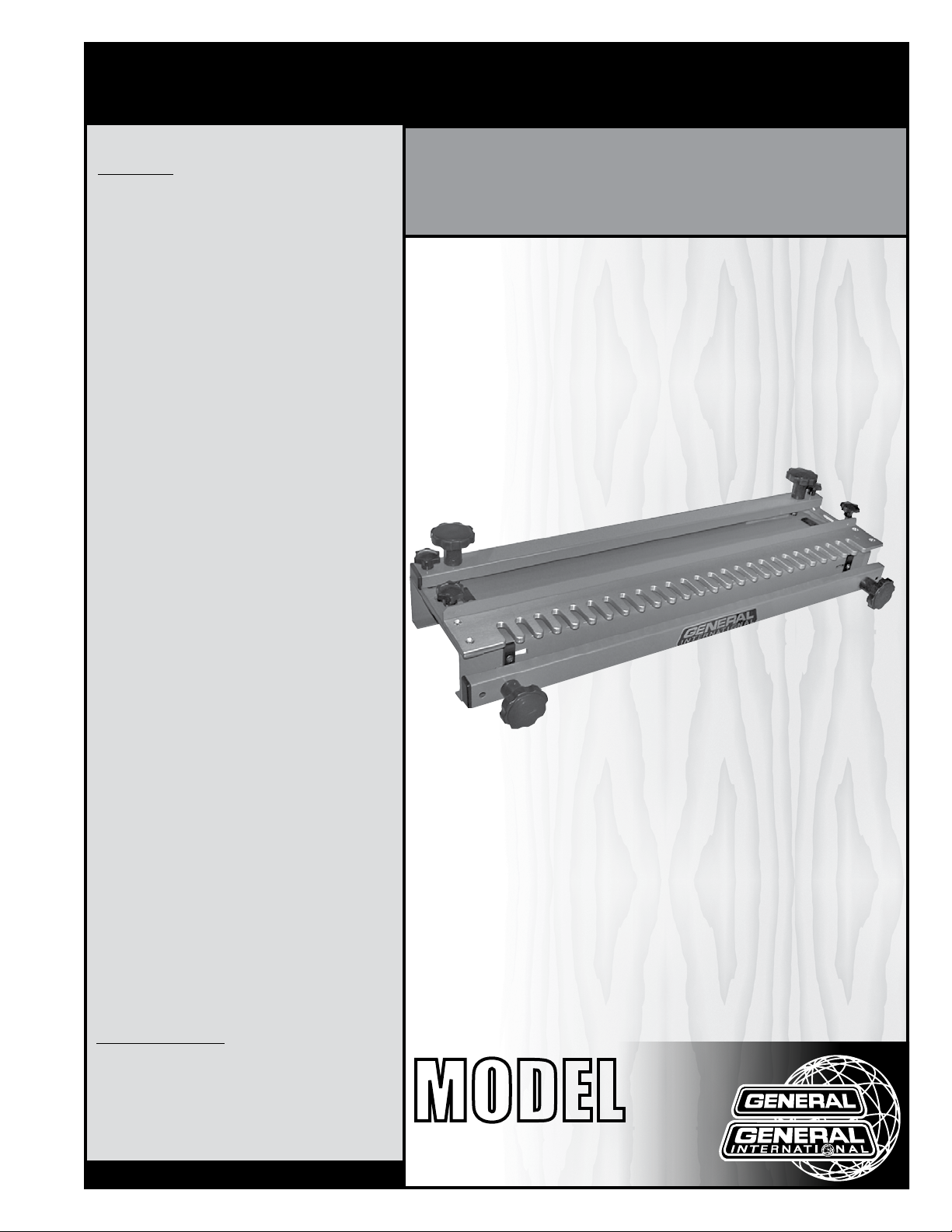
FEATURES
Male and female dovetail joints are cut simultaneously, to ensure perfectly matched dovetail
joints.
Side stops provided, allow repeated precise
dovetail joint cutting with one initial setting.
Comes with 1/2” half-blind template (#40-022).
24” DOVETAIL JIG
SPECIFICATIONS
• Thickness capacity
1/2” - 1 1/4” (13 mm - 32 mm)
• Dimensions
30 1/8” x 11 x 6 3/4” (765 x 280 x 170 mm)
• Weight
29 LBS (13 kg)
Version 2 / Revision 1 - June 2014
© Copyright General International 2014
MODEL
#
40-020
Page 2

GENERAL® INTERNATIONAL
8360 Champ-d’Eau, Montreal (Quebec) Canada H1P 1Y3
Telephone (514) 326-1161 • Fax (514) 326-5555 • www.general.ca
THANK YOU
for choosing this General® International item 40-020 (24”)
Dovetail jig. This dovetail jig has been carefully tested and inspected before shipment and if
properly used and maintained, will provide you with years of reliable service. For your safety,
as well as to ensure optimum performance and trouble-free operation, and to get the most
from your investment, please take the time to read this manual before assembling, installing
and operating the unit.
The manual’s purpose is to familiarize you with the safe operation, basic function, and features
of this dovetail jig as well as the set-up, maintenance and identification of its parts and
components. This manual is not intended as a substitute for formal woodworking instruction,
nor to offer the user instruction in the craft of woodworking. If you are not sure about the safety
of performing a certain operation or procedure, do not proceed until you can confirm, from
knowledgeable and qualified sources, that it is safe to do so.
Once you’ve read through these instructions, keep this manual handy for future reference.
DISCLAIMER: The information and specifications
in this manual pertain to the unit as it was supplied
from the factory at the time of printing. Because we
are committed to making constant improvements,
General® International reserves the right to make
changes to components, parts or features of this unit
as deemed necessary, without prior notice and without
obligation to install any such changes on previously
delivered units. Reasonable care is taken at the factory
to ensure that the specifications and information in
this manual corresponds with that of the unit with
which it was supplied. However, special orders and
“after factory” modifications may render some or all
information in this manual inapplicable to your unit.
Further, as several generations of this model of dovetail
jig and several versions of this manual may be in
circulation, if you own an earlier or later version of this
unit, this manual may not depict your unit exactly. If you
have any doubts or questions contact your retailer or
our support line with the model and serial number of
your unit for clarification.
Page 3

GENERAL® INTERNATIONAL WARRANTY
All component parts of General® International and Excalibur by General International® products
are carefully inspected during all stages of production and each unit is thoroughly inspected upon
completion of assembly.
Limited Lifetime Warranty
Because of our commitment to quality and customer satisfaction, General® International agrees to
repair or replace any part or component which upon examination, proves to be defective in either
workmanship or material to the original purchaser for the life of the tool. However, the Limited Lifetime
Warranty does not cover any product used for professional or commercial production purposes nor
for industrial or educational applications. Such cases are covered by our Standard 2-year Limited
Warranty only. The Limited Lifetime Warranty is also subject to the “Conditions and Exceptions” as listed
below.
Standard 2-Year Limited Warranty
All products not covered by our lifetime warranty including products used in commercial, industrial
and educational applications are warranted for a period of 2 years (24 months) from the date of
purchase. General® International agrees to repair or replace any part or component which upon
examination, proves to be defective in either workmanship or material to the original purchaser during
this 2-year warranty period, subject to the “conditions and exceptions” as listed below.
To file a Claim
To file a claim under our Standard 2-year Limited Warranty or under our Limited Lifetime Warranty,
all defective parts, components or machinery must be returned freight or postage prepaid to
General® International, or to a nearby distributor, repair center or other location designated by
General® International. For further details call our service department at 1-888-949-1161 or your local
distributor for assistance when filing your claim.
Along with the return of the product being claimed for warranty, a copy of the original proof of
purchase and a “letter of claim” must be included (a warranty claim form can also be used and can
be obtained, upon request, from General® International or an authorized distributor) clearly stating the
model and serial number of the unit (if applicable) and including an explanation of the complaint or
presumed defect in material or workmanship.
CONDITIONS AND EXCEPTIONS:
This coverage is extended to the original purchaser only. Prior warranty registration is not required but
documented proof of purchase i.e. a copy of original sales invoice or receipt showing the date and
location of the purchase as well as the purchase price paid, must be provided at the time of claim.
Warranty does not include failures, breakage or defects deemed after inspection by
General®International to have been directly or indirectly caused by or resulting from; improper use,
or lack of or improper maintenance, misuse or abuse, negligence, accidents, damage in handling
or transport, or normal wear and tear of any generally considered consumable parts or components.
Repairs made without the written consent of General® International will void all warranty.
Page 4

TABLE OF CONTENTS
Rules for safe operation .................................................................................................... 5
Identification of main parts and components .................................................................6
Unpacking ........................................................................................................................ 7
Assembly instructions .......................................................................................................7
Operating & set up......................................................................................................... 7-8
Fitting & adjusting ............................................................................................................. 8
Required tools based of template being used.................................................................9
Recommended optional accessories ..............................................................................9
Parts list & diagram ........................................................................................................10
Contact information ....................................................................................................... 12
Page 5

RULES FOR SAFE OPERATION
To help ensure safe operation, please take a moment to learn the machine’s applications and limitations,
as well as potential hazards. General
harmless for any injury that may result from the improper use of it’s equipment.
1. Learn the machine’s applications and limitations, as
well as the specific potential hazards particular to
this machine. Follow available safety instructions
and safety rules carefully.
2. Keep working area clean and be sure adequate
lighting is available.
3. Do not wear loose clothing, gloves, bracelets, neck-
laces, or ornaments. Wear face, eye, ear, respiratory
and body protection devices, as indicated for the
operation or environment.
4. Keep hands well away from router bits and all moving
parts. Do not clear chips and sawdust away wi
hands. Use a brush.
5. M
ake sure the router bit is moving at opera
speed before cutting.
6. Do not push the router bit to hard. The router bit will
perform better and be safer working at the rate for
which it was designed.
®
International disclaims any real or implied warranty and hold itself
13. Do not force the machine. It will do the job better
and be safer at a rate for which it was designed.
14. Keep guards in place and in working order. If a
guard must be removed for maintenance or clean ing make sure it is properly attached before using
the tool again.
15. Be sure that key and adjusting wrenches have been
removed before turning power on.
16. Use only accessories designed for the machine.
17. Make sure tool is properly grounded. If tool is equip-
th
ped with three-prong plug, it should be plugged into
a three-pole electrical receptacle. Never remove
the third prong.
tion
18. Always disconnect tool before servicing and when
changing accessories such as router bits.
19. Make sure that switch is in “OFF” position before
plugging in cord.
7. Whenever possible use a dust collector with shaving
hood to minimize health hazards.
8. Never leave the machine with the power on.
9. Keep children away. Make sure that visitors are kept
at a safe distance from the work area.
10. Use recommended speed router bit, accessory, and
workpiece material.
11. Never stand on tool. Serious injury could occur if the
tool is tipped or if the cutting tool is unintentionally
contacted.
12. Be sure the router bit is securely locked in the
machine.
20. Hold material firmly against the table.
21. Use ONLY recommended accessories. Use of acces sories NOT recommended by General International
may result in a risk of injury.
22. Do not use this dovetail jig for any purpose other
than its intended use. If used for other purposes,
General
plied warranty and holds itself harmless for any injury, which may result from that use.
®
International disclaims any real or im-
5
Page 6

IDENTIFICATION OF MAIN PARTS AND COMPONENTS
40-020
B
G
D
E
C
B
D
A
A. VERTICAL CLAMPING KNOB
B. HORIZONTAL CLAMPING KNOB
C. TEMPLATE LOCK KNOB
D. FENCE LOCK KNOB
A
F
E. TEMPLATE
F. VERTICAL STOP (2)
G. HORIZONTAL STOP (2)
6
Page 7

UNPACKING
Right
Carefully unpack and remove the unit and its components from its shipping container and check for missing or
damaged items.
NOTE: PLEASE REPORT ANY DAMAGED OR MISSING ITEMS TO YOUR GENERAL® INTERNATIONAL DISTRIBUTOR IMMEDIATELY.
LIST OF CONTENTS QTY
A.
24” DOVETAIL JIG .................................................................... 1
B. 1/2”ALUMINIUM TEMPLATE (INSTALLED ON JIG) ................... 1
A
OPERATION & SET-UP
You can mount the jig to a workbench through the two
mounting holes found at the rear of the jig. You can
also mount the jig to piece of plywood so that it can be
clamped to your workbench when needed.
TIP: ALWAYS SET-UP AND PRACTICE ON A TEST PIECE.
3
Left
4
(INSIDE)
Back
(INSIDE)
The 24” dovetail jig comes with a 1/2” aluminum template. It should be used with a 1/2” dovetail router bit
(1/4” shank, 14°), and a 1/2” guide bushing.
1. Lay out the workpieces and mark according to the
finished position as shown.
2. Slide the workpiece marked “Front” or “Back” B un-
der the horizontal clamping assembly as shown B.
The side marked inside should face up.
3. Set the horizontal stop E so that the edge of the workpiece lines up in the centre of one of the template
fingers as shown B.
4. Remove the template G by tightening the four screws
F.
5. Remove the vertical clamping assembly by unscrew-
ing the two knobs H.
6. Mark the workpiece 1/2” from the edge for template
finger width G. Adjust the vertical stop against the
square I.
7. Re-install the template and the vertical clamping assembly.
8. Slide the workpiece marked “Left” or “Right” under the
vertical clamping assembly. The side marked “inside”
should face out. Match up the numbers you marked.
9. Adjust the clamping pressure knobs so that the bar
is just over the workpiece. The workpiece should still
move freely, hold the workpiece in place by pushing
the lever. Excessive force should not be necessary to
clamp the workpiece.
10. Set the template back from the front edge of the
workpiece by approximately 1/8” as shown K.
Front
(OUTSIDE)
C
D
E
F
G
H
I
CENTRE
2
(OUTSIDE)
1
B
J
7
Page 8

11. Loosen the two knobs L to position the template.
Measure from the two ends of the workpiece to the
template to make sure the template is parallel to te
front edge of the workpiece.
12. The fence N should be set from the template finger
tip according to a simple equation found in “Calculating distance from fence to template finger”. Loosen the the two fence lock knobs M to position the
fence.
13. Set the router bit so it is approximately 11/16” lower
than the router base.
14. Rout off the front edge of the workpiece following
along the template fingers. Rout out the rest of the
material.
15. Remove the workpieces and verify for fit.
CALCULATING DISTANCE FROM FENCE TO TEMPLATE FINGER
EQUATION
STOCK THICKNESS TIMES TWO, PLUS ROUTER BASE RADIUS*, MINUS BIT RADIUS,
EQUALS DISTANCE FROM TEMPLATE FINGER TO FENCE.
L
M
N
K
Example
Stock thickness is 1/2”
1/2” x 2 = 1”
*Radius = Diameter ÷ 2
Router base radius is 3”
1” + 3”= 4
Router base bit
radius is 1/4”
4−1/4” = 3 3/4”
Then distance from
fence to template
finger is 3 3/4”
FITTING & ADJUSTING
• If the dovetail fit is too tight; decrease the router bit distance from router base slightly.
• If the dovetail fit is too loose increase the router bit distance from the router base slightly.
• If the pins on the side piece fit too deeply in the tails of the front or the back piece; then the cut is too deep. Move
• the fence forward the same amount the pins are exposed.
• If the side piece sticks out from the front or the back piece; then the cut is too shallow. Move the fence back the
same amount the sides stick out.
• If the edges on the front and side piece do not match adjust the stop. The front stop must be offset from the top
stop the width of the template finger at 1/2”.
• When you have the jig properly adjusted, you can dovetail the actual drawer parts.
NOTES
• Joints for the left front corner and the right rear corner of a drawer or a box are cut on the left side of the jig. Joints
for the right front corner and the left rear corner of a drawer or a box are cut on the right side of the jig.
• The drawer sides should be cut to the finished height. They can be left longer and cut to the finished length later.
• Once the desired router bit height is established make a simple gauge block out of a hardwood to quickly get the cor rect setting in the future.
• Once the stops are set properly and you have obtained the desired results use a scribe to mark the stop locations.
8
Page 9

REQUIRED TOOLS BASED ON TEMPLATE BEING USED
Dovetail template
1/4” (6 mm) 1/4” (6 mm) x 8° 5/16” (8 mm) 5 mm
1/2” (13 mm) 1/2” (13 mm) x 14° 3/8” (9.5 mm) 12.4 mm
1/2” (13 mm) 1/2” (13 mm) x 14° 7/16 (11 mm) 6.4 mm
1/2” (13 mm) 5/8” (14 mm) x 14° 15/16” (12 mm) 9.6 mm
1/2” (13 mm) 5/8” (14 mm) x 14° 1/2” (13 mm) 12.4 mm
Box joints
1/4” (6.35 mm) 1/4” 5/16” (8 mm)
3/8” (9.5 mm) 3/8” 1/2” (13 mm)
1/2” (13 mm) 1/2” 5/8” (14 mm)
Router bit (1/4” shank) Guide bushing Depth of cut
Straight Bit (1/4” shank)
Guide bushing Depth of cut
RECOMMENDED OPTIONAL ACCESSORIES
Here is a sampling of optional accessories available from your local General International dealer.
For more information about our products, please visit our website at www.general.ca
Exact thick-
ness of the
workpiece
Item #40-026 - 1/4”, #40-027 - 3/8”, #40-028 - 1/2” (Box joint template).
Item #40-021 - 1/4”, #40-022 - 1/2” (Half-blind template).
ALUMINUM DOVETAIL TEMPLATES
9
Page 10

DIAGRAM & PARTS LIST
4
14
15
10
6
12
3
16
8
5
5
1
"
2
9
11
7
2
9
4
1
3
13
10
IMPORTANT: When ordering replacement parts, always give the model number, serial number of the
machine and part number. Also a brief description of each item and quantity desired.
NO. PIECE DESCRIPTION SPECIFICATION QTY
40020-01 BASE 1
40020-02 THREADED BUSHING 4
40020-03 CLAMP BRACKET 2
40020-04 CLAMP KNOB 4
40020-05 KNOB 4
40020-06 FENCE 1
40020-07 BRACKET 2
40020-08 1/2” HALF BLIND DOVETAIL TEMPLATE (#40-022) 1
40020-09 STOPS (LONG) 2
40020-10 STOPS (SHORTS) 2
40020-11 FLAT WASHER 2
40020-12 SPRING 4
40020-13 THREADED BRACKET 4
40020-14 END CAP 4
40020-15 FLAT PHILLIPS MACHINE SCREW 10-24 X 5/8” 8
40020-16 FLAT PHILLIPS MACHINE SCREW 1/4”-20 X 3/8” 4
10
Page 11

NOTES
11
Page 12

8360 Champ-d’Eau, Montreal (Quebec) Canada H1P 1Y3
Tel.: (514) 326-1161
Fax: (514) 326-5565 - Parts & Service / (514) 326-5555 - Order Desk
orderdesk@general.ca
www.general.ca
Follow us:
12
 Loading...