

Page 1

SPECIFICATIONS
SPINDLE SPEEDS (3)
1350, 2250 & 3500 RPM
SWING O
VER BED
4” (102 MM)
SWING O
VER TOOL REST
2 1/2” (64 MM)
DIST
ANCE BETWEEN CENTERS
12” (102 mm)
SPINDLE
THREAD
3/4” (19 MM) – 16 TPI
T
AILSTOCK THROUGH HOLE
3/8” (10 MM)
MORSE
TAPER
MT#1 (HEADSTOCK AND TAILSTOCK)
SELF-EJECTING
TRAVEL
1” (25 MM)
T
OOL REST
6” (152 MM
F
ACE PLATE
2.5” (64 MM)
MO
TOR
1/5 HP, 110V, 1.2 A, 3450 RPM
WEIGHT
15.5 LBS (7 KG)
SETUP & OPERATION MANUAL
MODEL
#25-010 M1
PEN TURNING MINI-LATHE
FEATURES
Designed and built specifically for turning
pens and other smaller hobby type projects.
Quick lock control levers easily position tool
rest.
Extruded aluminum frame, head and tailstock.
Maximum distance of 12” between centers.
Quiet, smooth running 1/5 HP motor.
3 speeds: 1350, 2250 & 3500 RPM.
Included accessories:
• Live center
• Spur center
• Knockout bar
• See-through lathe guard
• Bonus! Pen turning mandrel set
REVISION 1 - November 23/10
© Copyright General® International 11/2010
Page 2

THANK YOU
for choosing this General®International model 25-010 Pen Turning
Lathe. This lathe has been carefully tested and inspected before shipment and if properly used
and maintained, will provide you with years of reliable service. For your safety, as well as to
ensure optimum performance and trouble-free operation, and to get the most from your
investment, please take the time to read this manual before assembling, installing and operating the unit.
The manual’s purpose is to familiarize you with the safe operation, basic function, and features
of this wood lathe as well as the set-up, maintenance and identification of its parts and components. This manual is not intended as a substitute for formal woodworking instruction, nor to
offer the user instruction in the craft of woodworking. If you are not sure about the safety of
performing a certain operation or procedure, do not proceed until you can confirm, from
knowledgeable and qualified sources, that it is safe to do so.
Once you’ve read through these instructions, keep this manual handy for future reference.
Disclaimer:
The information and specifications in this
manual pertain to the unit as it was supplied from the
factory at the time of printing. Because we are committed to making constant improvements, General
®
International reserves the right to make changes to
components, parts or features of this unit as deemed
necessary,without prior notice and without obligation to
install any such changes on previously delivered units.
Reasonable care is taken at the factory to ensure that
the specifications and information in this manual corresponds with that of the unit with which it was supplied.
However, special orders and “after factory” modifications may render some or all information in this manual
inapplicable to your machine. Further, as several generations of this model of wood lathe and several versions
of this manual may be in circulation, if you own an earlier or later version of this unit, this manual may not
depict your machine exactly. If you have any doubts or
questions contact your retailer or our support line with
the model and serial number of your unit for clarification.
GENERAL® INTERNATIONAL
8360 Champ-d’Eau, Montreal (Quebec) Canada H1P 1Y3
Telephone (514) 326-1161 • Fax (514) 326-5555 • www.general.ca
Page 3

All component parts of General®, General® International and Excalibur by General
International ® products are carefully inspected during all stages of production and each unit
is thoroughly inspected upon completion of assembly.
Limited Lifetime
Warranty
Because of our commitment to quality and customer satisfaction, General® and General®
International agree to repair or replace any part or component which upon examination,
proves to be defective in either workmanship or material to the original purchaser for the life
of the tool.
However, the Limited Lifetime Warranty does not cover any product used for professionnal or commercial production purposes nor for industrial or educational applications.
Such cases are covered by our Standard 2-year Limited Warranty only. The Limited Lifetime
Warranty is also subject to the “Conditions and Exceptions” as listed below.
Standard 2-Year Limited Warranty
All products not covered by our lifetime warranty including products used in commercial,
industrial and educational applications are warranted for a period of 2 years (24 months) from
the date of purchase. General® and General® International agree to repair or replace any
part or component which upon examination, proves to be defective in either workmanship or
material to the original purchaser during this 2-year warranty period, subject to the “conditions
and exceptions” as listed below.
T
o file a Claim
To file a claim under our Standard 2-year Limited Warranty or under our Limited Lifetime
Warranty, all defective parts, components or machinery must be returned freight or postage
prepaid to General® International, or to a nearby distributor, repair center or other location
designated by General® International. For further details call our service department at 1-888949-1161 or your local distributor for assistance when filing your claim.
Along with the return of the product being claimed for warranty, a copy of the original proof
of purchase and a “letter of claim”must be included (a warranty claim form can also be used
and can be obtained, upon request, from General® International or an authorized distributor)
clearly stating the model and serial number of the unit (if applicable) and including an explanation of the complaint or presumed defect in material or workmanship.
GENERAL®& GENERAL®INTERNATIONAL WARRANTY
CONDITIONS AND EXCEPTIONS:
This coverage is extended to the original purchaser only. Prior warranty registration is not
required but documented proof of purchase i.e. a copy of original sales invoice or receipt
showing the date and location of the purchase as well as the purchase price paid, must be
provided at the time of claim.
Warranty does not include failures, breakage or defects deemed after inspection by General®
or General® International to have been directly or indirectly caused by or resulting from;
improper use, or lack of or improper maintenance, misuse or abuse, negligence, accidents,
damage in handling or transport, or normal wear and tear of any generally considered consumable parts or components.
Repairs made without the written consent of General® Internationallwill void all warranty.
Page 4

TABLE OF CONTENTS
Rules for safe operation . . . . . . . . . . . . . . .5
Electrical requirements . . . . . . . . . . . . . . .6
Grounding instructions . . . . . . . . . . . . . . . . . . . . . . .6
Circuit capacity . . . . . . . . . . . . . . . . . . . . . . . . . . . . .6
Extension cord . . . . . . . . . . . . . . . . . . . . . . . . . . . . . .6
Identification of main parts
and components . . . . . . . . . . . . . . . . . . . .
7
Basic functions . . . . . . . . . . . . . . . . . . . . .8
Unpacking . . . . . . . . . . . . . . . . . . . . . . . . .8
List of contents . . . . . . . . . . . . . . . . . . . . . . . . . . . . . .8
Installation & Assembly . . . . . . . . . . . . .9-10
Install the lathe guard . . . . . . . . . . . . . . . . . . . . . . .10
Basic adjustments & controls . . . . . . . .10-13
Connecting to a power source . . . . . . . . . . . . . . .10
On/Off power switch . . . . . . . . . . . . . . . . . . . . . . . .10
Changing spindle speed . . . . . . . . . . . . . . . . . . . .11
Tool rest carriage & tool rest adjustments . . . . . .11
Mounting & removing the headstock spur
center and face plate . . . . . . . . . . . . . . . . . . . . . .12
Mounting & removing the tailstock live center . .12
Moving tailstock quill in / out . . . . . . . . . . . . . . . .13
Tailstock movement . . . . . . . . . . . . . . . . . . . . . . . . .13
Mounting a pen blank on the pen turning
mandrel set . . . . . . . . . . . . . . . . . . . . . . . . . . . . . . .13
Mounting a workpiece to the face plate . . . . . . .14
Periodic Maintenance . . . . . . . . . . . . . . . .14
Recommended optional accessories . . . . .15
Parts list & diagrams . . . . . . . . . . . . . .16-17
Page 5

RULES FOR SAFE OPERATION
To help ensure safe operation, please take a moment to learn the machine’s applications and limitations, as well as potential hazards. General® International disclaims any real or implied warranty and holds itself harmless for any injury that
may result from improper use of its equipment.
1. Do not operate the wood turning lathe when tired,
distracted, or under the effects of drugs, alcohol or
any medication that impairs reflexes or alertness.
2. The working area should be well lit, clean and free
of debris.
3. Keep children and visitors at a safe distance when
the wood turning lathe is in operation; do not per
mit them to operate the wood turning lathe.
4. Childproof and tamper proof your shop and all
machinery with locks, master electrical switches
and switch keys, to prevent unauthorized or unsupervised use.
5. Stay alert! Give your work your undivided atten-
tion. Even a momentary distraction can lead to serious injury.
6. Fine particulate dust is a carcinogen that can be
hazardous to health. Work in a well-ventilated area
and whenever possible use a dust collector and
wear eye, ear and respiratory protection devices.
7. Do not wear loose clothing, gloves, bracelets,neck-
laces or other jewelry while the wood turning lathe
is in operation. Wear protective hair covering to
contain long hair and wear non-slip footwear.
8. Be sure that adjusting wrenches, tools, drinks and
other clutter are removed from the machine before
operating.
9. Keep hands well away from the spindle, the spin
ning workpiece, and all moving parts. Use a brush,
not hands, to clear away chips and dust.
10. Do not use stock containing defects such as che-
cks, splits, cracks, knots or foreign objects. Before
starting, inspect stock and remove all foreign objects such as dirt, nails, staples or any object that
could damage a tool or become dislodged and
fly free and cause injury.
11. Select appropriate turning speed for the size and
type of workpiece being turned and use lowest
speed when starting a new workpiece.
12. Before turning on the wood turning lathe, make
sure the workpiece is securely installed between
centers and that all locking levers and moveable
or removable parts are tightened down and secured.
13. Adjust the tool rest parallel and as close as possible
to the workpiece and before starting the wood turning lathe turn the workpiece by hand, at least one
full rotation to make sure that it does not come in
contact with the tool rest.
14. Maintain turning tools with care. Keep turning tools
sharp and clean for best and safest performance.
15. Avoid working from awkward or off balance posi
tions. Do not overreach and keep both feet on floor.
16. Keep guards in place and in working order. If a
guard must be removed for maintenance or cleaning be sure it is properly re-attached before using
the tool again.
17. Use of parts and accessories NOT recommended
by
GENERAL® INTERNATIONAL
may result in equip-
ment malfunction or risk of injury.
18. Never stand on machinery. Serious injury could
result if the tool is tipped over.
19. Always disconnect the tool from the power source
before servicing, changing accessories, performing any maintenance or cleaning, or if the
machine will be left unattended.
20. Make sure that switch is in
the “OFF”
position before
plugging in the power cord.
21. Make sure the tool is properly grounded. If equip-
ped with a 3-prong plug it should be used with a
three-pole receptacle. Never remove the third
prong.
22. Do not use this wood turning lathe for other than its
intended use. If used for other purposes,
GENERAL®
INTERNATIONAL
disclaims any real implied warranty
and holds itself harmless for any injury, which may
result from that use.
5
Page 6
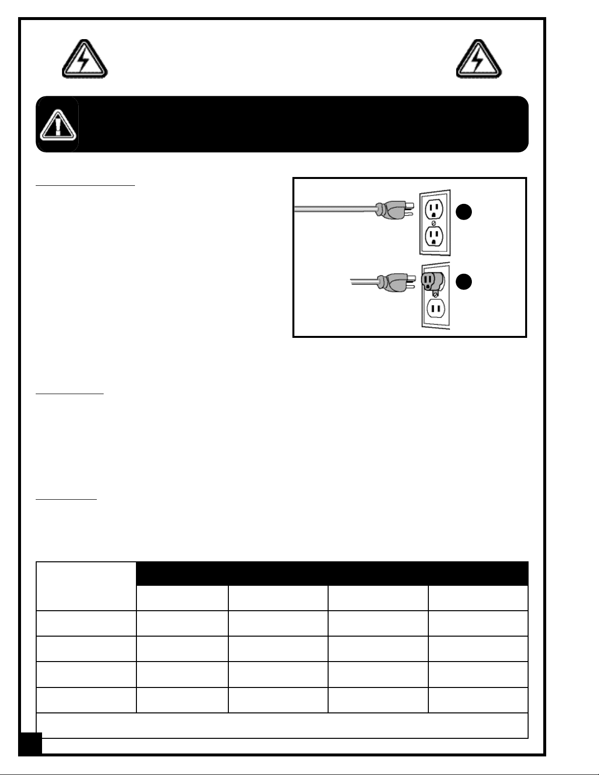
GROUNDING INSTRUCTIONS
In the event of an electrical malfunction or short circuit,
grounding reduces the risk of electric shock. The motor
of this machine is wired for 110V single phase operation and is equipped with a 3-conductor cord and a 3prong grounding plug to fit a grounded type receptacle A. Do not remove the 3rd prong (grounding pin) to
make it fit into an old 2-hole wall socket or extension
cord. If an adaptor plug is used B, it must be attached
to the metal screw of the receptacle.
Note: The use of an adaptor plug is illegal in some
areas. Check your local codes. If you have any doubts
or if the supplied plug does not correspond to your
electrical outlet, consult a qualified eletrician before
proceeding.
EXTENSION CORD
If you find it necessary to use an extension cord with your machine make sure the cord rating is suitable for the
amperage listed on the motor I.D. plate. An undersized cord will cause a drop in line voltage resulting in loss of
power and overheating. The accompanying chart shows the correct size extension cord to be used based on cord
length and motor I.D. plate amp rating. If in doubt, use the next heavier gauge. The smaller the number, the heavier
the gauge.
AMPERES
(AMPS)
EXTENSION CORD LENGTH
25 feet 50 feet 100 feet 150 feet
<5 18 16 16 14
6 TO 10 18 16 14 12
10 TO 12 16 16 14 12
12 TO 16 14 12 *NR *NR
*NR=Not Recommended
BEFORE CONNECTING THE MACHINE TO THE POWER SOURCE, VERIFY THAT THE VOLTAGE OF YOUR POWER SUPPLY CORRESPONDS
WITH THE VOLTAGE SPECIFIED ON THE MOTOR I.D. NAMEPLATE. A POWER SOURCE WITH GREATER VOLTAGE THAN NEEDED CAN
RESULT IN SERIOUS INJURY TO THE USER AS WELL AS DAMAGE TO THE MACHINE.IF IN DOUBT,CONTACT A QUALIFIED ELECTRICIAN
BEFORE CONNECTING TO THE POWER SOURCE.
THIS TOOL IS FOR INDOOR USE ONLY. DO NOT EXPOSE TO RAIN OR USE IN WET OR DAMP LOCATIONS.
ELECTRICAL REQUIREMENTS
A
B
CIRCUIT CAPACITY
Make sure that the wires in your circuit are capable of handling the amperage draw from your machine, as well as
any other machines that could be operating on the same circuit. If you are unsure, consult a qualified electrician.
If the circuit breaker trips or the fuse blows regularly, your machine may be operating on a circuit that is close to its
amperage draw capacity. However, if an unusual amperage draw does not exist and a power failure still occurs,
contact a qualified technician or our service department.
6
Page 7

PEN TURNING MINI-LATHE
25-010 M1
IDENTIFICATION OF MAIN PARTS AND COMPONENTS
A- PULLEY COVER
B- HEADSTOCK
C- FACE PLATE
D- SPUR CENTER
E- LATHE GUARD
F- TOOL REST LOCKING LEVER
G- TOOL REST CARRIAGE LEVER
H- TOOL REST
I- LIVE CENTER
J- TAILSTOCK QUILL LOCKING LEVER
K- TAILSTOCK
L- ON/OFF SWITCH
M- LATHE BED
N- MOUNTING FEET
O- SPINDLE PULLEY
P- DRIVE BELT
Q- DRIVE PULLEY
R- ADJUSTMENT NUT
S- TAILSTOCK LOCKING LEVER
7
O
P
Q
S
R
A
C
E
F
H
I
J
K
B
D
N
M
G
L
N
Page 8

UNPACKING
BASIC FUNCTIONS
This General International model 25-010 M1 Pen Turning Mini-Lathe is designed specifically for small hobby type
wood turning projects. With a maximum swing over bed of 4”, a distance between centers of 12”, and 3 speeds
(1350, 2250 & 3500 RPM),the 25-010 M1 is ideal for small turnings such as pens, as well as bowls and small spindles.
A simple belt re-positioning on the drive pulleys, allows the operator to select the desired speed.
This lathe can be mounted to your own homemade stand or secured to your workbench. The 25-010 M1 comes
equipped with a selection of the most commonly used accessories, including a 2.5” face plate for bowl turning, a
pen turning mandrel set for pen turning, and both live and spur center for typical spindle turning, to allow the user
to begin turning (turning tools not supplied) after a few minutes of assembly and set-up, right out of the box.
The 25-010 M1 Pen Turning Mini-Lathe is designed to be compatible with all aftermarket turning accessories using
MT#1 Morse taper in both the headstock, and tailstock and the headstock spindle threads are compatible with all
3/4” dia x 16 TPI female threaded chucks and face plates.
B
C
H
F
G
E
D
I
Carefully unpack and remove the lathe and its components from the box and check for damaged or missing
items as per the list of contents below.
NOTE: Please report any damaged or missing items to your
General International distributor immediately.
LIST OF CONTENTS QTY
A - WOOD LATHE (NOT SHOWN)..............................................1
B - LATHE GUARD.......................................................................1
C - GUARD SUPPORT ARM.........................................................1
D - KNOCK-OUT BAR..................................................................1
E - MOUNTING FEET...................................................................2
F - FLAT WASHER .......................................................................4
G - CAP SCREW..........................................................................4
H - SQUARE NUT .........................................................................4
I - 3 MM ALLEN KEY..................................................................1
J - 5 MM ALLEN KEY..................................................................1
K - SPUR CENTER* ......................................................................1
L - LIVE CENTER* .......................................................................1
M - FACE PLATE* .........................................................................1
*Already installed on the lathe
PEN TURNING MANDREL SET
N - ADAPTER SLEEVE...................................................................1
O - BUSHING...............................................................................1
P - THUMB NUT ...........................................................................1
Q - MANDREL SHAFT...................................................................1
PEN TURNING MANDREL SET
*
K
*
M
*
L
J
8
N
O
P
Q
Page 9

INSTALLATION & ASSEMBLY
For your convenience this lathe is shipped from the factory partially assembled and requires only minimal assembly and set-up before being put into service.
SERIOUS PERSONAL INJURY COULD OCCUR IF YOU CONNECT THE MACHINE TO THE POWER SOURCE
BEFORE YOU HAVE COMPLETED THE INSTALLATION AND ASSEMBLY STEPS. DO NOT CONNECT THE MACHINE
TO THE POWER SOURCE UNTIL INSTRUCTED TO DO SO.
1. Loosely attach two cap screws, flat washers and
square nuts in the assembly order shown to both
mounting foot.
3. Using the supplied 5 mm allen key, tighten the two
square nut/cap screw assemblies to secure the feet
to the lathe.
The unit should be installed on a flat, sturdy and stable
surface able to support the weight of the machine and
the workpiece with ease.
Never install the lathe over the edge of a table or workbench.
2. Attach the mounting feet to the lathe by sliding the
square nuts into the t-slots under the lathe.
If a permanent shop placement is practical, consider
drilling matching through holes in the mounting surface of your workbench or stand’s platform to bolt the
lathe in place using the fasteners shown in A (not
included), in the assembly order shown in B.
HEX HEAD BOLT
FLAT WASHERS
LOCK WASHER
HEX NUT
A
B
9
Page 10

10
INST
ALL THE LATHE GUARD
1. Attach the lathe guard support arm to the rear of the tool rest carriage as shown in A and tighten using the sup-
plied 3 mm allen key.
2. Attach the lathe guard to its support arm using the bolt and wing nut already mounted to the lathe guard support bracket, B.
A
CONNECTING TO A POWER SOURCE
TO REDUCE THE RISK OF SHOCK OR FIRE DO NOT
OPERATE THE UNIT WITH A DAMAGED POWER CORD
OR PLUG. REPLACE DAMAGED CORD OR PLUG IMMEDIATELY.
TO AVOID UNEXPECTED OR UNINTENTIONAL START-UP,
MAKE SURE THAT THE POWER SWITCH IS IN THE OFF
POSITION BEFORE CONNECTING TO A POWER
SOURCE.
Once the assembly steps have been completed and the
unit is safely secured to a work surface, uncoil the power
cord and plug the power cord into an appropriate outlet.
Refer back to section “Electrical Requirements” and make
sure all requirements and grounding instructions are followed.
BASIC ADJUSTMENTS & CONTROLS
SWITCH OFF
ON/OFF POWER SWITCH
SAFETY KEY
(PREVENTS START-UP
WHEN REMOVED)
POWER ON POWER OFF
A
B C
This lathe is equipped with a rocker style ON/OFF
switch located on the front right hand side of the lathe.
TO PREVENT UNWANTED OR UNAUTHORIZED
START-UP OR USAGE, REMOVE THE LOCK-OUT
KEY AND STORE IT IN A SAFE PLACE, OUT OF THE
REACH OF CHILDREN, WHENEVER THE LATHE IS
NOT IN USE.
- To start the lathe, insert the lock-out key A and pull
up on the lower portion of the switch as shown in B.
- To stop the lathe, push down on the switch, C.
B
Page 11

CHANGING SPINDLE SPEED
By changing the positioning of the drive belt from one set of pulleys to the other, the user can select between 3 spindle speeds - 1350, 2250 & 3500 Revolutions Per Minute (RPM) - depending on the wood turning application.
Note
Turning speeds vary depending on the size and diameter of the workpiece as well as which stage you are at in the over-
all turning process.
When turning a smaller diameter workpiece, a higher spindle speed is recommended. Proper spindle speed selection comes
with practice and experience and when in doubt always start at a slower speed increasing when you are sure that it is
safe to do so.
1. Turn off and unplug the machine from the power source before opening the belt guard or before perform-
ing any maintenance or adjustments.
2. To access the belt and pulleys, loosen the pulley cover lock screw using the supplied 5 mm allen key as
shown in A.
3. Open the pulley case cover and set the belt by hand to the required pulley position (High/Medium/Low), B.
A B
High: 3500 RPM
Medium: 2250 RPM
Low: 1350 RPM
Changing between the 3 speeds
requires moving the drive belt from
one set of drive pulleys to another
(H, M or L).
3 SPEEDS
TURN OFF AND UNPLUG THE MACHINE FROM THE POWER SOURCE BEFORE OPENING THE BELT GUARD OR BEFORE
PERFORMING ANY MAINTENANCE OR ADJUSTMENTS.
TOOL REST CARRIAGE & TOOL REST ADJUSTMENTS
A
B
The tool rest carriage can be moved along the bed
slide ways as needed.
Loosen the tool rest carriage lever A and move the carriage to the desired location. Re-tighten the lever
securely after adjustment.
The tool rest should be adjusted so that its top is 1/8"
above the center of the workpiece.
Loosen the tool rest locking lever B and adjust the
height and position of the tool rest as needed. Re-tighten the lever securely after adjustment.
11
Page 12

12
MOUNTING & REMOVING THE HEADSTOCK SPUR CENTER AND FACE PLATE
I
H
To remo
ve the headstock spur center:
Knock it out from the opposite end of the spindle,using
the supplied knock-out-bar D, as shown in E.
Note: When knocking out the spur center, always hold it by
hand to prevent it from falling.
E
A
B
C
D
G
To remove the face plate:
Unlock the face plate by inserting the supplied knock
out bar in the spindle hole, F, to keep the spindle from
turning while unscrewing the face plate, G.
F
T
o install the headstock spur center:
Make sure the shank of the spur center H and the
spindle hole are clean and free of debris, and
then fit the spur center firmly in the spindle hole by
hand I.
The headstock spindle has an MT#1 taper hole A into
which the spur center fits. The spur center can be installed either with the face plate on, B, or removed, C.
The tailstock has an MT#1 taper hole into which the live
center fits.
1. Make sure the shank of the live center and the tail-
stock hole are clean and free of debris and fit the
live center firmly in the spindle hole by hand J.
MOUNTING & REMOVING THE TAILSTOCK LIVE CENTER
J
TAILSTOCK REAR VIEW
M
L
K
To remove the live center from the tailstock quill:
Loosen the tailstock quill locking lever L and move the
quill out by turning the quill movement adjustment nut
K until the quill end is nearly inside the tailstock and
the live center can be removed by hand.
Note: When removing the live center, always hold it by
hand to prevent it from falling M.
Page 13

The tailstock quill can be moved in and out of the tailstock casting A by turning the tailstock quill adjustment nut B.
1. To move the tailstock quill, loosen the quill locking
lever I.
2. Turn the adjustment nut J to move the quill as
needed.
3. Re-tighten the quill locking lever to secure the quill
in position.
MOVING TAILSTOCK QUILL IN / OUT
The tailstock is used to support the other end of the
workpiece to be turned and can be moved along the
bed slideways to suit the length of the workpiece, D.To
move the tailstock on the bed:
1. Loosen the tailstock locking lever E.
2. Move the tailstock by hand to the desired location
on the bed.
3. Retighten the tailstock locking lever to secure the
tailstock in position.
TAILSTOCK MOVEMENT
D
E
REAR VIEW
C
MOUNTING A PEN BL
ANK ON THE PEN TURNING MANDREL SET
This Pen turning mini-lathe is supplied with a convenient pen turning mandrel set allowing for pre-drilled pen blank
turning.
1. Thread the adapter sleeve on the mandrel shaft as shown in A.
2. Insert the mandrel shaft through the hole in your pen blank as shown in B.
3. Insert the number of bushings required to fill the space remaining on the shaft up to its threaded end, C, then
thread the thumb nut on the shaft as shown to secure the pen blank and bushings in place, D.
4. Fit the adapter sleeve firmly in the spindle hole by hand E.
5. Move the tailstock along the bed slideways and/or adjust the tailstock quill so that the other end of the pen
mandrel shaft is supported by the live center as shown in F.
A
B
E
13
B
F
C
D
Page 14

PERIODIC MAINTENANCE
•
Keep the unit clean and free of dust by wiping with a cloth or vacuuming off any woodchips or dust after each
use.
•
All bearings are sealed and permanently lubricated and no further lubrication is required.
•
Regular applications of a surface protectant/lubricant will help prevent rust and keep the tool rest, head, and
tailstock sliding smooth on the bedway.
•
Periodically inspect the power cord and plug for damage. Replace the power cord and the plug at the first
signs of visible damage.
14
Notes
MOUNTING A WORKPIECE TO THE FACE PLATE
For turning applications where the workpiece cannot be secured between the headstock and tailstock centers
(such as bowl turning) the face plate must be used to secure the workpiece to the headstock spindle.
1. With the face plate removed from the lathe (if needed, refer back to section “Mounting & removing the head-
stock spur center” on page 12), mount the workpiece onto the face plate with wood screws (not included) through the mounting holes from the back of the face plate.Make sure the screws are not so long that they
will enter the area of the workpiece where the material is to be removed.
2. Thread the face plate back on the lathe.
Page 15

RECOMMENDED OPTIONAL ACCESSORIES
5 Piece Woodturning Mini- Chisel Set - #25-250
Made from high quality high-speed steel with solid
hardwood handles.
Designed specially for smaller turning such as pen
making and other small hobby type projects.
Includes a 3/4” diamond parting tool, a 1/2” round
nose scraper, a 1” skew chisel, and a 1/2”bowl gouge.
Portable Dust Collector - #10-050M1
Designed for flexibility and mobility. Featuring an adjustable multi-position support arm and a wide, rotating
dust hood this unit is ideal for use on wood lathes.
15
A large range of optional aftermarket accessories can be used with this lathe. Your local dealer may be able to
offer suggestions based on what is readily available in your area.
K
ey issues to keep in mind when shopping for aftermarket accessories are:
Headstock and tailstock feature a MT#1 taper –
to avoid damaging the lathe use only headstock
and tailstock centers with a matching taper.
Headstock spindle threads are 3/4” dia x 16
threads per inch (T.P.I.) – to avoid stripping or
damaging the threads, use only threaded headstock attachments (such as face plates and jaw
chucks) that have matching threads.
Here are some optional accessories for increased convenience, accuracy and safety when using your Pen
Turning Mini-Lathe, available from your local General International dealer.
For more information about our products, please visit our website at www.general.ca
Page 16

15
54
54
47
46
15
54
47
46
55
56
57
3
4
5
6
7
49
2
16
15
14
49
12
11
10
9
8
25
29
30
28
26
27
35
37
38
39
39
39
52
22
21
20
19
18
12
17
6
24
40
41
42
43
45
1
13
6
32
16
23
36
31
48
34
33
6
44
50
6
6
51
50
53-1
53-2
53-3
53-4
53
PARTS DIAGRAM
16
Page 17

17
PARTS LIST
25-010 M1
PART N0. REF. N0. DESCRIPTION SPECIFICATION QTY
25010-01 BED 1
25010-02 22981 HEADSTOCK 1
25010-03 22984 FACE PLATE 1
25010-04 23018 SPUR CENTER #MT 1 1
25010-05 22983 SPINDLE 1
25010-06 STD863508 PAN HEAD SCREW M5X0.8 X 8MM 16
25010-07 22982 HEADSTOCK COVER 1
25010-08 21834 CAP SCREW M6X1.0 X 55MM 1
25010-09 22978 PULLEY COVER 1
25010-10 22977 DRIVE BELT 1
25010-11 22980 SPINDLE PULLEY 1
25010-12 01210 SET SCREW M5X0.8 X 5MM 2
25010-13 00533 RETAINING RING 3AMI 1
25010-14 06369 SPRING PIN Ø3 X 10MM 1
25010-15 STD851006 FLAT WASHER 6MM 5
25010-16 STD833020 HEX HEAD BOLT M6X1.0 X 20MM 2
25010-17 STD863510 PAN HEAD SCREW M5X0.8 X 10MM 4
25010-18 22976 MOTOR PULLEY 1
25010-19 23002 MOTOR BRACKET 1
25010-20 22975 MOTOR ASSEMBLY 1
25010-21 22994 CAPACITOR MOUNT 1
25010-22 22993 CAPACITOR 1
25010-23 23003 SWITCH CORD 1
25010-24 23157 PAN HEAD SCREW M4X0.7 X 130MM 1
25010-25 22988 TAILSTOCK 1
25010-26 22989 QUILL 1
25010-27 23019 LIVE CENTER #MT 1 1
25010-28 22991 LOCKING LEVER 1
25010-29 22995 ADJUSTMENT NUT 1
25010-30 22990 LOCKING LEVER 1
25010-31 22998 GUARD 1
25010-32 STD844610 WING NUT M6X1.0 1
25010-33 22987 TOOL REST 1
25010-34 00964 SET SCREW M6X1.0X 6MM 1
25010-35 09845 E-RING 3CMI-6 1
25010-36 22986 TOOL REST CARRIAGE 1
25010-37 STD863612 HEX BOLT M6X1.0 X 12MM 1
25010-38 22992 CLAMPING BRACKET 1
25010-39 22979 PLATE 3
25010-40 22985 LOCKING HANDLE 1
25010-41 23001 POWER CORD 1
25010-42 23000 STRAIN RELIEF 1
25010-43 22999 BED COVER 1
25010-44 STD851005 FLAT WASHER 5MM 1
25010-45 16080 SWITCH 1
25010-46 22996 SQUARE NUT M6X1.0 4
25010-47 22974 MOUNTING FOOT 2
25010-48 22997 GUARD SUPPORT ARM 1
25010-49 STD315225 BEARING 6202ZZ 2
25010-50 STD840508 HEX NUT M5X0.8MM 3
25010-51 23173 HINGE 1
25010-52 23571 LOCKING LEVER 1
25010-53 23133 PEN TURNING MANDREL SET 1
25010-53-1 ADAPTOR SLEEVE 1
25010-53-2 PEN MANDREL SHAFT 1
25010-53-3 BUSHING 9
25010-53-4 THUMB SCREW 1
25010-54 CAP SCREW M6X1.0 X 12MM 4
25010-55 KNOCK OUT BAR 1
25010-56 ALLEN KEY 3MM 1
25010-57 ALLEN KEY 5MM 1
Page 18

IMPORTANT
When ordering replacement parts, always give the model number, serial number of the machine and
part number. Also a brief description of each item and quantity desired.
8360 Champ-d’Eau, Montreal (Quebec) Canada H1P 1Y3
Tel.: (514) 326-1161
Fax: (514) 326-5565 - Parts & Service / Fax: (514) 326-5555 - Order Desk
orderdesk@general.ca
www.general.ca
MODEL 25-010 M1
 Loading...