

Page 1

SETUP & OPERATION MANUAL
FEATURES
Easy installation with minimal required maintenance.
Fits most production machines such as table
saws, jointers and shapers.
Contributes to a safer work environment by
keeping workers’ hands away from cutting tools
and blades.
Rapid positioning using two rack and pinion
adjustment hand wheels.
Provides better work piece finish results thanks to
smooth consistent feeding speeds.
Polished steel column and arm and heavy-duty
cast-iron mounting base.
3 Rubber feed rollers for better work piece grip.
Chain-driven gear and transmission system for
enhanced durability.
4 feeding speeds 20, 26, 33 & 43 fpm (6, 8,10 &
13 mpm).
POWER FEEDER
SPECIFICATIONS
• Feeding speeds (4)
20, 26, 33 & 43 fpm (6, 8,10 & 13 mpm).
• Number of rollers
3
• Roller sizes
3 1/8” x 1 3/16” (80 x 30 mm)
• Roller suspension
9/16” (15 mm)
• Motor
1/4 HP, 110 V, 1 Ph
• Weight
75 lbs (34 kg)
Version #2_Revision #1 - November 2015
© Copyright General International
MODEL
#
20-200
Page 2

GENERAL® INTERNATIONAL
8360 Champ-d’Eau, Montreal (Quebec) Canada H1P 1Y3
Telephone (514) 326-1161 • Fax (514) 326-5555 • www.general.ca
THANK YOU
for choosing this General® International model 20-200 Power
feeder. This machine has been carefully tested and inspected before shipment and if properly used
and maintained, will provide you with years of reliable service. For your safety, as well as to ensure
optimum performance and trouble-free operation, and to get the most from your investment, please
take the time to read this manual before assembling, installing and operating the unit.
The manual’s purpose is to familiarize you with the safe operation, basic function, and features of
this machine as well as the set-up, maintenance and identification of its parts and components.
This manual is not intended as a substitute for formal woodworking instruction, nor to offer the user
instruction in the craft of woodworking. If you are not sure about the safety of performing a certain
operation or procedure, do not proceed until you can confirm, from knowledgeable and qualified
sources, that it is safe to do so.
Once you’ve read through these instructions, keep this manual handy for future reference.
DISCLAIMER: The information and specifications
in this manual pertain to the unit as it was supplied
from the factory at the time of printing. Because we
are committed to making constant improvements,
General® International reserves the right to make
changes to components, parts or features of this unit
as deemed necessary, without prior notice and without
obligation to install any such changes on previously
delivered units. Reasonable care is taken at the factory
to ensure that the specifications and information in this
manual corresponds with that of the unit with which it
was supplied. However, special orders and “after factory”
modifications may render some or all information in
this manual inapplicable to your machine. Further, as
several generations of this model of power feeder and
several versions of this manual may be in circulation,
if you own an earlier or later version of this unit, this
manual may not depict your unit exactly. If you have
any doubts or questions contact your retailer or our
support line with the model and serial number of your
unit for clarification.
Page 3

GENERAL® INTERNATIONAL WARRANTY
All component parts of General® International and Excalibur by General International® products
are carefully inspected during all stages of production and each unit is thoroughly inspected upon
completion of assembly.
Limited Lifetime Warranty
Because of our commitment to quality and customer satisfaction, General® International agrees to
repair or replace any part or component which upon examination, proves to be defective in either
workmanship or material to the original purchaser for the life of the tool. However, the Limited Lifetime
Warranty does not cover any product used for professional or commercial production purposes nor
for industrial or educational applications. Such cases are covered by our Standard 2-year Limited
Warranty only. The Limited Lifetime Warranty is also subject to the “Conditions and Exceptions” as listed
below.
Standard 2-Year Limited Warranty
All products not covered by our lifetime warranty including products used in commercial, industrial
and educational applications are warranted for a period of 2 years (24 months) from the date of
purchase. General® International agrees to repair or replace any part or component which upon
examination, proves to be defective in either workmanship or material to the original purchaser during
this 2-year warranty period, subject to the “conditions and exceptions” as listed below.
To file a Claim
To file a claim under our Standard 2-year Limited Warranty or under our Limited Lifetime Warranty,
all defective parts, components or machinery must be returned freight or postage prepaid to
General® International, or to a nearby distributor, repair center or other location designated by
General® International. For further details call our service department at 1-888-949-1161 or your local
distributor for assistance when filing your claim.
Along with the return of the product being claimed for warranty, a copy of the original proof of purchase
and a “letter of claim” must be included (a warranty claim form can also be used and can be obtained,
upon request, from General® International or an authorized distributor) clearly stating the model and
serial number of the unit (if applicable) and including an explanation of the complaint or presumed
defect in material or workmanship.
CONDITIONS AND EXCEPTIONS:
This coverage is extended to the original purchaser only. Prior warranty registration is not required but
documented proof of purchase i.e. a copy of original sales invoice or receipt showing the date and
location of the purchase as well as the purchase price paid, must be provided at the time of claim.
Warranty does not include failures, breakage or defects deemed after inspection by
General® International to have been directly or indirectly caused by or resulting from; improper use,
or lack of or improper maintenance, misuse or abuse, negligence, accidents, damage in handling or
transport, or normal wear and tear of any generally considered consumable parts or components.
Repairs made without the written consent of General® International will void all warranty.
Page 4

TABLE OF CONTENTS
Rules for safe operation ..................................................................................................... 5
Electrical requirements ...................................................................................................... 6
Identification of main parts and components .................................................................. 7
Unpacking .......................................................................................................................... 8
Basic functions ................................................................................................................... 8
Installation ......................................................................................................................... 9
Assembly instructions ................................................................................................... 9-11
Installing the power feeder ................................................................................................................................ 9
Basic adjustments and controls ................................................................................. 11-14
Connecting to a power source .......................................................................................................................11
On/Off power switch .........................................................................................................................................12
Changing feed speeds .................................................................................................................................... 12
Installation chart ............................................................................................................................................... 13
Guidelines for selecting speeds ...................................................................................................................... 13
Adjusting the feeder height and length ........................................................................................................ 14
Operating instructions ................................................................................................ 14-16
Checklist before starting .................................................................................................................................. 14
Using the feeder step-by-step .......................................................................................................................... 14
Maintenance ............................................................................................................... 16-18
Periodic maintenance ..................................................................................................................................... 16
Replacing the gear box oil ............................................................................................................................. 16
Lubricationg the chain and the gears ........................................................................................................... 17
Greasing the rollers ........................................................................................................................................... 17
Replacing the rollers ........................................................................................................................................ 17
Recommended optional accessories ............................................................................. 18
Parts list & diagram .................................................................................................... 19-21
Contact information ........................................................................................................ 22
Page 5

RULES FOR SAFE OPERATION
To help ensure safe operation, please take a moment to learn the machine’s applications and limitations,
as well as potential hazards. General
harmless for any injury that may result from the improper use of its equipment.
1. Do not operate the feeder when tired, distracted,
or under the effects of drugs, alcohol or any medi cation that impairs reflexes or alertness.
2. The work area should be well lit, clean and free
of debris.
3. Keep children and visitors at a safe distance when
the feeder is in operation; do not permit them to
operate the feeder.
4. Childproof and tamper proof your shop and all ma chinery with locks, master electrical switches and
switch keys, to prevent unauthorized or unsupervised
use.
5. STAY ALERT! Give your work your undivided attention.
Even a momentary distraction can lead to serious
injury.
6. Fine particulate dust is a carcinogen that can be
hazardous to health. Work in a well-ventilated area
and whenever possible use a dust collector and
wear eye, ear and respiratory protection devices.
7. Do not wear loose clothing, gloves, bracelets, neck laces or other jewelry while the power feeder is in
operation.
8. Be sure that adjusting wren ches, tools, drinks and
other clutter are removed from the machine before
operating.
9. Keep hands well away from feed rollers, blades or
other cutting tools and all moving parts, and use a
brush, not hands, to clear away chips and saw dust.
10. Be sure the feeder is properly installed and securely
mounted. Verify, retighten and re-align (as needed)
before each operation.
11. Do not push or force stock into the feeder. The
feeder will perform better and more safely when
working at the rate for which it was designed.
®
International disclaims any real or implied warranty and holds itself
12. Always turn on the machine or cutting tool on which
the feeder is installed and always stop the feeder
before turning off the machine or cutting tool.
13. Select the appropriate feed speed for the opera tion being performed. Feeding at too high a speed
can damage the feeder, the machine on which it is
installed or the workpiece and may cause serious
personal injury.
14. To minimize risk of injury in the event of workpiece
kickback, never stand directly in-line with the blade
or cutting tool, or in the potential kickback path of
the work piece.
15. Never leave the machine running with the power
on when not in operation.
16. Use of parts and accessories NOT recommended
by General
malfunction or risk of injury.
17. Never stand on machinery. Serious injury could
result if the tool is tipped over or if the blade or cut ting tool is unintentionally contacted.
18. Always disconnect the feeder from the power before
servicing or changing accessories such as feed rol lers, or before performing any maintenance, clean ing or adjustments, or if the machine will be left
unattended.
19. Make sure that switch is in the “OFF” position before
plugging in the power cord.
20. Make sure the tool is properly grounded. If equip ped with a 3-prong plug it should be used with
a three-pole receptacle. Never remove the third
prong.
21. Do not use this feeder for any purpose other than
its intended use. If used for other purposes, General
International disclaims any real or implied warranty
and holds itself harmless for any injury, which may
result from that use.
®
International may result in equipment
®
5
Page 6
ELECTRICAL REQUIREMENTS
BEFORE CONNECTING THE MACHINE TO THE POWER SOURCE, VERIFY THAT THE VOLTAGE OF YOUR POWER SUPPLY CORRESPONDS WITH THE VOLTAGE SPECIFIED ON THE MOTOR I.D. NAMEPLATE. A POWER SOURCE WITH
GREATER VOLTAGE THAN NEEDED CAN RESULT IN SERIOUS INJURY TO THE USER AS WELL AS DAMAGE TO THE
MACHINE. IF IN DOUBT, CONTACT A QUALIFIED ELECTRICIAN BEFORE CONNECTING TO THE POWER SOURCE.
THIS TOOL IS FOR INDOOR USE ONLY. DO NOT EXPOSE TO RAIN OR USE IN WET OR DAMP LOCATIONS.
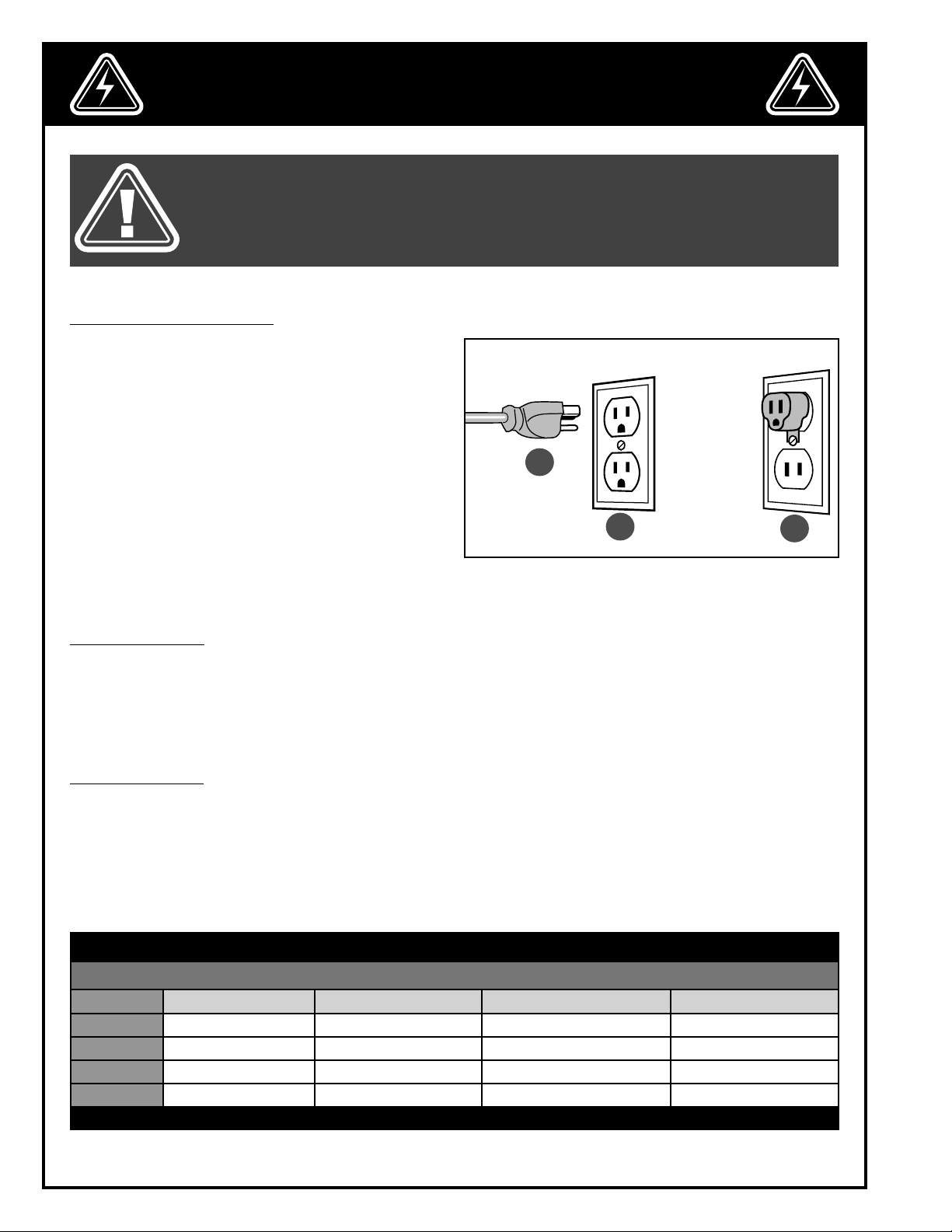
GROUNDING INSTRUCTIONS
In the event of an electrical malfunction or short circuit,
grounding reduces the risk of electric shock. The motor
of this machine is wired for 110V single phase operation and is equipped with a 3-conductor cord and
a 3-prong grounding plug A to fit a grounded type
receptacle B.
Do not remove the 3rd prong (grounding pin) to make
it fit into an old 2-hole wall socket or extension cord. If
an adaptor plug is used C, it must be attached to the
metal screw of the receptacle.
Note: The use of an adaptor plug is illegal in some
areas. Check your local codes. If you have any doubts
or if the supplied plug does not correspond to your
electrical outlet, consult a qualified electrician before
proceeding.
A
B
C
CIRCUIT CAPACITY
Make sure that the wires in your circuit are capable of handling the amperage draw from your machine, as well
as any other machines that could be operating on the same circuit. If you are unsure, consult a qualified electrician. If the circuit breaker trips or the fuse blows regularly, your machine may be operating on a circuit that is
close to its amperage draw capacity. However, if an unusual amperage draw does not exist and a power failure
still occurs, contact a qualified technician or our service department.
EXTENSION CORDS
If you find it necessary to use an extension cord with your machine, use only 3-wire extension cords that have
3-prong grounding plug and a matching 3-pole receptacle that accepts the tool’s plug. Repair or replace a damaged extension cord or plug immediately. Make sure the cord rating is suitable for the amperage listed on the
motor I.D. plate. An undersized cord will cause a drop in line voltage resulting in loss of power and overheating.
The accompanying chart shows the correct size extension cord to be used based on cord length and motor I.D.
plate amp rating. If in doubt, use the next heavier gauge. The smaller the number, the heavier the gauge.
TABLE - MINIMUM GAUGE FOR CORD
EXTENSION CORD LENGTH
AMPERES 50 feet 100 feet 200 feet 300 feet
< 5
6 to 10
10 to 12
12 to 16
*NR = Not Recommended
18 16 16 14
18 16 14 12
16 16 14 12
14 12 *NR *NR
6
Page 7

IDENTIFICATION OF MAIN PARTS AND COMPONENTS
F
B
A
D
C
E
G
H
I
J
L
K
A. MOUNTING BASE
B. COLUMN LOCK LEVER
C. HEIGHT ADJUSTMENT LOCK LEVER
D. ARM ADJUSTMENT HANDLE
E. FEEDER ARM
F. HEIGHT ADJUSTMENT HANDLE
G. ADJUSTMENT ARM LOCK LEVER
H. SUPPORT ELBOW LOCK LEVER
I. MOTOR
J. ON/OFF AND FEED DIRECTION SWITCH
K. FRONT COVER
L. TILT LOCK LEVER
7
Page 8

UNPACKING
Carefully unpack and remove the unit and its components from the box and check for missing or damaged items
as per the list of contents below.
NOTE: PLEASE REPORT ANY DAMAGED OR MISSING ITEMS TO YOUR GENERAL® INTERNATIONAL DISTRIBUTOR IMMEDIATELY.
LIST OF CONTENTS QTY
A. FEEDER ..................................................................................... 1
B. FEEDER ARM ........................................................................... 1
C. MOUNTING BASE ..................................................................... 1
D. HANDLE .................................................................................. 2
E. LOCK WASHER ......................................................................... 4
F. GEAR (24 T) .............................................................................. 1
G. GEAR (26 T) .............................................................................. 1
H. M10 BOLT ................................................................................. 4
I. DRILLING TEMPLATE ................................................................. 1
A
ADDITIONAL REQUIREMENTS FOR SET UP
A. 14 MM WRENCH
B. 5 MM ALLEN KEY
C. DRILL
D. 8.5 MM DRILL BIT
E. 8.5 MM TAPPING TOOL
F. TAPPING TOOL HOLDER
G. SCISSORS
H. WRENCH
B
C
B C
D
E
F
I
H
G
BASIC FUNCTIONS
The General International model 20-200 power feeder is designed to be easy to install and operate on a variety of
woodshop production machines such as table saws, jointers, and shapers.
Once it is properly positioned this power feeder allows the user to feed stock through their production machine
with great stability while maintaining a constant feed speed.
The use of power feeders in the workshop offers several advantages including: greater worker safety by keeping
hands well away from the cutting tool, better work piece finish quality thanks to its steady, consistent feed speed.
With its solid design and easy maintenance the unit is equipped with 3 rubber feed rollers for maximum work piece
grip and a choice of 4 feed speeds to better suit various work piece materials and different types of production
machinery.
8
Page 9

INSTALLATION
This feeder should be installed on a flat, level surface – ideally bolted to the work surface of your production machine A.
If the surface of your production machine is not large enough to accommodate the feeder’s mounting base or if
other technical hindrances (such as cast-iron ribbing) arise, you may be required to adapt your installation.
This may also require you to attach a shop-made auxiliary table to your production machine in order to install the
feeder B.
If this option is necessary check to ensure that your chosen installation location still allows the feeder to be properly positioned for your production machine – see section “Operations – step by step”.
A
4
29
-
308
mm
403 - 201mm
B
AUXILIARY TABLE
(not included)
ASSEMBLY INSTRUCTIONS
BEFORE ASSEMBLING, MAKE SURE THAT THE SWITCH IS IN THE “OFF” POSITION AND THAT THE POWER CORD IS
UNPLUGGED. DO NOT PLUG IN OR TURN ON THE MACHINE UNTIL YOU HAVE COMPLETED THE ASSEMBLY AND
INSTALLATION STEPS DESCRIBED IN THIS SECTION OF THE MANUAL.
INSTALLING THE POWER FEEDER
1. Cut the self-adhesive drilling template according to
the dimensions of the feeder base.
2. Reach under the lip of the table to make sure there
is no cast ribbing in installing area, then stick the
template to the table.
9
Page 10

BEFORE ASSEMBLING, MAKE SURE THAT THE SWITCH IS IN THE “OFF” POSITION AND THAT THE POWER CORD IS
UNPLUGGED. DO NOT PLUG IN OR TURN ON THE MACHINE UNTIL YOU HAVE COMPLETED THE ASSEMBLY AND
INSTALLATION STEPS DESCRIBED IN THIS SECTION OF THE MANUAL.
INSTALLING THE POWER FEEDER (CONTINUED)
3. Drill the table at the locations indicated by the template
using a 8.5 mm or Q (imperial equivalent) drill bit.
Note: Start with a smaller bit to make the drilling easier.
5. Align the base mounting holes with the holes
drilled into the table.
4. Using a tap holder and an 8.5 mm/1.5 tapping
tool, thread the 4 holes.
Note: To avoid threading the holes, you can also secure
the base with nuts (not included).
6. Screw the 4 supplied M10 mounting bolts with the
lock washers into the base.
7. Tighten the 4 bolts using a 14 mm wrench. 8. Insert the column into the base making sure that it
bottoms out in the base.
9. Insert the handle into its support, then secure the
10. Repeat the previous step with the second handle.
handle using a 14 mm wrench.
10
Page 11

INSTALLING THE POWER FEEDER (CONTINUED)
MARCHE
ARRIÈRE
MARCHE
AVANT
0
MARCHE
ARRIÈRE
MARCHE
AVANT
0
11. Loosen the support elbow from the feeder. 12. Remove the support elbow.
13. Slide the support elbow onto the arm. 14. Tighten the elbow with a 14 mm wrench.
A
B
15. Place the feeder under the support elbow and
lower the arm by turning the handlle A until the
elbow touches the feeder cone.
16. Lift the feeder to fit the cone into the support elbow
while someone else turns the lever B to secure the
feeder to the arm.
BASIC ADJUSTMENTS & CONTROLS
TO REDUCE THE RISK OF SHOCK OR FIRE DO NOT OPERATE THE UNIT WITH A DAMAGED POWER CORD OR PLUG.
REPLACE A DAMAGED CORD OR PLUG IMMEDIATELY. TO AVOID UNEXPECTED OR UNINTENTIONAL START-UP, MAKE
SURE THE POWER SWITCH IS IN THE OFF POSITION BEFORE CONNECTING TO A POWER SOURCE.
CONNECTING TO A POWER SOURCE
Once the assembly steps have been completed, plug
the power cord into an appropriate outlet. Refer back
to the section entitled “Electrical Requirements” and
make sure all requirements and grounding instructions
are followed. When operations have been completed
unplug the machine
from the power source.
MARCHE
ARRIÈRE
MARCHE
0
AVANT
SWITCH OFF
TO AVOID UNEXPECTED OR UNINTENTIONAL
START-UP, MAKE SURE THAT THE POWER SWITCH
IS IN THE OFF POSITION BEFORE CONNECTING
TO A POWER SOURCE.
DO NOT WIRE OR CONNECT THE FEEDER
THROUGH OTHER MACHINERY. THE POWER
FEEDER MUST BE ON ITS OWN INDEPENDENT
CIRCUIT.
11
Page 12

MAKE SURE THE MACHINE HAS BEEN TURNED OFF AND UNPLUGGED FROM THE POWER SOURCE BEFORE PERFORM-
MARCHE
ARRIÈRE
MARCHE
AVANT
0
MARCHE
ARRIÈRE
MARCHE
AVANT
0
MARCHE
ARRIÈRE
MARCHE
AVANT
0
REV
FOR
0
REV
FOR
0
MARCHE
ARRIÈRE
MARCHE
AVANT
0
MARCHE
ARRIÈRE
MARCHE
AVANT
0
REV
FOR
0
MARCHE
ARRIÈRE
MARCHE
AVANT
0
ING ANY MAINTENANCE OR ADJUSTMENTS.
ON/OFF POWER SWITCH
The feeder is equipped with a switch/inverter for the
feed direction A.
To turn on the feeder: Turn the switch A to the right B or
to the left C as per the required feeding direction.
To stop the feeder: Turn the switch to the middle position D.
DO NOT WIRE OR CONNECT THE FEEDER
THROUGH OTHER MACHINERY. THE POWER
FEEDER MUST BE ON ITS OWN INDEPENDENT
CIRCUIT.
REV
B D
0
FOR
REV
C
0
A
FOR
REV
0
FOR
CHANGING FEED SPEEDS
1. Remove the lock knob from the front cover, then
remove the front cover.
2. Remove the mounting gear nut E using a 14 mm
wrench.
E
3. Remove the gear. 4. Repeat steps 2 and 3 with the other gear.
12
Page 13

2
0
T
3
0
T
2
4
T
2
6
T
2
4
T
2
6
T
2
4
T
2
6
T
2
4
T
2
6
T
2
4
T
2
6
T
MAKE SURE THE MACHINE HAS BEEN TURNED OFF AND UNPLUGGED FROM THE POWER SOURCE BEFORE PERFORMING ANY MAINTENANCE OR ADJUSTMENTS.
CHANGING THE FEED SPEEDS (CONTINUED)
5. Install the gears as shown below, depending on the
desired feed speed.
Note: The number of teeth (20T, 24T, 26T or 30T) is engraved on the gears.
6. Retighten the two nuts with their washers, then reinstall the front cover.
GEAR INSTALLATION CHART
T
0
2
T
3
0
T
2
6
T
4
2
20 fpm 26 fpm 33 fpm 43 fpm
T
2
6
T
4
2
2
T
3
0
T
0
GUIDELINES FOR SELECTING SPEEDS
CUTTING TOOL SPEED
6000 rpm 8000 rpm 8000 rpm
CUTTING TOOL
WORKPIECE
THICKNESS
6 mm (1/4”)
9 15 23 9 15 23 15 23 23
10 mm (3/8”) 8 12 15 8 15 15 12 15 15
20 mm (3/4”) 5 9 12 6 12 12 8 12 12
25 mm (1”) 3 5 6 5 6 8 6 8 9
POWER FEEDER SPEED (fpm)
13
Page 14

ADJUSTING THE FEEDER HEIGHT AND LENGTH
C
E
A
To adjust the arm length, turn handle A. Lock the handle with lever B.
B
To adjust the arm height, turn handle C. Lock the handle with lever D. Lock the column with the lever E.
OPERATING INSTRUCTIONS
CHECKLIST BEFORE STARTING
VERIFY ALL CHECK POINTS BEFORE STARTING. FAILURE TO COMPLY CAN RESULT IN SERIOUS INJURIES.
1. Make sure you and any assistants are wearing safe appropriate workshop attire. Roll up long sleeves, secure
long hair and remove any jewelry: watches, rings, bracelets or anything that could become caught in the
moving parts, potentially causing serious injury.
2. To reduce the risk of damage to the machine, as well as potential for personal injury, after initial set-up as well
as before each use, make sure that everything is securely installed and that all fasteners and moving parts on
this machine are locked in place before starting the machine.
3. Make sure to have on safety glasses as well as hearing or/and respiratory protection at all times when using the
machine.
4. Use only recommended parts and accessories. The use of parts or accessories NOT recommended by
GENERAL® INTERNATIONAL may result in a risk of injury or damage to the machine.
5. Be sure that adjusting wrenches, tools, drinks and other clutter are removed from the machine and/or the
table surface before operating.
6. Keep the feeder electrical cord far from the cutting tool or the moving parts of your machine.
7. Verify that the feed direction is appropriate for the rotation direction of the cutting tool.
USING THE FEEDER STEP-BY-STEP
KEEP THE FEEDER ELECTRICAL CORD AWAY FROM THE CUTTING TOOL AND ANY MOVING PARTS ON YOUR MACHINE.
F
1. Using a level F, make sure that the feeder is in the
horizontal position. To correct the feeder position,
loosen lever G and level the feeder, then retighten
the lever.
14
G
VERIFY THAT THE FEED DIRECTION IS APPROPRIATE FOR THE ROTATION DIRECTION OF THE CUTTING TOOL.
2. Turn the feeder on.
Page 15

3 mm
USING THE FEEDER STEP-BY-STEP
3. Make a test without turning the production ma-
chine on.
Note: All 3 must be in contact with the workpiece. Note: Lower the rollers 3 mm below the top of the board to
5. If your machine is a shaper, position the feeder directly opposite the cutting tool A. For a table saw the
feeder should be positioned in front of the blade as shown B. With a jointer position the feeder directly
above the cutter head C.
6. Make sure that all the positioning handles are tightened before starting the production machine and the
feeder.
Note: The feeder must be turned few degrees towards the fence in order to stays against the fence throughout the cut.
4. Turn the feeder off and verify that all 3 rollers are in con-
tact with the board as shown below.
maintain a light pressure.
A B
SHAPER TABLE SAW JOINTER
C
15
Page 16

MAINTENANCE
100 cm³
PERIODIC MAINTENANCE
• Inspect/test the ON/OFF switch before each use. Do not operate the feeder with a damaged switch; replace
a damaged switch immediately.
• Keep the feeder and the production machine as well the table clean and free of saw dust, woodchips, pitch
or glue.Vacuum or brush off any loose debris and wipe down the feeder and the table occasionally with a
damp rag.
• Periodically inspect the power cord and plug for damage. To minimize the risk of electric shock or fire, never
operate the sander with a damaged power cord or plug. Replace a damaged power cord or plug at the first
visible signs of damage.
• Rollers must always be kept clean. Dirt on rollers will cause poor unstable workpiece feeding.
REPLACING THE GEAR BOX OIL
Note: The gear box oil should be replaced after the first 30 days or 200 hours of use. After this breaking-in period the oil
should be replaced every 6 months or 1,000 hours of use.
1. Loosen the support elbow using a 14 mm wrench. 2. Remove the feeder from the arm.
Note: Help from an assistant is advisable.
3. Unscrew & remove the oil plug using a wrench. 4. Tilt the feeder down and place a container under
it to drain the gear box oil.
100 CC’s
4. Fill the gear box with 100 CC’s of ISO 150 gear oil. 2. Re-install the oil plug and re-install the feeder.
Note: To avoid damage do not overtighten the plastic plug
16
Page 17

MAKE SURE THE MACHINE HAS BEEN TURNED OFF AND UNPLUGGED FROM THE POWER SOURCE BEFORE PERFORMING ANY MAINTENANCE OR ADJUSTMENTS.
LUBRICATING THE CHAIN AND THE GEARS
1. Loosen the front cover lock knob, then remove the
front cover.
2. Remove old grease and dust deposits by wiping
with a dry rag, then apply dabs of any common
automotive bearing grease to all the moving
GREASING THE ROLLERS
1. Using a grease gun, grease each roller with all-
purpose grease.
components.
2. Wipe down each grease cap to prevent grease
residues being thrown on the rolls and reduce
they grip capacity.
REPLACING THE ROLLERS
The rollers on your power feeder are made of a durable rubber designed to provide a long service life. However
depending on how much the feeder is used, over time it may still be necessary to replace one or even all of the
rollers.
Since the overall efficiency and proper operation of your feeder is directly related to the condition of its rollers,
make a habit of regularly inspecting them for visible signs of wear or damage. Some signs to look for include: deterioration and signs of wear on the rollers surface such as severe discoloration, cracks, tears and scratches, often
caused by foreign objects embedded in the work piece.
Replace any roller as soon as it begins showing visible signs of deterioration. Replacement rollers can be ordered
through your General International retail distributor under part number #20-205
Tip: To avoid potentially costly downtime consider keeping a spare set of rollers on hand and ready for use when needed..
1. Loosen the support elbow lock lever by one full rotation. 2. Pivot the feeder towards you.
17
Page 18

MAKE SURE THE MACHINE HAS BEEN TURNED OFF AND UNPLUGGED FROM THE POWER SOURCE BEFORE PERFORMING ANY MAINTENANCE OR ADJUSTMENTS.
REPLACING THE ROLLERS (CONTINUED)
A
3. Remove the 2 mounting screws using a 5 mm Al-
len key.
4. Install the roller with the reference marks A facing
inward.
Note: Centering/balancing is not necessary the rollers
will balance themselves with use.
Note: Reference marks A are used to identify the inside
face of the roller.
5. Retighten the roller then repeat previous step with
the other rollers.
RECOMMENDED OPTIONAL ACCESSORIES
Here is a sampling of optional accessories available from your local General International dealer that can be
used with this product. For more information about our products, please visit our website at www.general.ca
Item #20-205
RUBBER FEED ROLLER
For model 20-200.
Item #90-805
HEAVY-DUTY ROLLER STAND
18
Item #50-166
FLEXIBLE EXPANDABLE
ROLLER STAND
Page 19

DIAGRAM
POWER FEEDER (20-200)
19
Page 20

PARTS LIST
POWER FEEDER (20-200)
IMPORTANT: When ordering replacement parts, always give the model number, serial number of the
machine and part number. Also a brief description of each item and quantity desired.
PART # REFERENCE # DESCRIPTION SPECIFICATIONS QTY
20200-18A U010051 KNOB M6 -1.0P X 30 L 1
20200-21A-1 U010008 OIL CAP 16 MM 1
20200-21A-2 Q010012 “O” RING 1
20200-21B-1 A500348 GEAR 34 T 1
20200-21B-2 A500349 GEAR 16 T 1
20200-65B-1 C020047 SPROCKET CASE 3
20200-65B-2 N950003 SPRING 30 X 6 3
20200-65B-3 U010054 CASE CAP 3
20200-66B-1 C020334A ROLLER SUPPORT 3
620200-6B-2 A500336 SPROCKET 13T 3
20200-66B-3 N510022 SNAP RING 3
20200-66B-4 S060625 CAP SCREW M6-1.0PX25L 3
20200-67B K330018 CHAIN 18S 3
20200-68B-1 A500331 TUBE 3
20200-68B-2 N510026 SNAP RING 3
20200-69B-1 G320018A SPROCKET SHAFT 1
20200-69B-2 N510015 SNAP RING 2
20200-70B-1 G320017A MAIN SPROCKET SHAFT 1
20200-70B-2 N015925 FLAT WASHER 3/8”X25X10T 1
20200-70B-3 N11010R NUT M10-1.5P 1
20200-71B-1 T315106 GREASE NIPPLE M6-1.0PX1.0 3
20200-71B-2 G320067 SPROCKET SHAFT 3
20200-71B-3 N030008 LOCK WASHER 8.3X1.8T 3
20200-71B-4. N11008R NUT M8-1.25P 3
20200-75B-1 C020051 HOUSING FRAME 1
20200-75B-2 A500306 BUSHING 1
20200-79B-1 G320016 WORM GEAR SHAFT 1
20200-79B-2 N015925 FLAT WASHER 3/8” X 25 X 10T 1
2020079B-3 N11010R NUT M10 -1.5P 1
20200-80B-1 U210007 OIL SEAL 1
20200-80B-2 A500302 BUSHING 1
20200-80B-3 C020322 WORMGEAR COVER 1
20200-80B-4 Q021701 OIL SEAL 17 X 32 X 7T 1
20200-80B-5 S070512 CAP SCREW M5 - 0.8PX12L 4
20200-81B-1 A500327 GEAR 30 T 1
20200-81B-2 A500324 GEAR 20 T 1
20200-82B-1 A500323 GEAR 26 T 1
20200-82B-2 A500326 GEAR 24 T 1
20200-83B Q010060 O RING 1
20200-85M1 85M1 MOTOR W/ SWITCH 1/4HP - 1PH 1
20200-86B U010002 SWITCH BOX KIT 1
20200-87B J120020 SWITCH 1/4 HP 1
20200-96A U010070 HOUSING COVER 1
20200-112B-1 A500303 SPROCKET 12T X 3/8” 1
20200-112B-2 A500307 DOUBLE-SPROCKET 12 T 3
20200-112B-3 A500308 BUSHING 1
20200-112B-4 K330030 CHAIN 30 S 1
20200-112B-5 K330022 CHAIN 22 S 1
20200-RO081 C020302 ROLLER (ITEM #20-205) 80 X 30 X 1PC 3
20
Page 21

DIAGRAM
MODEL: US01 LIGHT-
DUTY UNIVERSAL STAND
POWER FEEDER ARM (20-200)
IMPORTANT: When ordering replacement parts, always give the model number, serial number of the
machine and part number. Also a brief description of each item and quantity desired.
PART # REFERENCE # DESCRIPTION SPECIFICATIONS QTY
20200-85H-1N U010106 SUPPORT HANDLE 2
20200-85H-2 N810430 PIN 2
20200-87A U010011 HANDLE M10-P1.5 X 70L 2
20200-90B-1 A200326 COLUMN BASE 1
20200-90B-2 N015816 FLAT WASHER 5/16”X16 1
20200-90B-3 G020012 LOCK LEVER 1
20200-90B-4 N11008R NUT 1
20200-90B-5 S601050 SCREW 4
20200-90B-6. N030010 LOCK WASHER 4
20200-91B G020013 ELEVATION COLUMN 40 X 465L 1
20200-92B G020014 EXTENSION ARM 40 X 465L 1
20200-93B-1 A200327 ELEVATING BRACKET 1
20200-93B-2 N015816 FLAT WASHER 5/16” X 16 2
20200-93B-3 G020012 LOCK LEVER 2
20200-93B-4 N11008R NUT 4
20200-93B-5 G000006 SET SCREW 2
20200-93B-6 N030008 LOCK WASHER 2
20200-94B G320092 ELEVATION SCREW 1
20200-95B G320091 EXTENSION SCREW 1
20200-96B-1 C020323A COLUMN CAP 2
20200-96B-2. G000005 SET SCREW 3
20200-98B-1 A200328 SUPPORT ELBOW 1
20200-98B-2 N11216R NUT 1
20200-98B-3 G020011 LEVER 1
20200-98B-4 N015925 FLAT WASHER 3/8” X 25 X 10T 1
20200-98B-5 S601050 HEX SCREW 1
20200-99B-1 A200321 SWIVEL CONE 1
20200-99B-2 N11216R NUT 1
20200-99B-3 G020011 LEVER 1
21
Page 22

8360 Champ-d’Eau, Montreal (Quebec) Canada H1P 1Y3
Tel.: (514) 326-1161
Fax: (514) 326-5565 - Parts & Service / (514) 326-5555 - Order Desk
orderdesk@general.ca
www.general.ca
Follow us:
 Loading...